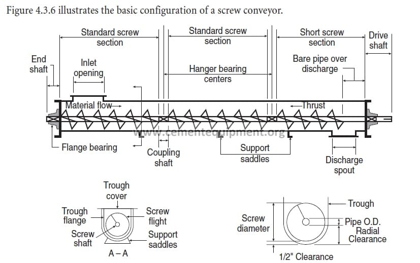

A hot screw-conveyor gearbox usually points to excessive mechanical load, lubricant condition, bearing distress, misalignment or poor heat rejection. Start with the load evidence: compare motor current, throughput and gearbox temperature with a healthy baseline; verify oil level and grade, inspect breather and seals, check coupling alignment and conveyor resistance, then correlate vibration/noise with bearing and gear condition. Do not cool the housing externally or change oil viscosity blindly before finding the heat source.
Find why the screw-conveyor reducer heats, trips, smells hot or degrades oil before gears, bearings, seals or the driven screw are damaged.
Use motor current, reducer temperature trend, oil condition/level, vibration, noise, coupling alignment, screw resistance and start-stop history.
Separate overload, lubrication, internal bearing/gear damage, alignment and ambient/cooling causes before replacing the reducer.
Fast diagnostic order
- Confirm whether heat follows load: compare gearbox temperature, motor current and throughput against the normal conveyor duty.
- Check lubrication before teardown: verify oil level, specified grade, foaming, contamination, leakage and breather condition.
- Inspect the driven machine: look for plugging, rubbing, damaged flights, blocked discharge and seized hanger or end bearings.
- Separate alignment from internal damage: check coupling/base condition, vibration, noise and local hot spots.
- Verify after correction: trend temperature, current and vibration through unloaded and representative loaded operation.
Preserve the operating evidence before shutdown
Record: gearbox housing temperature at repeatable locations; motor current; conveyor throughput; frequency of loaded starts; any plugging history; reducer input/output speed; oil level; visible leakage; breather condition; vibration/noise; coupling condition; ambient temperature; and whether the temperature rise follows high load, long runtime or recent maintenance.
If the gearbox has several temperature points, map them. A local hot bearing area is different from the whole housing heating uniformly.
1. Compare mechanical load with the normal conveyor duty
Reducer heat often increases because the driven conveyor is asking for more torque than normal. Check motor current and throughput together. Inspect for overfilled troughs, compacted material, wet cement, foreign objects, blocked discharge, damaged flights, shaft rubbing or seized hanger/end bearings. A gearbox that heats only when current rises is telling you to investigate the driven machine before blaming the reducer.
2. Verify lubricant level, grade and service condition
Check oil level using the reducer manufacturer’s method and the machine in the correct stopped or operating state. Too little oil can starve gears and bearings; too much can create churning losses, aeration and heat. Confirm the installed lubricant matches the reducer specification for viscosity and additive type. Inspect for darkening, burnt odor, foaming, water or metallic debris. If maintenance recently changed the oil, verify that the correct product and fill quantity were used.
3. Check the breather, seals and housing ventilation
A blocked breather can pressurize the housing as oil heats, pushing lubricant past seals and drawing contamination when the gearbox cools. Clean or replace the breather according to the OEM procedure. Inspect shaft seals for leakage paths and dust ingress. Also check whether cement buildup, guards or insulation are trapping heat around the housing. Restore the designed airflow around the reducer rather than adding improvised cooling that hides the source.
4. Inspect coupling and shaft alignment
Angular or offset misalignment at the motor-reducer or reducer-screw connection can increase bearing load and heat. Look for coupling element wear, abnormal dust, fretting, loose hubs and movement at the base. Verify hold-down bolts and support structure. If alignment measurements are taken, compare them with the coupling and reducer supplier’s target, including any required operating offset. Do not use flexible couplings as a permanent correction for poor alignment.
5. Use vibration and noise to separate bearing from gear-mesh distress
A bearing problem can create broadband or characteristic-frequency vibration and local temperature rise, while gear distress may produce mesh-related vibration, knocking, whine or metallic debris. Compare input and output bearing locations. Inspect magnetic drain plugs or filters if fitted. Large chips, rapid debris increase or a new mechanical knock justify a controlled inspection rather than continued operation based only on temperature.
6. Review loaded starts, reversals and shock events
Frequent starts with a full screw, plugging events or sudden reversals can impose high transient torque. Check the operating sequence and whether upstream equipment continues feeding after the screw slows or trips. Review overload-relay or VFD event data where available. Correcting the process sequence may reduce heating more effectively than changing reducer size without understanding the duty.
7. Inspect the reducer during a planned shutdown
If external evidence points inside the reducer, inspect oil, gear tooth contact, bearing condition, backlash/endplay and internal fasteners according to the OEM manual. Look for pitting, scuffing, discoloration, spalling and unusual wear distribution. Preserve oil and debris samples when useful. The objective is to link the internal condition to the external trend, not just to confirm that the unit is ‘hot.’
Gearbox overheating diagnostic matrix
| Observed pattern | Likely direction | Priority check |
|---|---|---|
| Heat rises with motor current and throughput | Overload / conveyor resistance | Plugging, trough fill, bearings, rubbing, discharge condition |
| Hot after oil change | Wrong level/grade or aeration | Lubricant specification, fill quantity, foaming |
| Local hot spot plus vibration | Bearing or alignment issue | Bearing location, coupling alignment, base condition |
| Heat plus metallic debris/noise | Internal gear/bearing distress | Oil/debris analysis and controlled internal inspection |
| Heat high but load and vibration normal | Cooling/ambient/ventilation issue | Housing airflow, buildup, breather, ambient condition |
Common mistakes
- Replacing the gearbox while the conveyor remains overloaded or plugged.
- Adding thicker oil without confirming the OEM viscosity requirement.
- Ignoring overfill, which can increase churning and temperature.
- Cooling the housing externally and masking progressive internal damage.
- Changing coupling alignment without checking the base and driven shaft condition.
Return-to-service verification
After corrective work, run the conveyor unloaded and then through representative production conditions according to site procedure. Acceptance means gearbox temperature stabilizes in the normal plant/OEM trend, motor current matches the healthy duty, vibration/noise do not deteriorate, there is no renewed oil leakage or debris, and the driven screw operates without rubbing or abnormal resistance. Record the new temperature/current baseline for future trending.
Frequently asked troubleshooting questions
What usually causes a screw-conveyor gearbox to overheat?
Common directions include excessive conveyor load, wrong oil level or grade, bearing/gear distress, coupling misalignment, poor ventilation and repeated loaded starts.
Can too much gearbox oil cause overheating?
Yes. Overfilling can increase churning and aeration losses. Confirm the correct oil level using the reducer manufacturer’s method before adding lubricant.
How do you tell a gearbox fault from a conveyor-load problem?
Compare gearbox temperature with motor current, throughput and screw resistance. If heat rises with load/current, inspect plugging, rubbing and conveyor bearings before condemning the reducer.
Related Infinity technical guides
References
Use the installed reducer and screw-conveyor OEM manuals for lubricant grade, fill level, alignment, bearing clearances, temperature limits and inspection criteria. Compare all trends with the plant’s known-good operating baseline.