Contents
Rotary Kiln Maintenance
Attention : click here to Download Most Important books + manuals + excel sheets + formulas + everything you should know in Cement industry , CLICKHERE NOW
Rotary Kiln Alignment
The continuity of operation of a kiln requires strict maintenance control. The rotary kiln is among the largest type of moving machines made and is subjected to extreme temperatures, power failures, atmospheric conditions, varying loads, and other operating conditions which affect its wear and alignment. It should be erected under the supervision of an experienced erecting engineer.
Even though great care has been taken in the design and the construction of the concrete piers, in some cases settling or tipping of the foundation can occur,
throwing the carrying mechanisms, bases,
and rollers out of alignment. If this
condition is not corrected, it will lead to continual trouble with the kiln shell and the riding rings and rollers. It is advisable when making the original installation of the kiln to establish bench marks away from the kiln foundation. The kiln alignment should then be checked from the bench marks within six months after initial installation, and annually thereafter.
Carrying Roller Adjustment of the Kiln
Heavy localized loadings leading to adverse wear can be encountered if the rollers and riding rings do not make contact across the full width of face, or if the rollers are cut excessively.
The carrying mechanisms are equipped with adjusting screws for roller and bearing adjustment. Rollers can be adjusted correctly by means of these screws.
The thrust rollers are designed to carry the full downhill thrust of the kiln, with the riding ring and roller faces lined up for full bearing across the width. Carrying rollers should be set parallel to the riding ring and roller surfaces. Operators should be discouraged from adjusting only the most easily accessible rollers, which would be on the discharge end mechanisms. A record of all roller adjustments should be kept as an aid to maintaining proper alignment.
Warping
When a kiln with a hot charge is stopped for any reason, such as a power failure, it is imperative to keep the kiln rotating with the auxiliary drive. Failure to do so may result in a warped or distorted kiln shell. It is difcult to return a warped shell to its original condition, and operating a kiln with a bowed or warped condition will place an excessive load on various mechanism piers. This is particularly troublesome in multiple support kilns.
Sometimes a warped kiln can be returned to somewhat its original alignment by carefully re-heating the kiln on the side opposite from the warp to draw it back in line. Even at best, though, constant attention must then be given to the carrying mechanisms to provide an alignment which will not cause additional damage or excessive wear.
Sometimes the only way in which to correct a warped or bowed condition or misaligned shell is to cut out a portion of the shell, realign the ridng rings and carrying rollers, and weld the shell section back in. This might result in a slightly disjointed shell, but the items of major importance, namely the riding rings and rollers, are then realigned.
A warped shell, of course, can lead to continual trouble by decreasing brick life.
Rotary Kiln Drive
Some kilns are installed without auxiliary drives. This is false economy, since the small additional cost of the auxiliary drive in the initial installation provides good insurance against much more serious difFculties.
The kiln drive is located close to the thrust ring to maintain the main gear and driving pinion in proper relation regardless of expansion and contraction of the kiln.
The main gear, usually a spur gear, is made in halves with full machined teeth to permit reversing of the gear to obtain a double life. This gear is bolted to a gear ange which is welded to the kiln shell. The driving pinion is mounted on a jackshaft which is coupled to the low speed shaft of an enclosed gear reducer. The gear reducer and jackshaft assembly is xed to the foundation on the same slope as the kiln, and is provided with adjusting bolts and lugs on the base plate to provide for alignment of the drive. The driving motor is usually connected to the high speed shaft of the gear reducer through a multiple V-belt drive. The motor is also mounted on the same slope as the kiln. Ball bearing motors should always be used, since oil will run out of the bearings on a sleeve bearing motor.
The main gear and pinion should be maintained in proper mesh. Improper meshing of the teeth results in a jerky or vibrating motion of the kiln. Too small a clearance will cause bottoming of the main gear on the base of the pinion teeth. Proper adjustment of the carrying rollers to compensate for the wear on the tires and rollers should prevent this condition.
If a minimum adverse clearance is allowed to continue with a resulting scoring of gear teeth and peening of pinion teeth, it will be necessary to reverse the gear and pinion before such action is normally necessary and then reset the drive accordingly.
Misalignment of the kiln or pinion may also cause the teeth to wear to a taper, resulting in inferior gear action and shorter life.
Rotary Kiln Vibration
Large, slow moving equipment such as rotary kilns will have a low natural frequency of vibration which in some cases could coincide with a kiln speed. Were this to occur, there would be a pronounced vibration of the kiln on the supporting rollers, and knocking and pounding in the main gear and the gear reducer. If such a condition were allowed to continue, the foundations and the kiln could be severely damaged.
The design of the kiln installation insures a natural frequency of vibration well out of the range of recommended operating speeds. Consequently, the kiln speed should never be changed without rst investigating the effect which the increased speed might have on the vibrational characteristics of the kiln.
HOW TO CHECK KILN ALIGNMENT
Horizontal Rotary Kiln Alignment
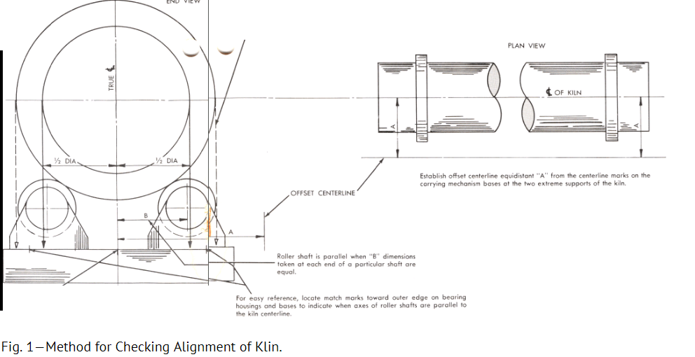
Conrm the original centerline of carrying mechanism bases. To do this, establish an offset centerline, preferably with piano wire, along the side of the kiln from the rst to the last support where visibility is unobstructed, as shown in Figure 1. This offset centerline should be equidistant from the centerline marks on the carrying mechanism bases at the two extreme supports of the kiln. By tramming from this offset centerline, determine if the centerline marks on the carrying mechanism bases are all in line.
If the intermediate piers are not in line, determine whether they or the end piers have settled before proceeding with the alignment work. Some changes may be required in order to bring either the bases or piers into line, depending on whether or not the settling has reached its nal stages. If no further settling is anticipated, or in cases where no settling has taken place, the offset centerline should be permanently located by setting lead or brass markers into the piers or oor. The true centerline should be clearly marked on each carrying mechanism base by tramming from the offset centerline.
Check the setting of the kiln shell in relation to the true centerline of the bases. This can be done by stringing a cord with a plumb bob attached to each end over the top of the shell as near the riding rings as possible. In cases where there are irregularities in the shell, the cord should be strung over the wearing faces of the riding rings. This cord must be long enough to permit the plumb bobs to hang free beneath the kiln, as shown in Figure 1. The midpoint of the distance between these plumb bobs is the center of the kiln shell at that position. Mark this point on the bases and proceed with the same operation at the next support. Rotate the shell 90 degrees and repeat the markings at each support. The mean of the four marks at each quarter point through a complete revolution will then indicate the path from support to support of the true centerline of the kiln shell.
This check will indicate one of two conditions:
The centerline of the shell coincides with the true centerline of the bases established ABOVE
The centerline of the shell is:
Diagonal to the true centerline of the bases.
Parallel, but offset, to the true centerline of the bases.
Bowed in relation to the true centerline of the bases.
If condition (2) applies, the carrying rollers must be adjusted so that the true centerline of the kiln shell is made to coincide with the true centerline of the bases. The carrying rollers must be kept parallel to the centerline of the kiln shell and carrying mechanism bases, as shown in Figure 1. In making these adjustments care must be taken to maintain the proper clearance at the feed end and discharge end air seals and at the main drive gear and pinion.
Vertical Rotary Kiln Alignment Procedure
This check should be made when the kiln is shut down and at a time when the shell is not distorted by either radiant heat from adjacent kilns or the sun. Tape the circumference of each riding ring so the distance from the outside diameter of the riding ring to the center of the kiln can be determined for each ring. Set up a transit or level on top of the kiln over the feed end riding ring. Adjust transit so the line of sight is parallel to centerline of the kiln at the feed end and discharge end riding rings. Check the distance from the riding ring to line of sight for each intermediate ring, repeating this check at quarter points around the circumference. Knowing the radius of each riding ring, the average misalignment at each mechanism can now be determined. Correct this misalignment by making the necessary adjustments to the carrying rollers. The slope of the kiln can be checked with the transit at this time.
With the kiln now in correct vertical alignment, a simple gauge can be constructed to check vertical alignment at each mechanism without having to shut down the kiln and go through the elaborate measurements outlined above. This consists of a gauge pin or tram just long enough to reach from the mark of the true centerline on the carrying mechanism frame to kiln shell. A pin should be made for each mechanism frame. Gauging the distance between the frames and the shell will indicate the extent of wear on the rollers and riding rings. The carrying rollers can then be moved in to return the kiln to its original elevation.
Since the shell may not be perfectly round at the planes where the measurements are taken, reference points should be established on the shell so that the vertical distances between the mechanism bases and the shell will always be gauged at the same points on the circumference of the shell. Reference points can be made by welding four ¾-in. nuts to the shell in each plane where measurements are to be taken. These nuts should be spaced 90 degrees apart. A bolt can then be turned into each nut to a point where the head of the bolt will just touch the gauge pin. The bolt is then welded to the nut. Four of these bolts are used at each mechanism to provide an average reading.
Rotary Kiln Alignment Method
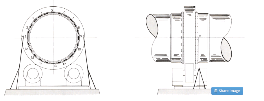
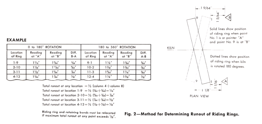
The FLoating type riding rings should not wobble as the kiln rotates, since it is impossible to obtain full contact between the carrying rollers and riding ring under such conditions. Figure 2 shows a method for determining the amount of runout in a ring.
Two pointers are constructed of angle iron and placed as shown. By using two pointers the effect of any kiln “FLoat” is eliminated. These pointers should be mounted on the kiln pier away from the carrying mechanism and should extend to the centerline of the kiln. The edge of each pointer should be approximately one inch from the machined outer edge of the riding ring.
The riding ring must be FIxed against one of the retaining bands by driving small wedges between the riding ring and the other retaining band at several points around the circumference of the ring.
Measurements are taken from reference marks on the pointers to the machined sides of the riding ring. A set of readings taken at 16 equally spaced points around the circumference of the ring will indicate the location and magnitude of maximum runout. If the runout at any location exceeds it must be corrected by relocating the retaining bands and riding rings.
The table in Figure 2 shows how these readings are tabulated and interpreted.
Carrying and Thrust Roller Alignment
When rollers are set parallel to the centerline of the kiln, the roller shafts should bear against the downhill bearing caps. This can be checked by tapping the bearing caps with a hammer. The loaded caps will emit a solid sound.
Check each downhill bearing cap to make certain there is no excessive downhill thrust on any cap. This is done by cutting the roller to just relieve the pressure of the roller shaft against the cap. Note how much the adjusting screw was turned. Then return the roller to a setting which will just produce a light roller shaft force against the downhill bearing cap. After all the rollers are adjusted
the kiln will bear against the lower thrust roller. Care must be taken to avoid excessive thrust roller loading.
Sometimes, when starting up a new kiln with the carrying rollers set parallel to the axis of the kiln, the carrying rollers and riding rings will not make 100% contact throughout the complete revolution of the kiln. In such cases it is better to let the rolling surfaces wear in to obtain full contact rather than to adjust the rollers to obtain full contact immediately.
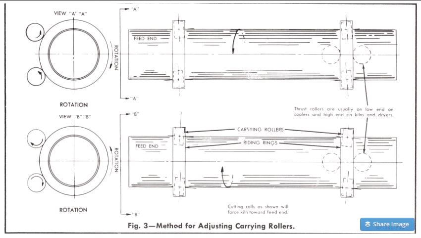
The thrust mechanisms on modern kilns are designed to carry the full thrust of the kiln. On many older kilns, however, it is necessary to carry much of the thrust by adjusting the carrying rollers, since the thrust mechanisms were not designed to take the full thrust load. To “oat” the shell of such a kiln, thus reducing or even eliminating completely the thrust on the downhill thrust roller, the carrying rollers are set at an angle as shown in Figure 3. The illustrations exaggerate the amount of adjustment to show the principle involved more clearly. Any such adjustments must be performed carefully with each roller to avoid excessive pressure with resultant wear from developing on any one roller.
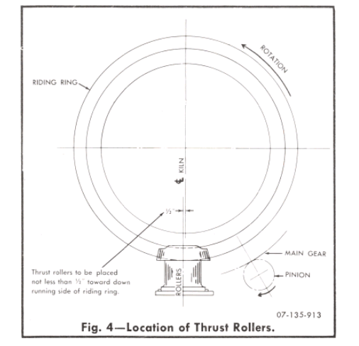
The thrust roller should be installed on the down-running side of the kiln centerline, as shown in Figure 4. This will prevent any lifting effect on the thrust roller.
Inspect a Rotary Kiln’s Gear and Pinion Alignment
The main gear is equipped with adjusting screws to facilitate centering of the gear on the shell. This gear must run true. Several points around the circumference of the gear should be checked with a feeler gauge for uniform contact across the full face of the teeth. Flange bolts should be inspected periodically to be sure they are tight at all times. A tight t can be achieved by pulling each bolt up tightly, then heating the bolt to about 350 F and advancing the nut an additional 20 degrees.
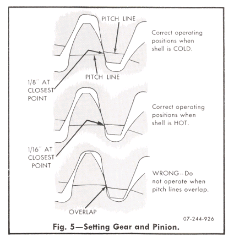
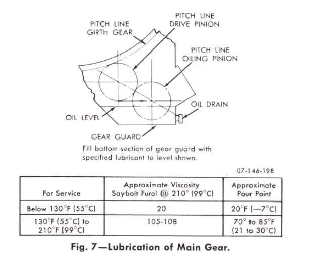
The pinion and gear must mesh properly, as shown in Figure 5. Pitch lines are scribed on both sides of the gear and pinion at the factory. The pinion should be set so the pitch lines on the gear and pinion are 1/16 in. apart when the shell is cold. When the shell is hot the pitch lines should be from 0 to 1/16 in. apart. In no case should the pitch lines overlap, since this would cause excessive wear and overloading of the pinionshaft and bearings.
The mesh of the gear and pinion should be checked at regular intervals. Any wear or adjustment on the carrying rollers will change the mesh. If the pinion is meshing too deeply, the kiln should be raised to its original position by moving the carrying rollers in toward the centerline of the kiln. It should not be necessary to back the drive out to obtain the correct mesh. While the drive is equipped with adjusting screws, these are mainly for use in the initial alignment of the drive. Sometimes it becomes necessary to back the drive away from the kiln to relieve a serious condition which, if permitted to continue, would result in damage to the gear and pinion. This must be considered only a temporary expedient, and the drive should be returned to its correct location immediately upon returning the shell to its true centerline in the recommended manner.
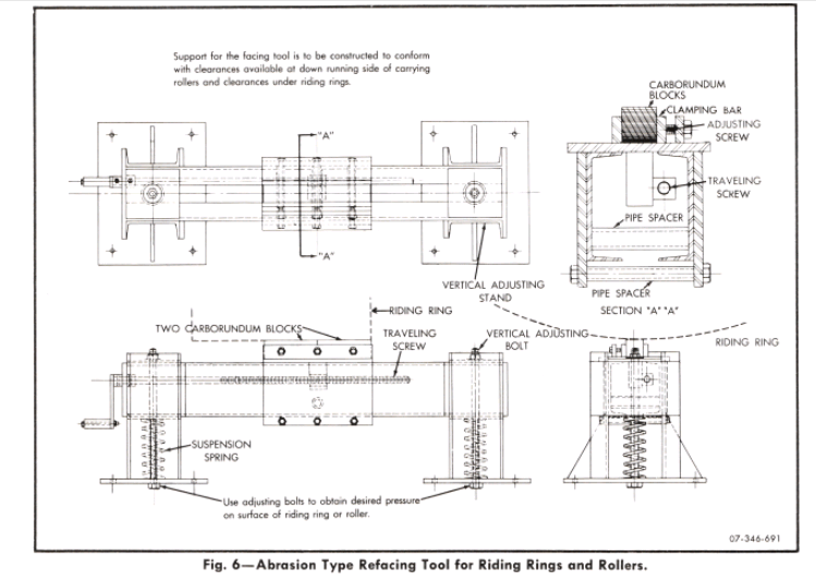
Refacing Riding Ring and Rollers of a Lime Kiln
Sometimes it becomes necessary to reface riding rings or rollers. A grinding rig, shown in Figure 6, can be constructed on the job and used to reface the riding rings while the kiln is in operation. The coil springs and adjusting bolts serve as a stop so that the high spots on the ring will be ground off rst. In operating this refacing tool, a reference mark should be established on the side of the riding ring being ground, and the adjusting screw on the tool turned one revolution per revolution of the kiln to assure even grinding across the face of the ring. Any circumferential ridges on the ring must be ground off FIrst.
If it is not feasible to operate the tool throughout a full 24-hour period, it is a simple matter to lower the grinding table on the adjusting bolts, thereby removing the carborundum blocks from contact with the riding ring. This tool can also be adapted for refacing the carrying roller by tipping the rig up on its side and setting it against the face of the roller. This can be more easily accomplished on the outer side of the carrying mechanism due to space limitations, especially at the thrust mechanism. These rollers can also be refaced by using a lathe and cutting tool arrangement, or it may be more expedient and economical to put the kiln on cribbing and reface the rollers in the machine shop. In either case, whether the ring and roller are to “wear in” over a period of time or whether they are to be refaced, it is essential to watch the following:
That the unit is not moved off its centerline.
That the slope is not changed.
That the proper mesh between the pinion and main gear is not destroyed.
ROTARY KILN LUBRICATION
Rotary Kiln Drive
Use high grade lubricant with specications shown in Figure 7. After a new kiln has been in service for one month, drain oil and clean reservoir. Rell with new oil. Thereafter change oil every six months.
The motor, gear reducer and exible couplings should be lubricated in accordance with instruction sheets furnished by the manufacturer.
Carrying and Thrust Mechanisms of the Kiln
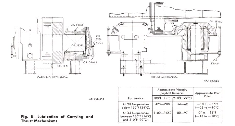
Use high grade lubricant with specications shown in Figure 8. The oil level should be checked at frequent intervals and maintained at the proper level. When starting a new kiln the level should be checked daily. The oil should be changed after the rst month of operation and at six-month intervals thereafter.
Riding Rings and Rollers
Floating type riding rings should be lubricated between riding rings and ller bars with a graphited grease. Initially, apply lubricant to the inner surface of the riding ring at all spaces between ller bars. Subsequent applications of lubricant need be made only at four evenly spaced points around the circumference of the ring. The lubricant can be most easily applied with a hand gun with extended nozzle.
Floating Type Air Seal
Lubricate contact faces of seal with a mixture of graphite and oil. A 3/8-in. pipe tapped hole is provided in the outer diameter of the seal for introduction of lubricant.
Why Kiln floating is required? Is Its is only mechanical requirement or and impact on kiln through put?