Contents
Raw milling and blending
TO DOWNLOAD THIS POST AND ALL OTHER IMPORTANT BOOKS IN CEMENT INDUSTRY KINDLY CLICK HERE
Raw milling must produce sufficient feeq to sustain the required kiln production, meeting targets for fineness, chemica lcomposition and moisture. With multiple tasks.to accomplish, process flow and control become quite complex .Operators need a dear understanding of both basic principles and interrelationships to get the best results.
Raw milling
Usually each raw component is stored and fed separately to the mill, from which product is sampled and chemically analysed to determine adjustment of feed proportions by addition .of corrective components tG maintain the target clinker composition.Older mills may have silos for raw material storage, but the occurrence of feed problems with moist materialhas led to a preference for hoppers.
Mill produet is monitored either by continuous online analysis or by laboratory analysis of hourly grab or composite samples. Computer control effects feed corrections and maintc; ins the desired optimum average compositi0n.
Powder samples can be acquired more or less continuously by devices exposed to downward material flow, while rock samples require grinding and blending.Sample.extraction, preparation and transport to a central laboratory mean that corrective steps are delayed. Modern online techniques, outlined in Section 2.2, allow rapid correction and greatly reduced variation of mill product chemistry. Any continuous analysis system requires reliable and uninterrupted material transport and feeding, which can be a serious challenge.
Operation of the various types of mill and separators is described in more detail under cement milling (Section 6.2). Grinding aids are rarety employed because savings via decreased power consumption are·not cost effe’ctive. However,Whitehead and Kaya (2018) point out that in some circumstances the amounts of coarse quartz and calcite can be reduced, and improve kiln output rate and fuel consumption due to enhanced combinability ofthe kiln feed.
The main difference to cement mill operation is the need to dry raw·feed and assure transport of stightly moist materialwithin a mill. Also, many raw materials are softer than clinker, and operations must avoid coarse residues in kiln feed that are difficult to combine in the kiln and would result in high clinkerfree-lime, and/or excessive fuel consumption.Optimum kiln feed fineness must be determined empirically and should be as coarse as the kiln will tolerate.

Materials are dried in the raw mill whenever possible, because:A narrow size distribution is optimal because fines tend tQ increase d!Jst loss by entrainment in exhaust gas. The use of larger residues may be acceptable when they arise from natural rock.s but requires checking by laboratory combinability tests. Larke et al(201312) describe a plant trialusing an extremely-coarse raw mix, following laboratory tests in which calcareous raw materialwas ground more coarsely. A major gain in mill output was achieved, with no detrimental effect upon cement quality.
- Less equipment is
- Waste heat from preheater exhaust is us.ed
- S02 from preheater exhaust is scrubbed.
Mill production is determined by the grinding power available and feed grindability, but for high moisture feed, the system drying capacity may bethe limitingfactor.Typically,thetarget moisturelevel ex-mill is belo.w one per cent to assure good flowability of raw mealfor ease of handling.
Hammer/impact mills can be used for pregrinding(predrying purposes, aheaa of a·conventional mill, often with a type of flash drier.
Raw mill sweep with preheater exhaust is called compound operation. The raw grinding and clinker burning operations become interdependent and constant kiln operation is required to ensure control of mill temperature and pressure. When the kiln is down, the mill must also stop .unless auxiliary heat is provided. When the mill is down, preheater exhaust must be cooled to maintain acceptable gas flow and temperature for. dedusting. Gas conditioning by a water spray tower is usual, put if water is scarce, ambient air tempering can be used. Air-to-air heat exchangers were not common ly used for dust-laden exhaust gases due to the tendency to cause build-up and plugging, but examples are becoming more common.
A new raw mill das·sifier is now invariably of the ‘high-efficiency’, rotating cage-type: the rotational speed controls product fineness at constant gas flow.
Raw milling can consume 10 30kWh/t; depending upon the materials and equipment, and developments aim to reduce this figure. Around 90 per cent of new raw mills are vertical roller mills, though many ball mills (commonplace until the 1970s) are still in use.
Roll presses are also used; part·icularly in upgrading existing ball mill circuits either to increase production or reduce power consumption. A press can accept material up to around 75mm in size and act as either a pregrinderfor a ball mill (perhaps with a disagglomerator to strip fines from the pressed cake), or as an integral unit with its own gas circuit for drying. Such presses (with a limited number of suppliers) have only made a limited market penetration, a key element of success being improved separators, such as the KHD Humboldt WedagV-Separator ,introduced in 1994, although other designs tend to be preferred for new installations.
Ball mills equipped with a .drying compartment and adequately swept with hot gas (1.5-3m/s above the ball charge),can handle feed with above 10 per cent moisture and a maximum size of around 25mm,preferably much less.With a tandem hammer mill, the maximum feed moisture content may be around 12 per cent if the mill exit diameter is large enough to keep the gas velocity low. Centre discharge mills (‘double rotators’) and fully air-swept mills (5-6m/s) can also dry up to 14 per cent moisture. One of the limitations of an air-swept ball mill is dependence upon the gas stream for material transport. The recirculating load is limited to about 75-150 per cent. Efficiency can be gained by using higher recirculating loads and conveying the material mechanically can achieve this. Typical bucket elevator installations are designed with a recirculating load capacity of up to 500 per cent, with the added advantage that the grinding efficiency within the mill tends to be greater due to improved control of material fiow. Bucket elevator mills are not designed for gas sweeping and so are limited to raw materials with below about 4-5 per cent moisture.
For feed moisture of up to six per cent,drying is effected by partof the kiln exhaust at temperatures of up to 300′ C. Obviously a high drying requirement m y be inconsistent with maximising kiln thermal efficiency – generally five- and six-stage preheaters are only employed where subsequent drying requirements are minimal. Alternatively, but more expensive ly, dedicated hot-gas generators can be used for drying in the mill or hotter gases from a lower cyclone .stage or the cooler exhaust may be used. Drying Is also ald.ed by heat dissipati.on from mill drive power which equates to approximately lt moistur-e per 1000kWh. Higher moisture burdens require larger mill bodies, increasing the cost.
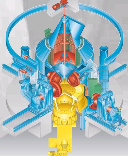
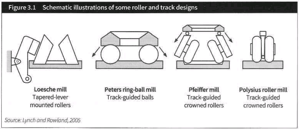
Vertical roller mills have some 33 per cent lower sp.ecific power consumption than ball mills and have come to dominate the scene since their introduction during the 1970s. These mills (see Figure 6.3.) comprise two to six rollers which are hydraulically pressed on to a horizontalrotating grinding table. Feed material is directed to the centre of the table and thrown outwards by rotation under the rollers and into a rising air current at the periphery that is dir’€cted by means of louvre ring ports. The air passes through an integral rotary classifier and fines pass out with the air current while coarse material falls back to the table. Depending on different suppliers the rollers are, frusta-conical, cylindrical or spherical in Shope; and in some cases may have.an axis of rotation inclined at s.ome 15 degrees to the horizontal, as indicated schematically in Figure 3.1.
Material dries in air suspension·between table and classifier. The circulating load is typically 800 per cent. Roller mills are prone to vibration due to an unstable grinding bed,often caused by fine, dry mill feed. Spr-aying water directly to tht> hP.d isthe usual solution, which also conditions the gas.Roller mills can dry and grind coarse moist feed (max “’18 per cent moisture with an auxiliary furnace) of up to 125mm in size, preferably 80-lOOmm. They are compact, with the classifier built intothe mill body.
Operationally, roller mills are quite sensitive to changes in parameters. Abrasive raw materials such as sand can cause quite rapid wear of grinding surfaces. Material is retained on the table using a dam ring at its circumference. As the table wears, the depth of material on the tab(e increases and mill power consumption increases. This is·not normally a problem unless the mill motor is approaching full load, in which case the dam ring height must be reduced to compensate for table wear and avoid restricting feed rate. Detection of tramp metal in mill feed and its removal are important precautions.
Specific power consumpti9n depends upon materia.! hardness and millefficiency. For ball mills the range is from approximately lOkWh/t (mill drive only) for soft, chalky limestone to 25kWh/t for hard materials. Compared to ball mills, energy savings for VRM circuits can be around 30 per cent. FLSmidth claims the world’s largestVRM installation for raw materials, rated at 8700kW and capable of producing 750-lOOOtpd .at around 26kWh/t.
Air emerging from a mill carries 50-500g/m3 of fine material,requiring a velocicy of some l5-20m/s to ensure entrainment, demanding the use of powerful fans. Raw meal is collected by a fabric filter or other dust collector -with its funct ion being as much to collect product as to clean gas.
PoittiP.r (?018) reviews the latest evolution ofthe Horomill, suggesting that the correct configuration for raw milling is closed circuit with a third generation Tsvn• classifier and perhaps a flash dryer in the gas circuit.
Raw mills are monitored by:
– production rate (tph}
–operating hours (h)
–involuntary downtime (h)
– mill motor specific power·consumption (kWh/t)
– mill circuit power consumption (kWh/t)
– maximum feed size (mm)
– product fineness (o/o finer than 300m and 125m)
– feed moisture (o/o)
–product moisture(%)
– pressure drop (mm WG)
–limestone (o/o}; day/sha le (o/o); additives(%)
– inlet and outletgas temperatures (·C)
– furnace fuel consumption (kJ/t oldry product)
– noise level(dB).
Additional operating parameters required periodica lly include:
– circulating load (o/o)
–steel L!Sage (g/t)
–chemical analysis of +90 m fraction.
Analysis of the coarse (+901Jm) fraction may be lime-rich or, more likely,silica-rich, relative to the total sample but should show constant bias.
Downtime analysis can usefully highlight reasons for lack of availability and identify target areas for improvement. For example, significant mill blockages would indicate an issue related to drying capacity. Factors external to the mill are highlighted, such as feeder starvation due to handling and drying problems inthe crushing department.
Blending
This is another critical process stage. Deficiencies will impair product quality, reduce kiln output, increase both fuel consumption, refractory wear and, potentially, grinding costs with lower throughput for similar 28-day strengths. For optimum results a kiln feed with the correct chemistry and particle size distribution is essential – with, above all, a minimum of variability. A major cause of customer dissatisfaction and complaint is not the absolute concrete strength levelachieved with the cement but its variability.
Because customers require similar properties for cements from different sources, and also to optimise clinker production, there has been a pragmatic trend to converge on a ‘standard’clinker chemistry ina narrower range than often repeated from historical descriptions (Moir, 2003):
- LSF: 95-97%
- silica ratio (SR):4-2.6
- alumina ratio (AR):5-1.8.
Most plants have to use corrective materials such as sand and iron oxide to achieve this range, and the blending system has to produce a raw feed that uniformly yields such a clinker.
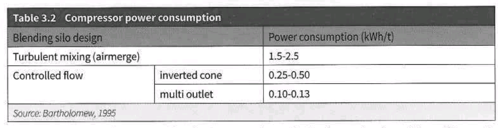
The two major types involve turbulence (in which the material is tumbled about by injection of high volume air through air-pads on the floor) and controlled flow (CF – where sequenced light aeration of segments of air-pads causes layers of material in the silo to blend by differential rates of descent). CF silos may have multiple discharge chutes, or an inverted cone over a centre discharge within which the meal isfluidised. Approximate compressor power consumption is shown inTable 3.2.
Turbulent mixers can be operated batch-wise or continuously. The former involves either a filling cycle corrected progressively to average thetarget mixor asequence offilling, mixing,sampling and analysing, correcting, remixing, andthen feeding to the kiln. Continuous blending involves simultaneous feeding of the silo, overflow to a second silo and final discharge to kiln feed.
Modern equipment generally uses continuous CF silos, each having capacity of more than 24-hours’ kiln feed and yielding a blending ratio (or ‘blending factor’) of 4-8, or around 2-3 for older silos. Note that a given silo will show a lower blending efficiency if the feed isconsistent. The retention time of raw meal ina blending silo affects blending ratio and may be easily monitored by the addition of zinc oxide or fluorescein to silo feed (see Section 84.7). Apart from power savings, the effective capacity of a CF silo issome 20 per cent greater due to the higher bulk density of meal which is not heavily aerated. The design of modern blending silos isdescribed by Halbleib (2003).
Blending silos should be monitored by:
- blending ratio (s(..,jsr-M,)
- compressor power {kWh/t of throughput).
Blending silos are prone to internal build-up of dead material, particularly if raw meal is wet or aeration defective. Periodic (one to two years) internal inspections and maintenance are necessary. As raw meal may solidify if left inactive {during a kiln shutdown for example),blending silos may require emptying or recirculating when not inuse.
To ensure good blending action, itis preferable that materialchemistry varies both above and below its target set-point on several occasions during the silo residence time.
With the availability of real-time, online analysis of mill feed or product, chemistry can be maintained within narrow limits and modern plant designs frequently dispense with kiln feed blending or cut down the size of prehomogenising stockpiles. However, such procedures do not work well when faced with certain origins and frequencies of variability in a major raw mix component, or with corrective components that are either difficult to extract from storage and accurately dose, or that are difficult to combine within the kiln {Harrisson, 2013).Rather than investing inequipment to correct the chemistry of the feed on itsway to the kiln,an improved quarry management system to deliver a more consistent supply of limestone provides a superior solution.
Kiln feed
Both raw meal chemistry and feed rate to the kiln must be consistent to avoid kiln instability and minimise fuel consumption. Short-term feed fluctuations {eg hunting of feeder control) should be monitored, as well as average feed rate.
Suspension preheaters lose a fraction of kilnfeed entrained inexhaust gas.As this fine fraction isusually of a typical composition, kiln feed analysis must bebiased to yield the desired clinker composition. The dust loss, some 5–U per cent of kiln feed, is not usually collected until after it has passed through a raw mill or dryer, so that dust catch is not the same quantity or composition as preheater dust loss. Even if the dust collector catch is returned directly to the kiln, it must still be compensated. Likewise, care must be exercised to minimise chemical disturbance due to dust return, particularly when the raw mill is down and the dust collector catch changes from mill discharge instead of kiln discharge. The least negative option is feeding to the blending silo or to a separate storage tank for subsequent controlled return.
If the kiln exhaust passes directly and continuously to dust collection,then the dust may be returned directly to the preheater- sometimes, iflow inquantity, re-entrainmentcan beminimised byinsufflation at the hood injection at the upper end of the kiln.Either way, the return rate should be controlled.
Kiln feed is monitored by chemical analysis on four- or eight-hourly grab samples – not cumulative samples – to determine standard deviation results (see Section 2.6).Analysis is conventional for major oxides with variation monitored statistically In terms of C S or LSF.
Kilns, particularly the larger ones, are intolerant of variations in feed chemistry. The general rules for chemistry controlat the raw milling stage are similar, no matter how many mix components are available, and are basically simple:
- If the chemistry is not at the desired level: change it!
- If a parameter is below the desired level: increase itto above that {Known as ‘crossing the target line’-as seen on a controlchart -and failure to do this usually results in ‘off-target’batches of raw meal.)
- When makinga change,pay due regard to previous results and weighfeeder (This is important when batch blending, where the concept of keeping a weighted average of all material chemistries entering a silo is often advantageous.)
- Where possible, use continuous samplers: spot samples can often be misleading and cause erroneous
- Residues are very important and their testing and control demands as much care as bulk chemistry checks.
Variations in fuel ash should not be overlooked and ash should be considered as part of the raw mix argillaceous component. Ifthequantity fed into the kilnvaries,thechemical variability of theclinker will also vary. Plants with high fuel consumption and/or high fuelash contents should minimise variations by blending the fuel(s) .
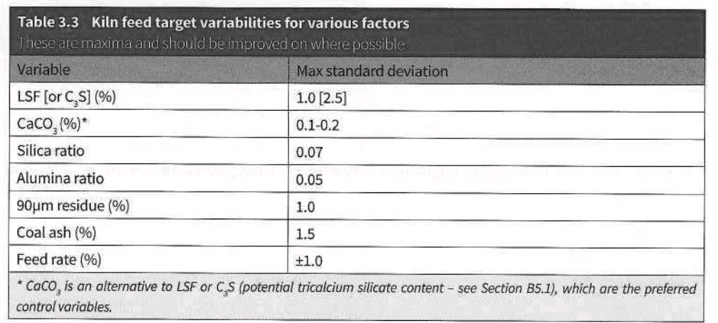
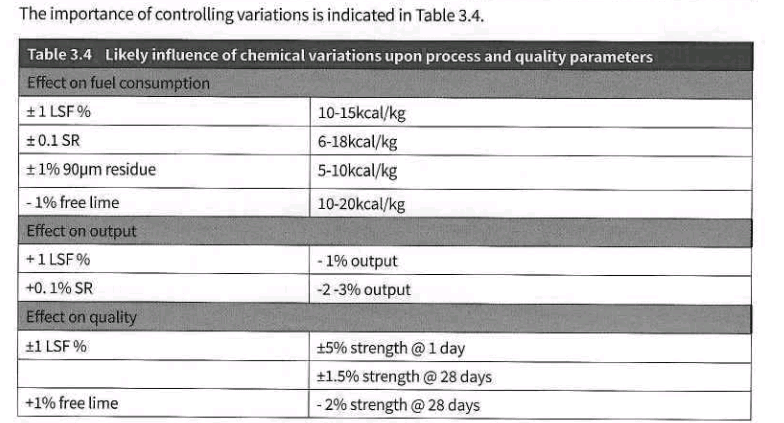
It should be remembered that standard deviation is not a perfect measure of variation as, simply i!pplied, it does not distinguish between a steady trend and constant fluctuation. Kiln operators need to respect maximum tolerable limits upon variability- see Table 3.3.
Kiln feed Is normally conveyed by bucket elevator to the top of the preheater. Pneumatic conveying wastes energy, and feed de-aera tion Is desirable before injection as the entraining air adds to the kiln ID fan load and may reduce capacity.
Although about l.SSt raw materials are required to produce 1t of clinker,kiln feed-to-clinker ratio is typically 1.65-1.75 as weighed, due to the loss of dust with exhaust gas, later collected and returned. The ratio should be periodically reconciled with clinker and cement inventories and with measured dust loss in the preheater exhaust.
- Kiln feed = clinker+ Lot+ bypass dust+ down comer dust- coal ash
where both bypass dust and down comer dust are converted to a loss-free basis