Contents
Raw Material Homogenization and Storage IN
CEMENT INDUSTRY
[wpecpp name=”package + Updates forever” price=”250″ align=”center”]

UNIT FIVE
Raw Material Homogenization and Storage
5.0 Raw Material Homogenization and Storage
As the daily practice demonstrates, chemical fluctuations in the raw mix have a considerable influence on
kiln operation e.g. coating and ring formation as well as encrustation and clogging problems. Therefore the
degree of homogeneity directly influences the life time of the refractory lining. Homogenization of the raw
materials and the raw mix is thus of utmost importance. Homogenizing Efficiency normally expressed by:
e = sα/sβ
Where;
sα: Standard deviation of the unhomogenized raw material
sβ: Standard deviation of the homogenized raw material
Since the homogenizing efficiency is a function of sα and sβ, the factor (e) can be low although the
preblending bed or the homogenizing silo works satisfactorily, i.e. the fluctuations sβ of the homogenized
material are within the tolerable limit. This is the case if the original fluctuations sα are small. If (contrarily)
sα is very large, the fluctuation sβ can be unacceptably high although the homogenizing efficiency factor is
large and within the specifications.
Due to this ambiguity of the factor (e), it is better to specify the desired maximum value for the standard
deviation sβ of the homogenized material.
5.1 Preblending of Raw Material
In recent years, the improvement of quality with greater raw material utilization and optimum applications
of processing plants is being striven after more and more in the sector of raw material beneficiation.
Greater and greater fluctuation in properties of raw materials such as ores, limestone and, in particular,
run-of-mine coal, removed from deposits suitable for mining today, therefore demands that blending
equipment ensures a high-quality end product.
From a materials-handling aspect it is more favourable to disconnect mining operations from processing
plants and to optimize each separately, so that undesired fluctuations in the flow of material and standstills
in handling are prevented.
Stockpile homogenization systems equalize variations of chemical and physical properties of raw materials
and convert low quality raw materials into a uniform mixture of higher quality as required for cement
production, coal fired power plants or for example steel production.
5.1.1 Definitions & Theoretical Considerations
In a stockpile, bulk solids are stacked to and subsequently reclaimed from a storage facility. Generally a
conventional pile can perform the following functions:
1) Buffering/ Distributing: is the function of providing sufficient reserve of raw material to guarantee a
continuous operation of the processing plant under all normal circumstances. The stockpile acts as a buffer
between continuous and discontinuous operation of a mine or quarry, a processing or power plant or acts
as a distributing system of a bulk terminal.
2) Composing/ Blending: is the function of the integration of number of raw materials with different
chemical and/or physical characteristics in such proportions that a completed pile represents the requisite
composition.
3) Homogenizing: is the function of systematic transformation of the input flow of the pile into the output
flow, so that the fluctuations of a property in the flow are evened out.
In nature raw materials occur in varying grades, even within the most uniform deposit. When regular
increments of the raw material stream are sampled and analysed the degree of variation can be measured.
Mostly this variation approximates a normal distribution.
The aim in the homogenizing/ blending operation is to narrow down the standard deviation of this normal
distribution.
Ideally, the raw material stockpile is laid by a belt stacker in as many thin layers of identical volume as
possible. As a result of this large number of layers, varying material properties in superposed layers are
offset by the cutting process of machines in operation. The law of continuity tells us that each cross-section
of the stockpile contains the same amount of material and this fact is the essential prerequisite for a good
homogenization effect. The number of layers is determined by the cross section of the pile, the handling
capacity and travelling speed of the stacking machine.
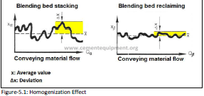
The figure (fig-5.1) shows in principal the fluctuation of the incoming raw material quality around a certain
average value X (with line across top). The deviation from this value is Δx. The second diagram shows the
decreased fluctuation after the material is leaving a stockpile homogenization system.
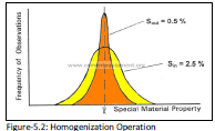
The figure (fig-5.2) shows clearly the effect of the homogenizing operation with a standard deviation of the
incoming material of 2.5 % and after reclaiming an improved deviation of only 0.5 %. The practical
application of this method, however, is limited by the missing information on the stockpile volume, the
correlation between the stockpile layers, the different layer thickness, reclaiming method, errors during
sampling and analysis. Therefore, an empirical factor (k) is to be considered which is obtained by
comparison of theoretical values with those received from practical sampling of various homogenization
systems under comparable conditions.
Homogenization Effect (e) = k. √n
Where;
n: Stockpile layers (the result shows us, that the homogenization effect is a function of the stockpile layers
n).
k: empirical factor (normally varies between 0.5 and 0.7)
5.2 Classification of Typical Homogenization/ Bending Plants
5.2.1 Types of Preblending Bed
5.2.1.1 Longitudinal Preblending Bed
The longitudinal preblending bed represents the most common and simplest type of preblending bed. This
type always corresponds to batch wise blending since one pile has to be formed while the other is
reclaimed. Different stacking/ reclaiming methods are designed and used widely in raw material
homogenization and storage.
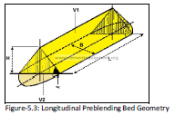
The total volume of longitudinal pile (fig-5.3) can be calculated simply as the following:
Pile Height (H)
H = 0.5 x B x tanα
Volume of Prismic Part (V1):
V1 = [(B x H x L)/ 2] = [(B2/4) x tanα x L] ——————————————- eq.1
Volume of Cone end Part (V2):
V2 = 0.5 x [(B2 x H)/12] x π = 0.5 x [(B3 x tan α)/24] x π ————————- eq.2
From eq.1 & 2:
Total Volume (Vtotal) = V1 + 2V2 = [(B2/4) x tanα x L] + [((B3 x tanα)/24] x π]
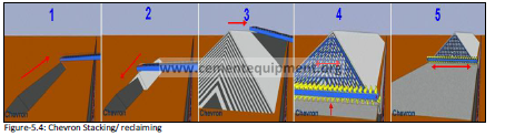
5.2.1.1-a Chevron Stacking/ Reclaiming
The stacker travels at almost constant speed back and forth along the entire length of the stockpile. The
boom is raised according to the growth in height of the stockpile. The material is afterwards reclaimed in
slices transversal to the pile by means of a front acting reclaimer. This is the common stacking method for a
longitudinal pile with front reclaiming (fig-5.4).
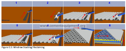
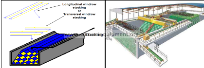
5.2.1.1-b Windrow Stacking/ Reclaiming
![]()
![]()
Several longitudinal layers are stacked parallel over the whole width of the pile in such a way that they
form a triangular pile face after completing the full height (fig-5.5). In other words the stacker not only
makes longitudinal but also transversal movements so that a pattern of parallel, longitudinal rows arises.
Reclaiming is always done by a front acting machine. Note that due to the higher investment cost as
compared to Chevron, the Windrow stacking is only applied if a large segregation in the end cones is
expected (e.g. max. grain size > 100 mm).
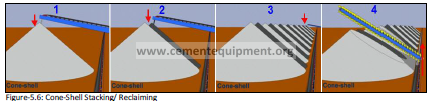
5.2.1.1-c Conical Shell Stacking/ Reclaiming
![]()
![]()
The stacker moves stepwise in longitudinal direction. The next step is only executed after completing the
conical shell up to the full pile height (fig-5.6). Reclaiming is normally done laterally by a side-reclaimer.
Note that the Conical shell stacking method should not be applied in conjunction with front reclaiming
since only few material layers are blended so that the achievable homogenizing efficiency is rather poor.
This method is used for preblending beds with side reclaiming in case of sticky materials and if the
homogenizing efficiency is not important.
5.2.1.1-d Stacking and Reclaiming in Homogenizing Pit
The stacking method in the homogenizing pit could be both, either Windrow stacking in longitudinal or
transversal layers (fig-5.7). Reclaiming is performed by a bucket chain excavator lifting and discharging the
material on to a bridge mounted transversal extracting belt. Note that the homogenizing pit is applied for
small preblending capacities or for sticky materials requiring a good homogenizing efficiency. Due to the
high investment cost, the homogenizing pit is not used for ‘normal cases’ where the longitudinal Chevron
bed can be applied.
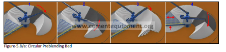
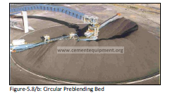
5.2.1.2 Circular Preblending Bed
![]()
![]()
The Circular Blending system is designed for continuous Chevron stacking in one ring shaped pile (fig-5.8).
Stacking is effected by a fan shaped sprinkling action in an arc determined by the type of material being
processed to ensure appropriate homogenisation. Reclaiming at the other end of the pile is effected by a
bridge reclaimer working parallel to a radius line. For cement production the pile between the bridge
scraper and the stacking zone is a buffer. The material enters the store on a belt conveyor and is
discharged into a centrally positioned inlet hopper on the stacker jib.
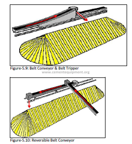
5.2.2 Stacking Machines
The stacking machines dealt with here after allow the stacking according to the Chevron, Windrow and
Conical Shell pattern. For stockpiling the material there are (in principle) two different types of machine.
Throw-off carriages (tripper) fed by a belt conveyor installed under the ridge of the roof of the storage
building can be used only for stockpiles under cover. Laterally travelling boom stackers can be used for
covered as well as for open-air stockpiles. The figures (fig-5.9 & fig-5.10) schematically illustrate a throwoff
carriage with a fixed depositing chute for building up bed-blending stockpiles on the Chevron principle.
If the throw-off carriage is equipped with a cross-traversable or a slewing throw-off belt, it can also be used
for Windrow stacking. For this purpose the stackers are designed with slewing gear or with a telescopic
boom.
The solution with a throw-off carriage operating along the ridge of the roof has the disadvantages that the
material undergoes segregation as a result of the great height from which it falls, that the material in the
pile becomes compacted, and that dust is thrown up. These disadvantages are obviated by stackers
equipped with booms that can be lowered. Segregation can be reduced by variable reversing points of the
stacker set according to the slope of the pile end.
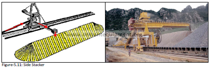
Because of the counterweight needed to balance the boom stacker, a machine of this type is rather wide
and therefore requires a fairly large amount of clear working space within the storage building (fig-5.11).
The maximum number of layers to be deposited will depend on the stacking performance and the
maximum travel speed of the machine. The highest travel speeds are around 25-30 m/min. with a pile
width of 30 m and a stacking capacity of 1000 t/h having 400 to 500 layers. In present-day practice the
combination of Chevron stacking with a front-acting reclaimer has found widespread acceptance as a
favourable system, since this method of stacking can be achieved with the least elaborate machinery.
In general the same machineries as introduced on the longitudinal preblending bed do also apply for the
circular piles. The tripper carriage or side stacker of the longitudinal pile is replaced by a slewing stacker
boom turning around the preblending bed center column.
5.2.3 Reclaiming Machines
5.2.3.1 Front Acting Reclaimers
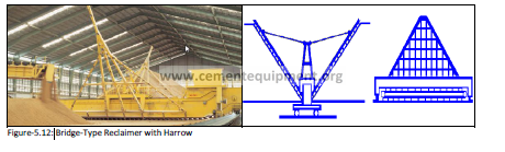
This type of reclaimer equipped with an extracting scraper chain (fig-5.12) is the mostly applied reclaiming
machine. The highest attainable performance for these bride-type reclaiming machines is around 500 m3
/h. Bridge spans in the region of 50 m are already in use.
Advantages of this type of reclaimer are:
a) The homogenizing effect is good because slices of the whole cross-section of the pile are reclaimed.
b) The output rate is constant and easy to control.
c) Only a small amount of clear working space is needed for the machine inside the storage shed.
d) The working direction of the machine can be changed quite simply.
Disadvantages of this type of reclaimer are:
a) There is an upper limit to the output attainable.
b) For feeding the exit belt conveyor the machine requires (on the discharge side) a feeding table or
delivery chute, to enable the discharge to the exit belt.
c) As the machine moves continuously into the pile and the scraper chain is filled progressively towards the
discharge point; the bridge has a tendency to move at the back and more quickly that at the front end.
Provision must be taken that this oblique movement can be corrected.
Figure-5.12:
5.2.3.1-a Dislodging Device
All front-acting reclaimers are equipped with a material handling system which can pick up the material
only from the toe of the stockpile. A dislodging device, for bringing the material down from the slope,
sweeps across the end face of the pile. The material contained in a thin slice undergoes blending while it
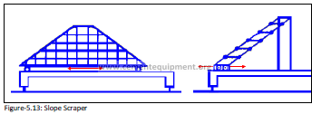
rolls and slides down. Machines equipped with harrows or rakes, rope-operated scrapers and scraper
chains for dislodging the material are available (fig-5.13). Harrows are normally triangular in shape with
renewable teeth and capable of being tilted to the natural angle of repose of the material. Dislodging the
material is achieved by the oscillating to-and-fro movement of the device. Scraper chains are more
particularly suited for dislodging difficult and heavy materials from stockpile slopes. In performing their toand-
fro motion they sweep the whole end face and force the material by positive action to the tow of the
slope. The rope-operated scraper comprises two ropes which pass around pulleys at the tip of the pile
attached to a slide which performs a shuttle motion along the bridge. In this way the ropes pass to and fro
across the whole face of the pile in the manner of windscreen-wipers. For dealing with heavy material the
ropes are interconnected by pivoted cross-beams studded with teeth. In this way the loosening and
dislodging effect can be substantially increased and the wear on the ropes reduced.
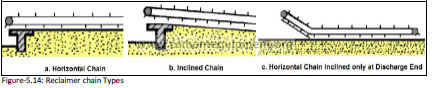
Generally; the scraper chain extracts the material to the side of the pile where it is discharged onto the exit
belt. Different types of chain arrangements can be distinguished (horizontal, inclined or inclined) only at
the discharge end on the exit belt (fig-5.14). A discharge table is for the horizontal as well as for the
inclined chain an indispensable prerequisite. The horizontal chain inclined at the discharge end therefore
needs only a delivery chute which is less expensive compared with the concrete transfer.
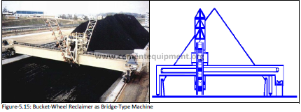
5.2.3.1-b Bridge-Mounted Bucket-wheel reclaimers
A bridge-mounted bucket-wheel reclaimer takes the material from the tow of the slope and discharges it to
a transverse belt mounted on the same bridge. The dislodging device is attached to the support of the
bucket-wheel and moves to and fro with it (fig-5.15).
The advantages of this type of reclaimers are:
1) Good homogenizing effect: The variations that occur because the machine does not sweep the whole
cross-sectional area of the pile all the time in the to-and-fro motion of the bucket-wheel are of short
duration and can without difficulty be evened out in the subsequent raw material processing stages.
2) The output performance is virtually unlimited: For high reclaiming rates it is possible to mount two or
more bucket-wheels on one and the same bridge.
3) Sideways discharge of the material onto the exit belt conveyor is done by a belt installed in the bridge:
This is an energy-saving arrangement compared with the bridge-type scraping reclaimer and makes it
possible to construct a low retaining wall as the lateral boundary to the toe of the stockpile. Thus there is
no risk of overfilling, and the amount of space required is kept down to the minimum.
4) The bridge is moved stepwise while the bucket-wheel is in its extreme position. It is therefore no
pronounced danger for oblique movement to the bridge.
Disadvantages of this type of reclaimers are:
1) The rate of discharge of the reclaimed material does not remain constant as the bucket-wheel moves
transversely. This drawback is compensated by switching to three different speeds for the traversing of the
bucket-wheel.
2) The clear working space required is greater than for the bridge-type scraping reclaimer.
3) On reversal of the working direction the buckets have to be reversed too.
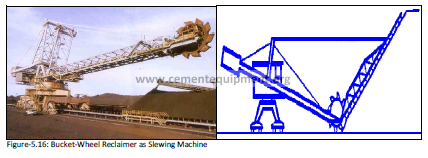
5.2.3.1-c Bucket-Wheel Reclaimers with Slewing Boom
Machines of this type operate in the same way as the machines described above, except that the
reclaiming face is not flat but curved (fig-5.16). The advantages of this type are the same as in bridgemounted
bucket-wheel reclaimer but the most important one is that since the rails on which the machine
is mounted are within the stockpile itself, there is an additional saving of space.
The disadvantages are the same as those associated with the bridge-mounted bucket-wheel reclaimers.
Turning the machine inside a building requires much space, which is an additional disadvantage of this type
of reclaimer.
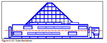
5.2.3.1-d Tube Reclaimers
With this type of machine the material dislodged by the to-and-fro motion of a harrow is picked up by
scoops mounted on a rotating tube or drum and is deposited onto a belt conveyor running inside the tube
(fig-5.17). The blending effect that they can attain is excellent, as their reclaiming action comprises the
whole cross-section of the stockpile. However, they are sophisticated and expensive machines which can
be economically employed only for very high reclaiming rates (upwards of 2000 t/h).
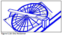
5.2.3.1-e Disc Reclaimer
This type of reclaiming machine is an entirely new concept of a reclaimer. It only has in common with the
other reclaimers that it acts also on the front of the pile (fig-5.18).
In disc reclaimer; the rotably disc structure supported by a bridge spanning the width off the bed agitates,
transports and discharges the material continuously over the rim of the pile onto the exit belt. The only
parts of the machine that are in contact with the material to be reclaimed are the harrow teeth connected
to the spokes, the bottom edge of the rim, the inside of the rim and the carriers along the rim. If the
material has reached the rim of the pile it slides down the pile side over the reclaiming wall onto the
collecting conveyor. The disc inclination can be adjusted on the slope of the pile face. The machine can
reclaim in two opposite directions by simply tilting the disc from one position through the horizontal to the
other position. If necessary the disc could discharge at either side by selecting the rotation direction.
5.2.3.2 Side Reclaimers
Side reclaimers acting from the side of the preblending bed are equipped with a boom mounted scraper
chain that can be lowered. They work either on the front of the preblending pile or on the side.
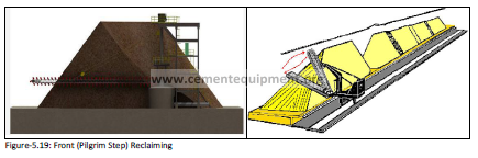
5.2.3.2-a Side Reclaimers Working on the Front of the Pile
Reclaiming of the material from the pile is done by lowering and lifting the scraper chain on the pile face
simultaneous forwards and backwards movement of the reclaimer carriage (fig-5.19). This method of
reclaiming has severe drawbacks and should not be installed anymore due to:
1) Complicated sequence control of boom and carriage and thus high maintenance requirement.
2) Irregular material discharge flow requiring large belt capacities (fluctuations reached up to 50 %).
In circular preblending bed; front acting reclaimers moving the material to the center discharge by means
of a bridge mounted scraper chain are normally used. The center discharge consists of a funnel from where
a tunnel underneath the pile withdraws the material and conveys it to the surface.
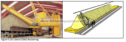
3.4.2.2-b Side Reclaimers Working on the Side of the Pile
The lowering boom reclaims the material from the side of the pile while the carriage travels the whole
length of the pile (fig-5.20). This working method is only applied in conjunction with Conical shell stacking.
Their respective advantages and disadvantages can be summarized as follows:
Advantages:
1) Several material components stored on the same preblending bed can be served by a common
reclaiming machine (e.g. additives stored on the same preblending bed).
2) Suited for fairly sticky materials.
3) Low investment costs.
Disadvantages:
1) A diminished homogenizing efficiency is obtained since not all layers are blended simultaneously
(Conical shell stacking).
2) Suited only for homogeneous raw materials (additives) with fluctuations
s <= 2 % CaCO3.
3) Preferred only if the available preblending bed concept demands a simple automatic material storage
with no or less homogenizing requirements.
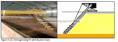
5.2.3.2-c Reclaiming Machines for Sticky Materials
In the cement industry it is often necessary to deal with materials that tend to stick. In such cases
difficulties are liable to arise with some types of machine described in the foregoing, because in certain
circumstances the material refuses to be easily dislodged and come tumbling down to the tow of the pile.
The side-acting scraper can still be used for such materials. The scraper blades are normally provided with
ripper teeth in that case, and devices for cleaning the blades when dealing with extremely sticky material
have been developed. Alternatively, an easily modifiable version of the slewing-boom bucket-wheel
reclaimer can be employed for the purpose (fig-5.21). Here the raking device for dislodging the material
from the slope is omitted, and the bucket wheel is raised to reclaim directly from the stockpile.
Unfortunately in both cases the blending effect achieved by such machines is diminished. A third
possibility, without loss of blending effect, is provided by the homogenizing pit with bucket chain
reclaimer. Because of the high cost of construction the pit to receive the material, these blending
installations are expensive. Under favourable conditions it is possible to construct the pit by blasting it out
of solid rock and thus saving money. In comparison with stockpiles of triangular cross-section the space
required by such tanks is substantially less. Under cramped conditions in a specific case it will therefore be
the most economical one even in a case where the material to be dealt with is not particularly sticky. The
application of this type of installation is also indicated for small storage capacities where the space for a
Chevron bed becomes too large.
5.2.4 Material Segregation in the Preblending Bed
The mathematical models to calculate the homogenizing efficiency, the capacity and the number of layers
of the preblending bed are based on the assumption that the material layers are stacked in an ideal
manner one upon the other. The longitudinal piles as well as the circular piles stacked according to the
Chevron method have at both extremes of the stockpile two semi-conical ends with unideal stratification
and material segregation. When the reclaimer takes its first slices out of the end cone it picks up only
coarse material. There are various ways and means of improving these adverse end-cone conditions, can
be summarized in:
1) By adopting a high length /width ratio for the pile; the volume of the end cones is reduced.
2) One end cone at the ‘far end’ of the pile can always be left standing or be only partly reclaimed. Of
course, this does not alter the situation at the ‘near end’ cone; besides, there is a loss of efficiency
stockpile volume.
3) The material in the end cones can be recirculated to the second stockpile. This procedure is time and
energy-consuming and should therefore be applied only in special cases.
4) The reversal points of the stacking machine can be staggered in relation to the height attained by the
stockpile during the course of building it up. In this way the segregation at the ‘near end’ cone can be
reduced.
5) These end cone problems are obviated if a circular stockpile with continuous stacking is adopted for the
blending bed.
5.2.5 Preblending Bed Applications
The selection of the appropriate preblending bed is dependent on many factors, the most important are:
Plant layout, material properties (stickiness, grain size, etc.), environmental influences (weather
conditions), feeding capacity, storage capacity, raw mix proportioning, and the storage capacity expansion.
5.2.5.1 Longitudinal Preblending Bed
The longitudinal preblending bed is best suited if a more component or integrated preblending bed is
chosen, since a defined chemical value within one pile can be obtained. However, material segregation in
the end cones has an unfavourable influence on the homogenizing efficiency of the preblending bed. The
roofed preblending bed is a simple construction. Instead of a side stacker with a movable undercarriage
the stacker can then be installed under the ridge of the roof. But especially the unroofed preblending bed
is considered favourable, since it is the cheapest solution.
5.2.5.1-a Longitudinal Preblending with Side Reclaimer
The side reclaimer is a relative simple machine which is low in investment and low in maintenance cost. It
is well suited also for very sticky materials. The side reclaimer represents a cheap solution if several
materials are stored on the same preblending bed in line, since the different piles can be served by one
common side reclaimer. The achievable homogenizing efficiency is rather poor, since not all layers are
reclaimed simultaneously.
5.2.5.1-b Longitudinal Preblending Bed with Front Acting Bridge Reclaimer
The bridge reclaimers should favourably be applied if a good homogenizing efficiency is required and for
the materials which are not extremely sticky.
5.2.5.2 Circular Preblending Bed
Normally circular preblending beds are slightly cheaper because of less civil costs for roofing. However, this
statement depends much on the local condition. If the preblending bed is not covered this argument is
inapplicable. The respective advantages and disadvantages can be summarized as follows:
Advantages:
1) No material segregation at the end cones if the next pile is formed adjacent to the foregoing or by
continuous stacking.
2) Good space utilization; this argument becomes only true for adjacent piles or continuous stacking.
3) The continuous stacking method allows the adaptation of the homogenizing volume in comparison with
the storage volume.
Disadvantages:
1) When having an integrated preblending bed stacking is rather preferred in two or more segments
(batchwise) than continuous. However stacking in segments has the drawback that before starting a new
segment first a material free segment plus the space reservement for the reclaimer has to be free.
2) The central discharge arrangement can become problematic if the material is sticky and difficult to
handle.
3) Machine parts as central slewing boom stacker bearing and lifting device are sensitive units exposed to
excessive wear and therefore need special attendance.
4) The extraction tunnel is exposed to ‘water break in’.
5) Expansion of the existing preblending bed is not possible.
5.2.5.3 Homogenizing Pit
The usual applied preblending bed type for sticky materials is the homogenizing pit. This type of
preblending bed represents an expensive solution since excessive civil work is implied. As the material is
stacked in longitudinal or transversal layers according to the windrow method a good homogenizing
efficiency can be expected.
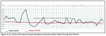
5.3 Silo Concepts for Raw Meal Beneficiation
In Cement Industry raw meal blending or homogenization is always done in silos. It is the last beneficiation
step in the line of the raw mix preparation processes installed with the aim to reduce the residual
(relatively short-term, high frequent) compositional variations observed for the raw meal produced in the
raw mill (fig-5.21). The raw meal reclaimed from such blending or homogenization silos will then be fed to
the kilns without further beneficiation. Therefore it is a challenge for all cement plant operators to achieve
for the raw meal ex blending or homogenizing silo a quality that meets narrow uniformity specifications
regarding chemical composition and physical characteristics. This as a prerequisite for achieving steady
process conditions for the kiln.
The silo concepts used in raw meal beneficiation can be classified according to the kind of the working
principle applied into the following categories:
1) Air-fluidized systems
2) Aerated gravity systems
3) Non-aerated gravity systems
5.3.1 Air-Fluidized Systems
Air-fluidized homogenizing systems aim at raw meal beneficiation prior to be stored. A typical system setup
is the two-storey silo concept with the homogenizing silo installed on top of a storage silo (Fig-5.22).
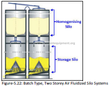
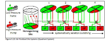
Such systems follow the concept of the fully agitated mixer. For that purpose compressed air is introduced
through a permeable media covering the silo’s bottom. Aeration causes the cement raw meal to behave as
a liquid. By variation of the airflow through the raw meal bed the individual particles are forced to move
relative to each other what result in efficient homogenization (Fig-5.23). As to achieve a variation of the
airflow through the raw meal bed the silo bottom is divided into segmented areas, typically into quadrants
or octants. Typically two air compressors are installed for aeration air supply. Homogenizing air is supplied
at a high rate and a high pressure into the selected homogenizing sector (one quadrant or octant) and
creates by this an extremely active, low-density column of raw meal. At the material surface this upward
moving blending column spills onto denser, downward moving material located over the aeration sectors.
Air supply to the aeration sectors is at much lower rate and at lower pressure. Active homogenizing aeration is switched systematically at regular time intervals by means of a special valve sector by sector.
The design of storage silos is quite similar to the design of continuous blending silos, which will be
discussed later
Fluidized homogenizing silos are designed according two design concepts, as batch-type silos or as
continuous-overflow type silos.
5.3.1.1 Batch-Type Silo Concept
Homogenizing effect: The homogenizing effect of air-fluidized silo system when operated in batch-wise
mode may be as high as 15:1. Air fluidized silo systems are thus most efficient in raw meal beneficiation
but one has to accept small compositional differences between the single batches. These differences
become smaller and closer for raw mix composition by component adjustment at mill inlet.
Energy consumption: Energy consumption with air-fluidized silos is in a range of 0.7-1.0 kWh/t, thus
important energy consumers. Nevertheless batch type operation of homogenizing silos may be optimized
regarding power consumption just by limiting compressor run-time to the minimum required for achieving
a sufficient compositional uniformity. It is often observed that compressor run-time is excessive without
that raw meal quality can be further improved.
5.3.1.2 Continuous-Overflow Concept
Homogenizing effect: The continuous-overflow operation mode was developed as to overcome the step
type quality changes common for batch-type silo systems. Nevertheless one has to accept a slightly
reduced homogenizing efficiency due to short-circuit product leaving the silo immediately without being
homogenized.
Energy consumption: With the compressors permanently running energy consumption of overflow-type
silos is in a high range of 1-1.5 kWh/t, thus significantly higher compared to the batch-type silos.
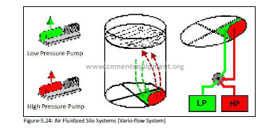
The Vario-flow silo concept (fig-5.24) is a further development of the overflow silo concept, was developed
as to reduce system energy consumption. Again the silo bottom is divided in quadrant areas but each of
the quadrants is in addition divided into a homogenizing and an aeration area. By this air supply may be
reduced what results in reduced system energy consumption. The homogenizing effect is similar as with a
conventional overflow system and the energy consumption is about 0.9 kWh/ t.
Valuation of the air-fluidized silo concept can be summarized in these four points:
1) Air fluidized silos are most efficient raw meal homogenizing system.
2) Very high energy consumption, when operated in a continuous-overflow mode.
3) Its application is limited to capacities of about 2000 t corresponding to 3000 t/d clinker production lines.
4) High investment.
Development of the air-fluidized silo concept has to be seen in context with the introduction of the dry
process in Cement Industry. At that time efficient raw meal blending was indispensable as a consequence
of the non-availability of efficient raw material preblending systems. The air-fluidized silo systems lost
ground in favour of continuous blending silos (i.e. inverted cone type gravity systems) with the
introduction of efficient preblending systems. New air fluidized homogenizing silos will hardly be installed
anymore in Cement Industry.
Still operational air fluidized homogenizing silos need not to be modified at all costs. But there operating
cost may in many cases be reduced by optimizing the homogenizing sequence. In that respect batch-wise
operation at shortest homogenizing time is preferred to a continuous-overflow operating mode.
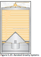
5.3.2 Aerated Gravity Systems
Aerated gravity systems aim at raw meal beneficiation and intermediate storage in one common silo. The
system follows the concept of a blender. For that purpose the raw meal is fed into the silo in horizontal
layers. When reclaiming meal from the silo a funnel will form on top of the discharge point at the product
surface. The declining funnel surface cause blending of particles originating from different layers when
sliding down the slope to into the transport channel (fig-5.25).
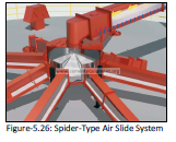
Horizontal layering of the raw meal is achieved while feeding the silo via a spider-type air slide system (fig-
5.26). Cement raw meal activation for discharge is achieved by slight aeration. For that purpose
compressed air is introduced through a permeable media covering the silo bottom. The silo bottom itself is
divided into segmented areas, the number of which is a function of the silo diameter. Aeration air is
supplied at a low rate and a low pressure into the selected aeration sector for raw meal activation. This air
leaves the silo together with the activated raw meal; it will not penetrate into the raw meal column on top
of the activated sector. Aeration is switched systematically by means of a special valve sector by sector.
The blending potential of the aerated gravity silos is limited compared with that of air-fluidized
homogenizing silos.
Aerated gravity silo systems are designed according to three concepts:
1) As inverted cone silos.
2) As central chamber silos.
3) As multiple-outlet silos.
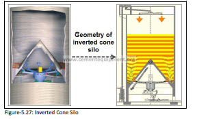
5.3.2.1 Inverted Cone Silos Concepts
The inverted cone silo (fig-5.27) represents the pure concept of the aerated gravity silo. The silo is (as said
by its name) equipped with a huge inverted cone covering most of its centre bottom area. The remaining
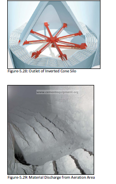
annulus is divided into segmented areas that are covered by open air slides; each sector is equipped with
its own outlet (fig-5.28). Raw meal is activated predominantly at the silo’s circumference by sequential air
supply to the individual sectors, avoiding by this the formation of huge zones of stagnant product. The
blending effect of this silo type is 5:1 (as maximum) and its energy consumption is about 0.1-0.2 kWh/t.
Inverted cone storage silo system has emerged as one of the most popular designs in the Cement Industry
due to several benefits like up to 99% emptying efficiency (fig-5.29), low power consumption and
availability of multiple outlets. Only a small ring of the Silo bottom is covered with fluidizing units and divided into several sections. At any given time only selected section is activated by means of low capacity
roots type blower and other sections are activated in a cyclic manner. Several discharge gates placed at the
circumference of the silo opens one after the other making the material flow towards the outer shell. The
material moves downwards at the silo wall avoiding the formation of incrustations and dead zones on silo
wall.
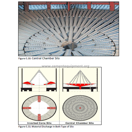
5.3.2.2 Central Chamber Silo Concept
The central chamber silo configuration (fig-5.30 & fig-5.31) refers to a concept that uses the inverted cone
as a centre chamber for additional reduction of residual compositional short-term variations. The annulus
is divided into segmented areas that are covered by open air slides as for the inverted cone configuration.
Again raw meal is activated by sequential air supply to the individual sectors. Design of the central
chamber differs in shape (conical or cylindrical) and volume. Compressed air is introduced for airfluidization
through a permeable media (open airslides) covering the chamber bottom that is typically
divided into quadrants. The aeration sequence for the central chamber is similar to that of air-fluidized
silos as discussed before. The blending potential of a central chamber silo is slightly better compared to
that of a simple inverted cone silo. The blending effect in this type of silos is 5:1
And the energy consumption is 0.3 kWh/t.
5.3.2.3 Multiple-outlet Silo Concept
Multiple-outlet type gravity silos follow the concept of blending the raw meal while it is discharged via
different outlets at different rates. 5:1 is the silo blending effect and 0.3 kWh/t is the energy consumption
of this type of silos. This type of silos is available in various configurations:
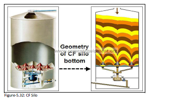
5.3.2.3-a FLS Controlled Flow (CF) Silo Concept
The silo bottom of the CF silo (Fig-5.32) is divided into seven identical hexagonal sectors, each of which has
its centre outlet covered by a pressure relief cone made of steel. Each of the hexagonal sectors is
subdivided into six triangular segments all equipped with open aeration boxes. Raw meal extraction
follows a sequence where three segments positioned at three different outlets are aerated at a time. From
the outlets it is conveyed at different rates to the central mixing tank installed below the silo. The aeration
sequence is cyclic in a way that all the 42 segments will be activated once within about 15 minutes.
5.3.2.3-b Fuller-Kovako Random Flow Silo Concept
Again the silo bottom of the random flow silo is divided into a number of sectors. In addition these sectors
are subdivided in six discharge zones and equipped with a closed collecting airslide. Each discharge zone
has its pick-up point to the collecting airslide from which the raw meal is transferred to the centre mixing
tank installed below the silo. Selective aeration is the means by which raw meal is discharged out of three
different silo areas at a time. Again aeration sequence is cyclic. The concept can easily be applied for
upgrading existing fluidised blending silos.
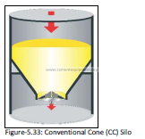
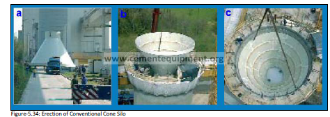
5.3.2.4 Conventional Cone Silo Concept
The conventional cone (CC) silo is aerated gravity technology designed by Claudius Peters (fig-5.33 & fig-
5.34); it is especially suited to small silo units. It is basically a conventional cone silo where the lower
section of the cone is cut and replaced by an aerated CC standard bottom. Owing to its compact design,
this type of silo bottom needs less fluidization equipment and therefore consumption of less energy
compared to a conventional silo construction. It guarantees excellent discharge characteristics even for
those materials which do not fluidize so well. Other bulk materials like Gypsum, Quicklime, Lime Hydrate
and others can also be stored and discharged in the CC Silo. The sectors are alternately aerated at pre-set
times ensuring almost complete discharge of the silo. This process does not affect the filling procedure.
The airslides arranged on the silo bottom support the discharge by fluidizing the stored material. Then the
fluidized material flows along the inclined airslides to the outlets by means of gravity. The size of the sector
is optimized so that the flow is maintained while ensuring bridging does not occur.