Quarrying In the cement industry
[wpecpp name=”package + Updates forever” price=”250″ align=”center”]
2.0 Quarrying
In the cement industry quarrying is the mining method for the production of raw materials in the
process of making cement. Quarrying describes the surface mining of rock whereas ‘open pit’ mining
describes the surface mining of minerals. Discontinuous mining systems such as scraping, ripping
and dozing, and blasting are commonly practiced in limestone quarries. Continuous mechanized
mining systems with bucket wheel or chain excavators are used where the deposits are consistent
and soft such as chalk. Quarrying is the breaking of the rock in a safe and economic way and
transporting the result to a plant for further reduction in size.
Blasting is the most widely used method to excavate limestone for cement production as the rock is
usually too hard to be ripped or dozed. This involves the drilling of holes in the rock, placing a
predetermined charge of explosive in each hole and detonating it. The result is a pile of broken rock
which then has to be removed to the cement plant. As it is not economic to break each piece of rock
to the required dimensions in the blasting process the rock is further reduce in size before being
transported to the cement plant storage silo. This further reduction is accomplished by means of a
crusher system. To obtain optimum results from the quarry operation the rock to be blasted has to
be matched to the explosive and the drilling parameters.
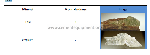
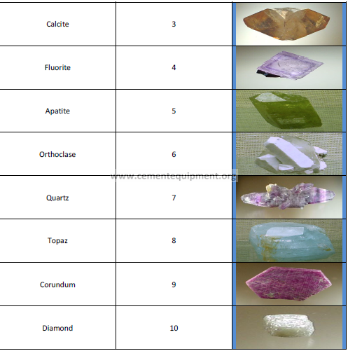
Rock hardness is classified by using Mohs scale of hardness. This lists ten rocks with differing degrees
of hardness in an ascending order. The rocks used as standards, their Mohs’ hardness and basic
classification are to be found in (table-2.1). Limestone with a high percentage of calcium carbonate is
one of the sedimentary rocks found in the crust of the earth. It has an average Mohs’s hardness of
about 3.3. This means that it is usually necessary to blast limestone to free it from the surrounding
rock.
2.1 Drilling
Bench drilling is a term for designating the method where surface holes are drilled for blasting
towards a free face. Blasted rock then has ample space in which to expand. Bench heights vary
between 5.0 meters and 30.0 meters depending on the thickness of the formation, however the
limiting factor in the height of the bench is usually that of safety or hole diameter. Safety can be the
inherent stability of the formation, the greater the stability the higher the bench and hence the
longer the drill hole. An increase in the stability of the formation can be achieved by the use of
inclined drill holes. This creates an artificial slope at an angle between seventy and eighty degrees. If
a failure of the bench occurs the rock will tend to roll down the incline face and not drop thus
confining loose rock. Larger hole diameters mean that longer holes can be accurately drilled. Toe
position of a hole is important if successful breaking is to occur. With hole diameters of 64 mm or
less a hole drilled over 20 meters is likely to wander from the line. Quarry operations usually use an
intermediate diameter drillhole of between 64 mm and 165 mm although very large quarries can
have hole diameters of up to 440 mm.
2.2 Drilling Methods
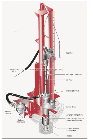
2.2.1 Rotary Drilling
Most commonly used in soft-medium rock masses that have an average Mohs’ hardness of less than
about four. This is a drilling method that was originally used for oil well holes (fig-2.1). In rotary
drilling energy is transmitted via a drill rod which is rotated at the same time as the drill bit is forced
down. The bit is rotated continuously at between 50 and 90 revolutions per minute. Downward
thrust is achieved by the weight of the machine. The relationship between feed force and rotation
rate determines drilling efficiency. Energy losses in rods are minimal in rotary drilling. All such drilling
requires high feed pressure and slow rotation but the relationship varies with rock type. Softer rock
requires lower pressure and higher rotation speed and vice versa.
2.2.2 Percussion Drilling
Practiced where the rock is hard to very hard and abrasive. This type of drilling is divided into two
methods.
2.2.2.1 Top Hammer Drilling
A shank adapter is hit repeatedly by a piston in the drilling machine which creates a shock wave that
travels down the drill string to the bit (fig-2.2). Energy is discharged against the bottom of the hole
and the surface of the rock is crushed. Air travelling down the center of the drill string flushes the
resulting chips out of the hole. The whole drill string is rotated and crushes each segment of the hole
face in turn. Drilling machine and string are arranged on a feed usually either chain or screw, and the
feed force can be kept in contact with the hole bottom by adding extra drill rods when the feed
mechanism reaches the limit of its travel.
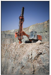
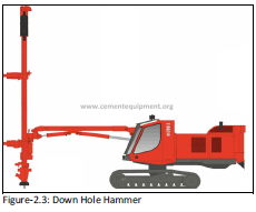
2.2.2.2 Down Hole Hammer
The hammer and its impact mechanism operate down the hole, the piston strikes directly on to the
bit (fig-2.3). No energy is therefore lost through transmitting the shock wave down a drill string. The
drill tubes carry the compressed air for hammer and flushing.
2.2.2.3 Overburden Drilling
A new quarry operation is fortunate if the rock to be blasted is fully exposed on surface. In the
majority of cases it is overlain with soil and weathered, powdery rock called collectively overburden.
This must first be removed before the rock below can be removed. In cases where overburden is soft
dozers and rippers can accomplish the work. Conventional methods as described above are not
suited to these ground conditions and problems could be experienced with stuck rods. A special drill
that has casing tubes with its own ring bit in addition to the normal bit are manufactured for these
conditions. This specially designed drilling rig has the following attributes:
1) Drilling will be continuous through varying ground conditions.
2) If stopped drilling can continue in loose ground easily.
3) The hole is prevented from collapsing when the bit is removed.
4) Flushing is efficient and rotation torque is high.
2.3 Drilling Parameters
Determining the size and number of blastholes as well as the drill rig required to drill them is based
on many different parameters, like:
1) Capital: Cost outlay required to purchase rigs.
2) Nature of the Rock: Jointing, bedding planes, a smaller hole diameter will permit better
distribution of the explosive in the rock and a better explosive efficiency. A larger hole diameter
means a larger burden and more concentration of the explosive. Although drilling costs would be
lower, fewer joint bound blocks would be intersected by drill holes resulting in excessive secondary
blasting costs.
3) Fragmentation Size Distribution: Efficient drilling designs combined with the correct choice of
explosive result in better fragmentation. Correct collaring of holes improves the whole quarry
efficiency. If holes are drilled out of position or of the incorrect length then fragmentation is going to
be poorer. Too long holes will result in wander of the toe of the hole with resulting increases in
burden and spacing again resulting in poor fragmentation and overall explosive performance.
4) Monthly tonnage Requirements: Larger hole diameters are used where there is a greater tonnage
requirement.
6) Vibration and Airblast: Smaller hole diameters imply a smaller mass of explosive per delay
reducing the level of ground vibrations.
2.4 Drilling Definitions and Equations
2.4.1 Borehole Diameter
This is important to obtain maximum fragmentation at the lowest cost. The cost of drilling per cubic
meter blasted decreases as the hole diameter increases. However too large a diameter can cause
problems with resulting airblast and flyrock if the bench height is too low. Excessive jointing at small
intervals in the rock can cause a fragmentation problem if a large hole diameter is selected. For best
fragmentation control the appropriate bench height to borehole diameter is 0.12 to 1 (in meters and
mm).
That is:
0.12 * D = H
Where;
D = borehole diameter in mm
H = bench height in meters
2.4.2 Burden
This is considered the most critical variable in the design of surface blasts. It is defined as the
distance from a borehole to the nearest free face at the time of detonation. In planning, the burden
is taken as the distance at right angles to the free face, from the free face to the first row of
blastholes. Burden is a function of the charge diameter and therefore also depends on the drillhole
diameter.
B = (25 to 35) * E
Where;
B = burden in meters
E = explosive in hole, diameter in meters
2.4.3 Spacing
Is the distance between adjacent boreholes and is measured parallel to the free face. The optimum
spacing to burden ratio is between 1 and 1.3. Too small a ratio leads to holes not breaking out with
resulting flyrock and ground vibration problems. Too large a ratio has the effect of increasing
oversize as the blastholes break individually to the free face.
2.4.4 Bench Height
Is the distance measured vertically from one level floor of a quarry to the next up or down. For a
successful design it is important that the burden and bench height are reasonably compatible.
The minimum is: H = 2 * B
Where;
H = bench height in meters
B = Burden in meters
If the bench height is low and the burden and blasthole is large then an excessive percentage of the
borehole is taken up with stemming. Very high benches become a danger for personnel working
beneath them.
2.4.5 Subdrill
The distance drilled below the level of the bench floor necessary to be certain that on blasting the
toe of the holes breaks out.
2.4.6 Vertical and Inclined Holes
Drill holes are drilled either at an angle to the vertical in the direction of the free face or vertical. In
addition there can be a reduced explosive cost due to increased burden. There is also less risk of
backbreak and toe problems. However; inclined drilling needs closer supervision in order to achieve
good results. If the hole is under burdened then flyrock is more likely from blowouts.
2.4.7 Drill Hole Deviation or Wander
The drill bit and drill string can be deflected from its planned straight course after collaring.
2.4.8 Collaring
Collaring is the start of the hole where the drill bit is placed on a marked position and drilling
commences.
2.5 Drilling Patterns
Blast holes are drilled to a pre-planned pattern which will determine the number of holes and drilled
meters & cubic meters of rock to be blasted. Drilling plans are either made using prepared drilling
tables for certain parameters or they can be made especially with a desired result in mind. The most
common patterns are:
2.5.1 Square
Equal burden and spacing
2.5.2 Rectangular
Burden is less than the spacing. It is easily marked out and easy to collar accurately.
2.5.3 Staggered
Spacing to burden ratio may be one is more usually greater than one. The holes in alternative rows
are in the middle of the spacings of the row in front. Ideally holes should be drilled in a triangular
pattern where the spacing to burden ratio is 1.15. This equilateral triangular pattern provides for the
optimum distribution of the explosive charge for any particular hole diameter throughout the rock.
In this way the cost of drilling and blasting can be optimized.
2.6 Blasting
Blasting is an intermediate step in the process of quarrying. Choosing the correct explosives is one of
the most important decisions influencing the design and operation of a quarry. It cannot be taken in
isolation as other factors such as rock type and hole diameter. The major objectives of a blast are to
suitably fragment the rock and to displace it such that it is easy and safe to load out. Once a blast has
been initiated it is uncontrollable and cannot be repeated if incorrect. The greater the effort put into
the planning and preparation the better the results will be.
2.6.1 Breaking Process
An explosive is a chemical compound or mixture ignited by shock, impact or friction. When ignited it
decomposes rapidly as a detonation. There is a release of heat and large quantities of high pressure
gases which expand rapidly with sufficient force to overcome confining forces such as the rock
around the drill hole. In commercial blasting the energy released by the detonation manifests itself
in four ways: rock fragmentation, rock displacement, ground vibration, and airblast.
2.6.2 Explosive Properties
Each explosive has certain different characteristics or properties. Here are some of the major
properties:
1) Velocity of Detonation: The speed at which a detonation wave travels through a column of
explosives.
2) Density: Specific gravity, the standard being water.
3) Detonation Pressure: The pressure immediately behind the detonation front.
4) Energy: A measure of the potential of an explosive to do work.
5) Strength: The ability of an explosive to work.
6) Sensitivity: A measure of the minimum energy required to initiate the explosive.
2.6.3 The Process of Detonation
In a detonation the chemical reaction moves through the explosive material at a velocity greater
than that of the speed of sound through the same material. The definitive characteristic if this
chemical reaction is that it is initiated by and supports a supersonic shockwave proceeding through
the explosive. Deflagration of an explosive occurs when the shockwave moves too slowly to produce
significant shock energy. Generally explosives with a lower VOD (velocity of detonation) tend to
release gas pressure over a longer period than those of higher VOD. These lower VOD explosives
have more heave important in areas where material movement is needed. In commercial explosives
significant chemical reactions occur behind the primary reaction zone and affect the explosive
performance. This is due in part to the need to make explosives safe to handle. The majority of
products are gases at high temperature and pressure. In the order of 4000 °C and 20 to 100 kbars,
these gases expand rapidly and produce the shock wave in the surrounding medium which in turn is
transmitted into the rock around the borehole. Shock provides the energy for fragmenting the rock,
the heave energy to move the fragmented blocks to form the muckpile.
An explosion in a drilled hole is closely followed by the shock wave passing through the rock and
stressing it first in compression and then in tension. Tensile forces cause small radial cracks to
develop from the hole which are subsequently expanded by the explosive gases entering them. The
free rock surface starts to move forward unloading the pressure. The tension increases in the
primary cracks which expand to surface and complete the loosening of the rock.
2.6.4 Effects of Blasting
2.6.4.1 Fragmentation
It is the extent to which rock is broken into pieces by blasting. Degree of fragmentation desired is
dependent on the loading and crushing equipment and use of the product. In the economics of
blasting cheaper means coarser fragmentation but this requires larger loading equipment to handle
the oversize. Bigger machinery is designed for bigger tonnages not to load out oversize. Every quarry
manager should consider the increased cost of drilling and blasting against the profitability of an
increase in output obtained by an increase in fragmentation in order to obtain the lowest cost per
unit for the whole operation. Many factors affect fragmentation. The major ones are:
2.6.4.1a Terminology
‘Fragmentation’ is a general and highly subjective term in which ‘good’ does not necessarily mean
‘small pieces’. Depending on the chief requirement of the operation and the final product
management will focus on one of the following:
1) Fines: Rock particles of suitable chemical quality but too small for processing or sale. These
represent an effective loss of reserve and production. Fines incur costs in production and additional
costs in storage or disposal if not used. In a limestone quarry the fines can either be represented as
increased capacity to the plant, they need no further reduction in size by the crusher or as the
overuse of explosive energy negating the use of the crusher.
2) Oversize: Rock particles too large to be handled by the available loading or crushing equipment.
This causes delays in production while being moved out of the way and increased maintenance costs
to loading equipment not designed to handle them. They generally increase working costs, the
majority have to be re-broken and reduce the safety of both workers and equipment. It is normal
practice for management to measure the blast purely on the percentage oversize contained in the
muckpile and to disregard the percentage fines.
3) Mean Size: Defined as the mesh size through which 50 % of the muckpile can pass. While not as
obviously critical as the above it provides a meaningful guide to ease of digging. Being at the
midpoint of the size range ‘mean size’ is not as sensitive to small variations in the ‘oversize’. For
example a 100 % increase in boulder count may represent less than a 1 % increase in mean size.
2.6.4.1b Quality of Explosives
The product of strength per unit weight and charging density known as strength per unit volume,
determines the effectiveness of different explosives in breaking rock.
2.6.4.1c Rock Characteristics
In jointed rocks the correct direction of blasting is important. In hard, solid and slightly fractured
rock the extent of the crushed zone around the blasthole is dependent on the charge per hole
length.
2.6.4.1d Blasthole Loading
Proper fragmentation occurs when there is enough force in the compression wave to travel to the
free face and back. The quantity of explosives is enough to fragment the rock. If not enough
stemming is placed in the collar of the blastholes then on detonation gasses will escape from the
holes reducing the efficiency of the explosives.
2.6.4.1e Drilling Accuracy
If drilling accuracy is suspect the planned drilling parameters will have to be decreased to maintain
explosive efficiency.
2.6.4.1f Timing & Pattern
Better breaking has been found when using a delay interval in milliseconds of about ten times the
drilled burden in meters. The interval should be chosen after taking into account the burden and
spacing and the number of holes to be blasted. In any blast the stemming area produces the most
oversize as there is usually a lower distribution of explosives than in the rest of the blast. To improve
fragmentation, the quantity of explosive in the collar area can be increased in a number of ways. The
column charge can simply be increased. Smaller diameter and shorter length holes can be drilled in
between the main holes and charged with a small quantity of explosives. A separate charge can be
introduced into the stemming, known as decking.
2.6.4.2 Muckpile
This is defined as a pile of blasted rock that is to be loaded for removal. The ‘throw’ or movement of
the rock from the blast increases as the specific charge increases and may be controlled by varying it.
As blasting proceeds in multi row conditions the muckpile in front of the face will gradually lie closer
to it. The shape of the muckpile is influenced by several factors.
2.6.4.2a Drill Hole Angle
An inclined hole will project the rock further than a vertical hole resulting in a flatter outline of the
blasted rock.
2.6.4.2b Surface Timing
Diminishing the burden or increasing the hole size will result in the rock moving further and giving a
flatter muckpile. The type of loader used in the quarry will determine the most efficient muckpile
outline. A front end loader will find it easier to load out a flatter muckpile and a face shovel a
steeper one.
2.6.4.2c Free Face
It is assumed that blasting cannot be effective unless a free face exists towards which movement can
take place. This is not so, the free face improves the efficiency of the breaking but does not prevent
fragmentation from occurring. Choked faces inhibit movement and cost more in explosives
consumption but probably do not significantly affect the fragmentation. In solid ground without a
free face, high powder factors are necessary for good fragmentation. A degree of movement is
enabled through the porosity of the rock and voids left by previously fired holes. The practice is not
common as other factors mitigate against it namely ground vibrations, airblast and flyrock.
2.6.4.2d Fragmentation Analysis
The only sure method of obtaining a muckpile fragmentation analysis is to screen the whole
muckpile. Any method developed would also depend on this for an absolute correlation. This is
clearly impossible and all methods therefore have an unknown degree of error. This can be
minimized by working on comparisons, the error then being constant. With time and experience the
error can be assessed and almost eliminated.
2.6.4.3 Ground Vibrations
The trend towards larger holes and bigger blasts and an increased population has highlighted the
problems of ground vibrations. Damage due to old age or settlement of a building is very hard to
distinguish from blast damage. The main criterion is to reduce the level of vibration to such an
extent that complaints are minimal. At the same time good public relations will ensure that people
living locally will feel reasonably well disposed to the quarry. When an explosive detonates in a hole
it generates an intense stress wave on both transverse and longitudinal wave motions. This motion
crushes the rock around the hole up to about one drillhole radius and permanently distorts and
cracks it for several more. Most of the energy is spent on shattering the rock but because of the
imperfect nature of the explosive, some of the energy is transmitted through the ground as vibration
in the form of elastic compression waves. This represents a transfer of energy from one point in the
rock to another. Initially there must be some displacement of the rock as certain forces act to
displace it from its equilibrium position and introduce new energy to the system.
2.6.4.3a Source of Ground Vibrations
If the rock does not exhibit an elastic response, energy is absorbed by it and only dampened waves
come from the blast area. If elastic response is exhibited then the action of the blast causes nearby
portions of the rock to oscillate about their rest positions similar to a spring. Oscillatory conditions
are set up and the disturbance is transmitted from one element to the next as from the rock to a
building. During wave motion there is no bulk movement of matter. The transmission of waves is
affected by distance from their source. The rock through which they travel is never perfectly
homogeneous; it contains deformities such as joints, bedding planes and different rock types. Total
energy of a ground motion wave generated varies directly as to the mass of the charge detonated.
As it travels outward from the inception point; the volume of rock affected by the compression wave
increases and the peak ground motions decrease. The ground motion wave of a column charge of
explosives where the length to diameter ratio is greater than 6, takes the form of an expanding
cylinder. The volume of this compression cylinder varies as the square of its radius. Thus the peak
level of the ground motion is inversely proportional to the square of the distance from the blast. In
the majority of quarries the detonation of a borehole takes the form of a cylindrical blast. For
example a 104 mm hole has to have a minimum single charge length of 0.625 meter for it to be a
cylindrical charge.
2.6.4.3b Defining Peak Particle Velocity
The empirical scaling formula relating peak particle velocity (PPV) to scaled distance has been
developed from actual field results. Scaled distance [d/(W^1/2)] combines the effect of total charge
weight per delay [W] on the initial shock level with increasing distance [d] from the blast. The
formula contains two site factors [K] and [m] which allow for the local influence of the rock on the
rate of peak particle attenuation. Geometric progression is included in the slope exponential [m] in
the following equation:
V = K*(d/ (W0.5)-m
Where;
V = Maximum PPV (mm/sec)
d = Distance from blast (m)
W = Mass of explosives per delay (kg)
K & m = Slope of graph
d/ (W0.5) = Scaled distance for a cylindrical charge
Site factors are determined from the logarithmic plot of PPV verses scaled distance. The graph is
drawn and the best line representing the data is inserted. Work done by the US Bureau of Mines
implied that the best damage indicator is PPV as a function of frequency below 40Hz. A number of
studies have correlated levels of PPV with resulting damage and an example of the levels is shown in
table-2.2
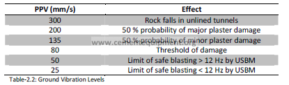
The intensity of seismic waves that can be tolerated by structures varies as to the method of
construction. A steel reinforced building can withstand a higher level of motion than a privately
owned house built of brick. Plaster is commonly used on the inside walls of houses. It is relatively
weak when compared to other building materials and is used as the basis for damage criteria.
2.6.4.3c Techniques to reduce Vibration Levels
To minimize the level of ground vibrations it is easy enough to reduce the charge per delay. This
however may not be practicable as it implies reduced production. Several other steps may be taken
to reduce levels of vibration:
1) Blast Design: This should give maximum relief of burden. Internal free faces in the blast can reflect
compressional waves.
2) Powder factor: An excessive powder factor can increase ground vibrations and may cause
excessive throw of the muckpile. Vibration levels can also be increased by an insufficient powder
factor. It delays and reduces the effect of rarefaction waves reflected from free faces.
3) Spacing to Burden Ratio: To be greater than one. Overburdening of holes can cause them not to
break out to the free face. This results in excessive explosive energy used as shock waves through
the rock.
4) Accurate Drilling: Poor drilling can over or under burden the holes with the same results as for
poor spacing to burden ratios.
5) Sub Drill: The toe of a drill hole is the most confined area and has the most difficulty breaking out.
Over drilling increases the amount of sub drill and therefore the vibration levels.
6) Adequate and Accurate Delays: A long delay period between holes will guarantee that they do not
detonate simultaneously. Shock waves can be reinforced by waves from subsequent holes in a line
detonating if the delay interval is insufficient. Very little delays in a blast result in a high mass per
delay. Studies have shown that millisecond delays in commercial detonators are not very accurate.
This can result in close timing or in extreme cases an overlap.
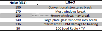
2.6.5 Airblast
The compressional wave in air either from unconfined explosives or by indirect action of a confining
material subject to explosive loading is known as airblast. Noise is that portion of the spectrum in
the range 20 to 20,000 Hz. Airblast at levels below 20 Hz is known as concussion. Large burdens
typically found with large diameter boreholes means that the airblast contains a considerable
amount of energy at frequencies below 20 Hz. Low frequencies can damage structures directly but
more often causes higher frequency vibrations in windows and doors.
2.6.5.1 Atmospheric Conditions
Atmospheric conditions may affect the intensity of the noise at a distance from the site of the blast.
The speed of sound in air varies at different altitudes and temperatures. In addition the wind speed
will affect the distance that sound waves carry. Normally the air temperature decreases with altitude
the adiabatic lapse rate at a rate of about 2.0 degrees centigrade for 300 meters increase in altitude.
An inversion, a decrease in temperature with altitude, will cause noise to be reflected back to earth
causing excessive noise levels to be heard in unexpected areas. As the time of day can determine
weather conditions, inversions occurring more often in the morning, blasting times should take note
of this fact to minimize possible complaints. The effect of wind on noise levels is greater during the
cold months because of the higher wind speeds. This helps to prevent inversions occurring..
2.6.5.2 Minimizing Airblast
Minimizing airblast not only depends on the correct weather, a clear day with light wind but also:
1) Use of Adequate Stemming: Confine the blast stemming blown from the hole results in higher
noise levels.
2) Secondary Blasting: Not using mudblasts, breaking rocks with a lay-on charge which is covered
with mud.
3) Sequential Blasting: Sequence of blast must proceed in a proper order. Out of sequence shots
cause excessive airblast.
4) Time of Day: Scheduling of blasting operations when people are busy. Rush hour generates a high
level of noise which will cover blasting noises.
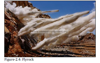
2.6.6 Flyrock
This is the undesirable throw of rock from a blast (figure-2.5). Rocks have been thrown many
hundreds of meters and caused both material and bodily damage. It is probably the biggest cause of
personnel injury and property damage in the whole blasting operation. Flyrock is caused by a
number of factors:
1) Overloading of holes or insufficient burden.
2) Poor quality stemming.
3) Incorrect timing of surface delays.
Regardless of the care taken with a blast flyrock is always possible and every precaution taken to
prevent damage. All blasting personnel must take cover when the blast is detonated. The direction
of the blast must be away from any structure which could be damaged. A quarry situated close to
built up areas has to prevent flyrock at all costs. Good blast design is the best method of minimizing
this hazard.
2.7 Loading & Mucking
The methods of loading and hauling in quarries can be divided into four categories:
1) Continuous mining systems such as the bucket wheel excavator.
2) Other non-blasting systems such as ripping and bulldozing or scraping.
3) Haul road, using loaders and trucks and a ramp to exit the quarry.
4) In pit crushing in which a loader or face shovel supplies a mobile crusher.
Equipment to load and transport rock is dependent on the hardness of the rock to be quarried. Soft
rock or overburden can be removed without the need for blasting by ripping and dozing with
specialized machinery. There are both discontinuous and continuous systems for the removal of rock
without blasting.
2.7.1 Selection of Equipment
Initially the quality and quantity of any deposit must be established to enable a decision to be made
as to the mode of operation. Seismic wave prospecting can be used to discover the hardness and
extent of the deposit. This data is compared to previous data obtained in the exploration of other
deposits. For many commonly found rocks a range of rippability values in terms of their seismic
wave velocities have been tabled with a fair degree of accuracy.
Depending on the planned tonnage to be excavated per year and the consistency of the deposit,
both physical and chemical over large areas determines the equipment to be purchased. Large
tonnages of relatively soft material with a shallow deposit favor a continuous mining system. Smaller
production levels with varying quality of limestone favor a more mobile system such as a truck and
shovel. The final selection must take into account overall economics and will be based on balancing
the following against each other:
1) Capital Cost
2) Technical Suitability
3) Maintenance and Repair
4) Manufacturers Acceptability
2.7.2 Non-Explosive Mining
There are several systems of exploitation that do not require the use of explosives. They are
generally confined to quarries that have soft rock with a uniform quality over large volumes with few
inconsistencies permitting continues mining machine to advance in a systematic manner with little
or no manoeuvring. Chalk or Marly Limestone is good examples of these softer rocks that are
excavated as raw materials in the manufacture of cement. Soft rock permits the material to be
exploited without it first having to be drilled and blasted. The rapid advance of mining technology
has developed machines that have applications in harder rocks but to be cost effective require a high
tonnage output. Capital cost of most continues mining machines are too high to warrant their use in
what is essentially a small tonnage per year operation at a cement plant.
2.7.2.1 Continues Mining Systems
Excavation of raw material can be accomplished by the use of a Bucket Wheel Excavator (BWE) or
Bucket Chain Excavator (BCE) or a newly developed Surface Miner. If considered as an alternative to
conventional exploitation methods the capacity of the plant has to be sufficient to accept the high
tonnages involved some BWE’s will move 100’000 mts per day. There also has to be continues
system of removing material to the plant if the machine is to have a high utilisation time. This usually
takes the form of a conveyor belt. Any alternative, such as truck or rail systems can quickly result in
the excavator waiting for loading equipment. Non-continues systems of transport require detailed
planning for them to be used to their fullest and minimise downtime of such a machine. Optimum
operation is normally achieved by building an excavating machine and a complete transport system
specifically for the required application. The advantage of continues mining system is that it reduces:
1) Dependence on diesel fuel, a primary fact if this has to be imported.
2) Labour complements; although it may be necessary to have a fleet of support vehicles such as
bulldozers, personnel carriers and cranes to service continues miner.
3) Noise, dust and air pollution in the operation of winning rock.
4) Haul road maintenance.
5) Power consumption.
Development of light weight machines, for example, tyre mounted bucket wheel excavators or
surface miners which are considerably cheaper to purchase and have lower capabilities has made
the use of these machines in our industry in the future more likely.
2.7.2.2 Semi-Continues Systems
Other non-explosive systems of winning material find more favour due to the ability of such a
system to relocate and their relatively low capital cost per unit. Examples of these are the use of a
shovel to load material directly into a haul truck or the use of a ripper on a bulldozer to loosen the
rock and a load haul system to move material to the crusher. This enables a plant to have the
operational flexibility provided by the use of multiple mobile equipment while not having to invest in
new mining systems.
2.7.3 Haul Road
This involves building ramps up or down the side of quarries and using dump trucks and loaders to
haul rock from the blasted area to the primary crusher, usually situated outside the quarry. It is a
very versatile method of operation and is suited to any terrain from flat ground to mountainous and
any size quarry. This method of moving rock to the crusher is the most common in small to medium
quarries. The trucks will range in size from 20 to 80 tons. Loaders range in bucket capacities from 3
to 13 cubic meters based on the specific gravity of the rock to be loaded.
2.7.4 In Pit Crushing
Transport between the loader and the fixed crushing plant is nearly always by a discontinuous
transportation method, trucks. This can be considered a disadvantage in that either end of the
transport system is in continuous operation. As the quarry faces are always advancing the site of the
crusher does not remain optimum for long. To facilitate this; an ever increasing number of trucks is
required to maintain production with associated increased costs. An answer to this problem has
been to install in-pit mobile crushers which considerably reduce the need for trucks. Rock is loaded
from the muckpile to the primary crusher and is then fed to a conveyer belt to be transported to the
plant. The crusher in the quarry is usually mobile so that it can follow the advancing faces. This is
made possible by the addition of conveyor belts when the unit is moved forward. Secondary and
tertiary crushing systems are (if required) on a fixed site outside the quarry. The capital investment
to purchase a mobile crusher is higher than for an average fleet of trucks. However the savings in
manpower and increased output from the loading equipment reduce the overall working costs and
make the unit justifiable.