PURCHASE GUIDE| comparison| Experiments| for JAW CRUSHER & ROLL CRUSHER & BALL MILL
EXPERIMENT- A JAW CRUSHER
OBJECTIVES
- To study the operations of crushing using a Jaw crusher.
- To analyze the properties of particles before and after crushing.
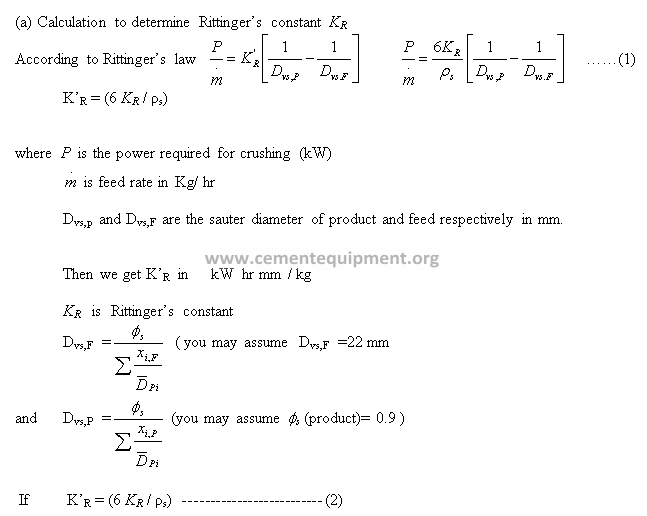
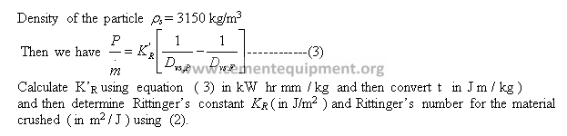
- To determine Rittinger’s Constant and Rittingers number for the material being crushed.
THEORY
Jaw crusher is used for coarse crushing (feed size: 40 mm -50 mm; product size: 2 -10 mm). The crusher has a fixed jaw and a moving jaw pivoted at the top with the crushing faces made of manganese steel. Since the maximum movement of the jaw is at the bottom, there will be little tendency for the machine to clog, though some uncrushed material may fall through and have to be returned to the crusher. Further the maximum pressure will be exerted on the large material which is introduced at the top. The machine is usually protected so that it is not damaged if lumps of metal invariantly enter, by making one of the toggle plates in the driving mechanism relatively weak so that, if any large stresses are set up, this is the first part to fail. Easy renewal of the damaged part is then possible.
Jaw crushers are made with jaw widths varying from about 100 mm to 200 mm and the running speed is about 240 rpm, the smaller machines running at higher speeds. The speed of operation should not be so high that a large quantity of fines is produced as a result of material being repeatedly crushed because it cannot escape sufficiently quickly. The angle of nip, ie the angle between the jaws, is usually about 30o. The power requirement of the crusher depends upon the size and capacity.
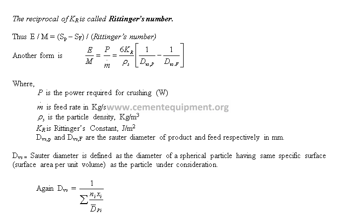
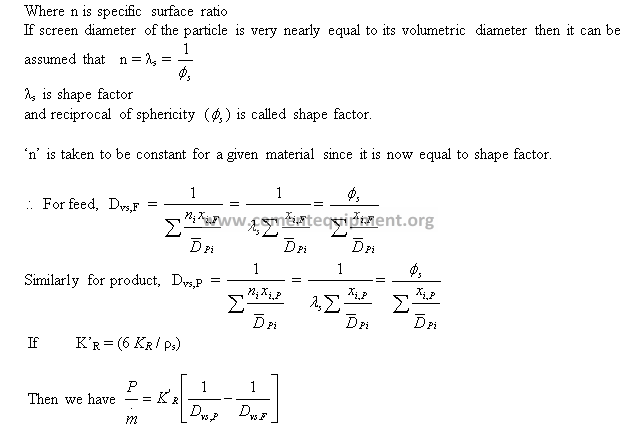
One of the laws of comminution or crushing has been proposed by Rittinger. According to Rittinger’s law, the work required for size reduction is directly proportional to the new surface created.
E / M = KR (Sp – SF)
Where,
E = energy E in Joules required for crushing M kg of material.
Sp, SF = specific surfaces of product and feed, m2/Kg
KR = Rittinger’s constant
REQUIREMENTS
Jaw Crusher, Sieve Shaker, Sieves, Weighing Balance, Feed, Stop watch.
PROCEDURE
- Prepare feed to be crushed in the jaw crusher (10 Kg feed of metal stone, 2” max size).
- Start the jaw crusher, introduce feed stones one after another into the hopper , start stop watch, note the time and number of pulses on the energy meter till the completion of crushing the entire feed material. This gives the power consumption (P2) under loaded condition.
- Run the jaw crusher in unloaded condition for the same time as in step 2, note the number of pulses on the energy meter. This gives the power consumption (P1) to run the empty jaw crusher.
- Take different sieves ( GI frame sieves with aperture size20 mm, 10mm, 8 mm, 4.75 mm BSS mesh no 6,10 and pan) and perform sieve analysis of the product from the crusher.
- Weigh the material in each sieve.
OBSERVATIONS
Type of Feed taken =———————-
Average size of feed may be assumed to be———————— (~ 40 mm)
Weight of feed taken, M = ——–kg.
Time of crushing, t = ———–sec
Number of Pulses for crushing, NP2 =
Number of Pulses for empty run, NP1 =
Feed rate = M/t = ———–( kg/sec )
Power required during crushing, P2 = (NP2 * 3600/1600)/t = kW
Power required during empty run, P1 = (NP1 * 3600/1600)/t = kW
Power consumed by material = P = (P2 – P1)*1000 = ———–( W)
DATA ACQUISITION
CALCULATIONS
EXPECTED RESULTS
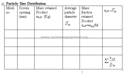
- Calculate the mass fraction xi versus average particle diameter of each fraction.
- Determine Rittinger’s constant KR (in J/m2 ) and Rittinger’s number for the material crushed ( in m2 / J ).
- Compare the Rittinger’s number thus obtained with those reported in literature.
REFERENCES
- McCabe, W. L.; Smith, J. C. and Harriott, P. “ Unit operations of Chemical Engineering”
- Narayanan, C. M. ; Bhattacharya, B. C. “ Mechanical operations for chemical engineers”.
EXPERIMENT- B ROLL CRUSHER
OBJECTIVES
- i) To study the operation of Roll Crusher.
- ii) To calculate the work index of the material being crushed in the roll crusher.
THEORY
Roll Crusher is used to reduce the particle size of materials. They are very common in industry and have a wide application. In a Roll Crusher, feed of known size is passed between two heavy smooth faced metal rolls rotating on parallel horizontal axis. Solid particles caught between the rolls are broken due to compression and drop below. The two rolls turn towards each other at the same speed. The roller speed ranges from 50 to 100 RPM. Roll Crushers are classified as secondary crusher with feed 8 mm to 75mm in size and products 8 mm to 1mm. The forces exerted by the rolls can be varied by adjusting the springs provided. To allow the unbroken material to pass through without damaging the machine, one roll is spring mounted.
The Lab setup is used to crush different types of material. Both the rolls are interconnected with the gears. Power is transmitted from motor to one roll with coupling and to the other roll by means of gears. A hopper is provided at the top for feeding the material. Particles of feed caught between the rolls are broken in compression and drop out below. The rolls turn towards each other at the same speed. They have relatively narrow faces and are larger in diameter so that they can nip moderately large lumps. Loading bolts are provided for safety. The maximum size of the product is approximately equal to gap between the rolls & it can be adjusted by loading bolts.
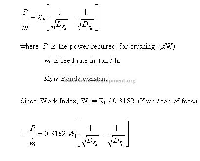
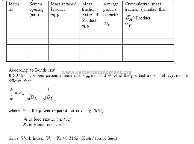
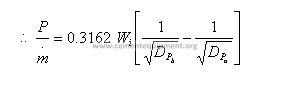
A more realistic way of estimating the power required for crushing and grinding was proposed by Bond. Bond postulated that the work required to form particles of size DP from very large feed is proportional to the square root of the surface-to-volume ratio of the product.
According to Bonds law, if 80 % of the feed passes a mesh size DPa mm and 80 % of the product a mesh of DPb mm, it follows that
REQUIREMENTS
Roll crusher, Sieve Shaker, Sieves, Weighing Balance, Feed.
PROCEDURE
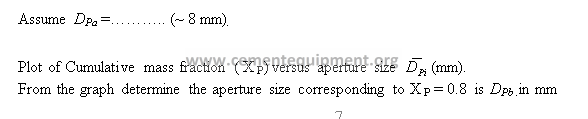
- Prepare 10 Kg feed of laterite stone. The size of the material must not be more than 8 mm (solids passing through GI frame 10 mm and remaining on 4.75 mm ). Note the average size of feed, D
- Switch on the main and MCB (mega circuit board) switch and start the motor.
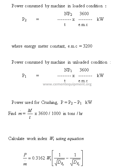
- Introduce feed to the roll crusher, start the stop watch, note the time of crushing (t sec), note the number of pulses (NP2) on the energy meter.
- Run the roll crusher with no load condition for t sec and record the number of pulses on the energy meter (NP1).
- To switch off the machine push the red button and switch off MCB and main.
- Sieve the product for size distribution (using GI frame sieves with aperture size 3mm, 4.75 mm BSS mesh no 6,8, 10,14 and pan).
- Construct a graph of cumulative mass fraction versus aperture size and find out DPb from the graph.
OBSERVATIONS
Feed taken: Laterite sone
Mass of feed taken : 10 kg
DATA ACQUISITION
CALCULATIONS
- i) Calculation of work index Wi
EXPECTED RESULTS
- Plot Cumulative mass fraction (X P) versus aperture size .
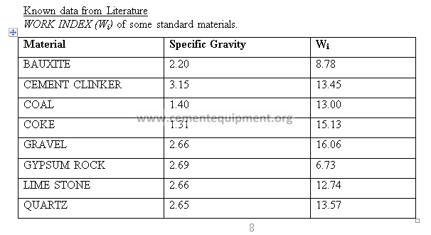
- Determine work index Wi for the material crushed ( in Kwh / ton of feed).
PRECAUTIONS & MAINTENANCE INSTRUCTIONS
- The machine should not run when there is no oil in oil cups.
- All the nuts and bolts of motor and unit fixed with the base are to be checked up before operation.
- Clean the Rolls and whole unit before and after its use with cloth.
TROUBLESHOOTING
If the starter switch is not operating properly and drip as you start it means motor taking over load so remove that.
- Proper cleaning and oiling is necessary.
- If the feed material chokes in between the Rolls stopped the motor and remove the choked material manually.
- If the motor stops during experimentations and as you start but starter drips it means starter over heated stop the crusher for at least 15 min and again start.
REFERENCES
1.McCabe, W. L.; Smith, J. C. and Harriott, P. “ Unit operations of Chemical Engineering”
2.Narayanan, C. M. ; Bhattacharya, B. C. “ Mechanical operations for chemical engineers”.
EXPERIMENT- C BALL MILL
OBJECTIVES
- i) To study the operation of ball mill.
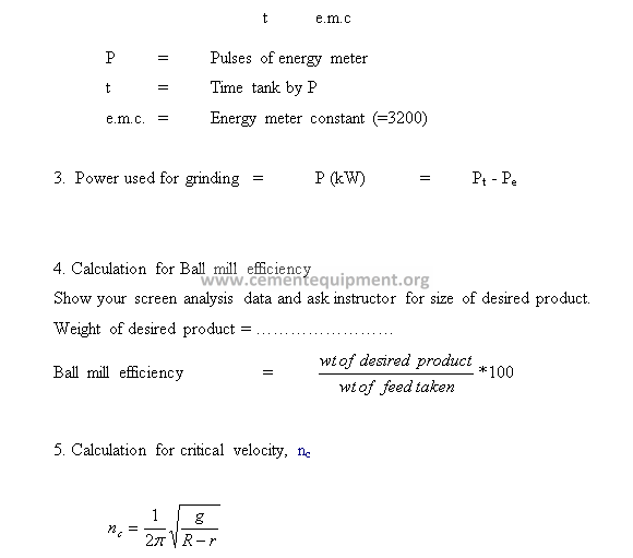
- ii) To determine the efficiency of the ball mill.
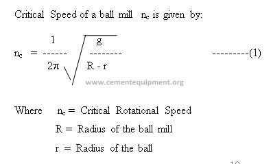
- To determine the critical speed of the ball mill.
THEORY
A Ball Mill consists of a cylindrical shell slowly turning about a horizontal axis and filled to about 1/4th of its volume with solid grinding medium (i.e. metallic balls, wooden balls or rubber balls ). When the Ball Mill is rotated, the grinding elements (balls) are carried to the side of the shell nearly to the top, from where; they fall on the particles under. In a Ball Mill most of the size reduction is done by impact. The energy expended in lifting the grinding units are utilized in reducing the size of the particles. Ball Mill can accept a feed size of 12mm or less and deliver appropriate size in the range of 50mm. The speed of Ball Mill varies between 60 to 70 r.p.m. As the product size become fines, the capacity of a mill reduces the energy requirement increases. The power consumption of a ball mill is in the range of 0.8 to 10 kwh/ton.
For effective operation of the mill, the mill should be operated at 65 to 80 % of critical Speed. As the product size becomes finer, the capacity of a mill reduces and the energy requirement increases. As the speed of the mill exceeds nc (i.e. mill is centrifuging the size reduction capacity decreases.)
The present laboratory Ball Mill is designed to crush particles to very fine (powder) particles. It can handle variety of material. The compact and rugged construction can handle general laboratory or small pilot plant requirements. The shell is fabricated from thick steel and balls are also of special steel. An opening and tightening arrangement is provided in the center of the shell to feed and to take off the material. Balls are provided along with the material.
REQUIREMENTS
Ball mill, Sieve Shaker, Sieves, Weighing Balance, Feed.
PROCEDURE
- Prepare 2 kg feed material to be crushed (8 mm to 6.3 mm size).
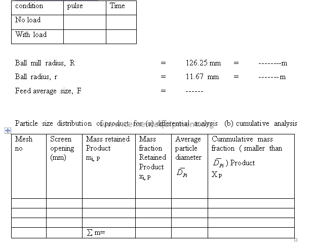
- Note the mill radius, ‘R’ and radius of the balls ‘r’.
- Calculate the critical speed of the mill nc using equation -1.
- Set the operating speed at 0.6 to 0.8 of nc.
- Run the mill without any feed material (only with balls) for a period of time covering 20
Pulses and note the time taken.
- Introduce the weighed feed into the ball mill and close it properly.
- Run the mill with feed and balls for a period of time covering 20 pulses and note the
time taken.
- Stop the main, unlock or disconnect and only then bring the mill to a suitable position, and remove the balls first and then the product is to be emptied.
- Do screen analysis (using screens: 4.75 mm GI sieve, B.S.S 5, 8,14, 25, 72, 100, 150 and 200 and pan) and weigh the mass retained on each screen.
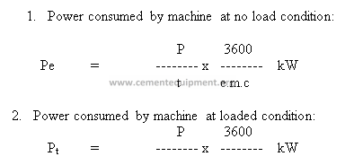
- Calculate the power consumed for crushing only & determine the efficiency of the ball mill
.
OBSERVATIONS
Known data
Shell dia = 275mm (252.5 (ID) + thickness =275 mm
Shell length = 350mm
Maximum size of feed = 12mm
Product discharge siz e = 500mm
Operation on = 220 V, 1 Ph., 50Hz.
Motor = 1 HP, DC
DATA ACQUISITION
CALCULATIONS
- Draw plots for differential and cumulative analysis. Refer to Mc Cabe Smith 6th Ed pg 947, 950.
Differential analysis- Plot of mass fraction vs particle size
Cumulative analysis – Plot of cumulative mass fraction smaller than stated size vs particle size.
EXPECTED RESULTS
- Power consumed ( in kW ) by the ball mill for grinding.
- Determine the critical speed of the ball mill.
- Study the particle size distribution for the product and represent it by differential andvcumulative analysis.
- Study about Bond Ball Mill Grindability test and Bond Ball Mill Work Index.
PRECAUTIONS & MAINTENANCE
- Always use the feed size less than, 5mm and greater than 3mm for ball mill.
- Don’t run the motor below 180 volts and not above than 240 volts.
- Revolution counter should be zero before start.
- Coupling fixing pin should be fixed after attached the ball mill coupling.
- Don’t attach or detached the coupling during the experiment.
TROUBLE SHOOTING
- If the motor is not moving check electric power.
- If power is o k check the motor terminal point if terminal showing the power contact to our company.
REFERENCES
- McCabe, W. L.; Smith, J. C. and Harriott, P. “ Unit operations of Chemical Engineering”
- Narayanan, C. M. ; Bhattacharya, B. C. “ Mechanical operations for chemical engineers”.
- Perry, R. H and Green D,.. Chemical Engineering Handbook.