Contents
Practical Guide about Kiln REFRACTORIES
[wpecpp name=”package + Updates forever” price=”250″ align=”center”]
REFRACTORIES DESCRIPTION
1.1 Manufacturing Processes
1.2 Manufacturing Variations
1.1 Manufacturing Processes
Crushing
Grinding
Screening
Batching
Mixing
Forming step(s) Packaging
Heating step(s) Palletizing
Semi-finishing step(s) Shipping
Finishing step(s)
Palletizing
Shipping
1.2 Manufacturing Variations
Crushing and grinding:
-Coarse crushers:
– jam;
– gyratory and cone;
– dry pan;
– roll crusher;
– hammer mill.
Intermediate pulverizers:
– cage disintegrator;
– hammer mill;
– disk mill;
– autogenous mill.
– Fine grinding mills:
– ball;
– rod;
-roller;
– hammer mill.
Screening (single or multi-decked):
– Stationary screens:
-grizzly
– Dynamic screens:
– inclined vibrating;
– horizontal vibrating;
– oscillating;
-reciprocating;
– sifter;
-centrifugal.
1.2 Manufacturing Variations (cont’d.)
Batching:
-Manual and automatic weighing equipment
Mixing:
– Ribbon
-Muller
-Rotating screw
-Drum-type blender
-Double-cone blender
– Twin-shell blender
-Sigma blade
– Planetary
-Plow
-High-intensity
Forming:
– Hand-molding
– Air-ramming
– Pressing (toggle, friction, hydraulic, wet and dry bag isostatic)
– Casting
– Palletizing
Heating:
– Drying
– Curing
– Tempering
– Baking
– Firing or sintering
– Fusion
1.2 Manufacturing Variations (cont’d.)
Semi-finishing or finishing:
-Impregnating
– Grinding
– Drilling
-Plating
– Banding
– Coating
– Glazing
– Sizing
– Insulating
Packing:
– Bag (paper, plastic)
– Carton
– Supersack
– Can (plastic, metal)
– Drum
– Many thousands of products… and formats
-Many variations between products of the same types
– Classification of refractories next!
SECTION 2
REFRACTORIES CLASSIFICATION
2.1 Basis of ISO Classification
2.2 ISO Coding Systems
2.3 Shaped Basic Refractory Products
2.4 ISO Classification for Unshaped
2.5 Unshaped Refractory Products Installation
2.6 Bonding Mechanisms of Refractory Materials
2.1 Basis of ISO classification
1- Product type
2- Chemical composition
3- Classification temperature
4- Principal raw material
5- State of raw material
6- Nature of bond
7- Post treatment of product
8- Bulk density
9- Shot content
10- Strength
11- Installation method
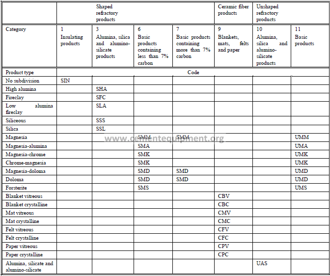
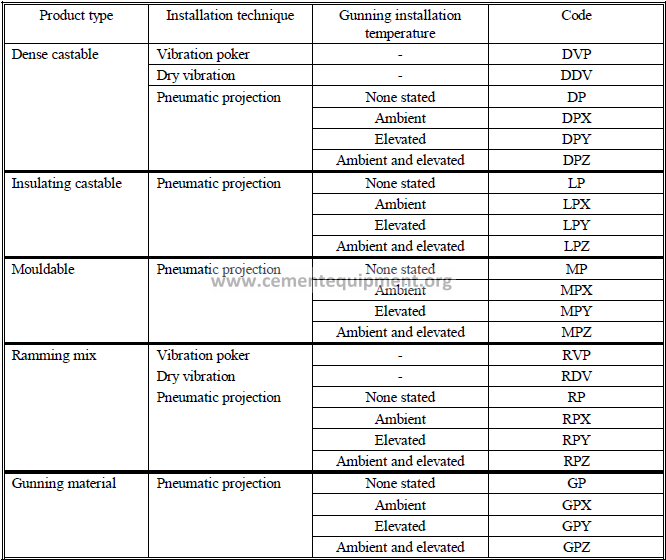
2.2 ISO – CODING SYSTEMS
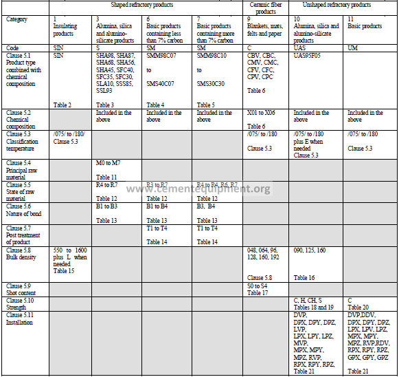
Product Types and Codes
Which includes broad chemical classes and physical appearance
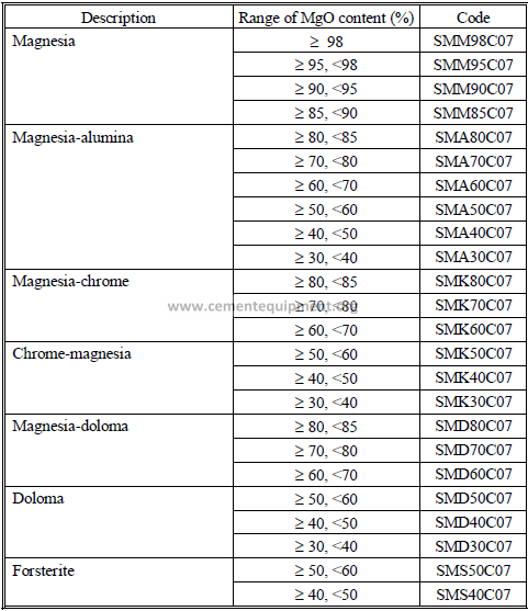
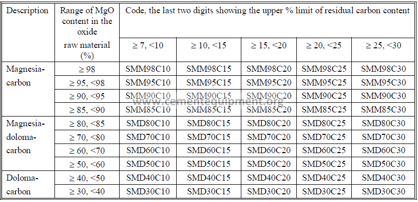
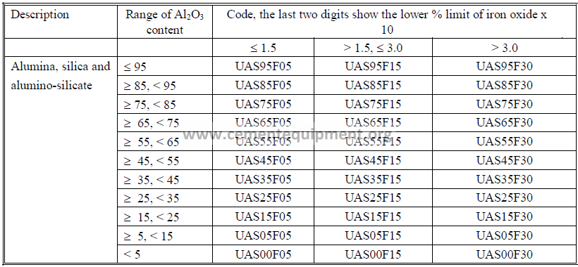
2.3 Shaped Basic Refractory Products
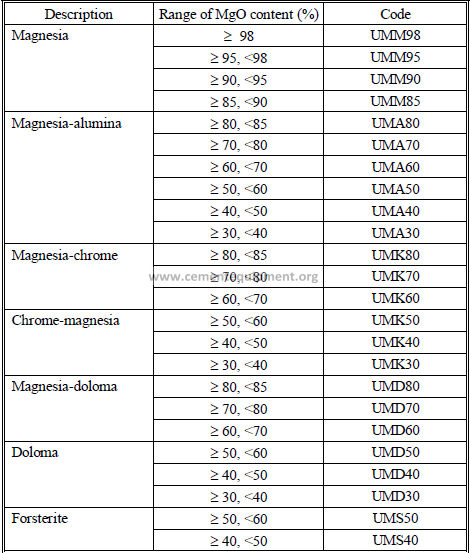
2.4 Part B – ISO Classification For Unshaped
2.5 Unshaped Refractory Products Installation
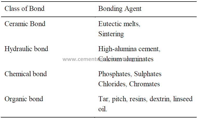
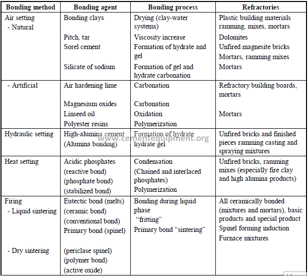
2.6 Bonding Mechanism of Refractory Materials
Introduction
For refractory materials, the cement industry applies the term “bond” to the cohesion occurring in
the natural state because it is of primary interest in subsequent processes. Depending on the firing
temperature, the natural bond will be replaced by a ceramic bond.
If the transition to a ceramic bond occurs without significant loss of strength, the bond is
considered to be “permanent” (example: phosphate bond). In contrast, a pronounced loss of
strength prior to ceramic bonding is called “discontinuous bonding” (example: sulphate bonded
magnesia bricks). The minimum strength remaining in the “intermediate” temperature zone may
drop to 10-20% of the initial strength.
Classification of Bonds According to Bonding Agents :
Refractory Bonding Systems in Brick (B), Mortar (M), Plastics (P), Castables (C)
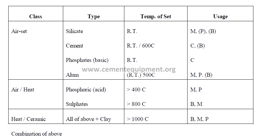
Classification of Bonding According to Hardening Process
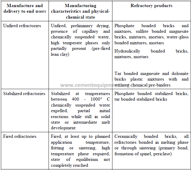
Classification of Bonding According to Manufacturing Process
SECTION 3
REFRACTORIES PROPERTIES
3.1 Properties of Refractorie
3.1 Properties of Refractories
The significant of any refractory – including its high temperature strength – depend on its mineral
makeup and the way these minerals react to high temperatures and furnace environments.
Unfired or green refractories consist of a mixture of refractory particles varying from coarse to
extremely fine sizes. Coarser particles may be 1/4 inch in diameter, and the fines may pass a 200-
mesh screen.
After the refractory has been fired, the fines form the ceramic bond between larger particles. The
fired refractory consists of bonded crystalline mineral particles and glass or smaller crystalline
particles, depending largely on the composition of the refractories.
Most refractories contain a small amount of accessory oxides such as soda, lime, potash and iron
oxide. These “impurities” promote formation of low-melting glasses, and so for many years
considerable research has gone into elimination or control of these accessory oxides in
refractories.
The physical properties of refractories most readily determined are bulk density, porosity and
strength at room temperature.
Bulk density, usually expressed as pounds per cubic foot or grams per cubic centimeter, is an
indirect measure of any refractory’s capacity to store heat. Technically, it is the ratio of weight or
mass to volume.
The porosity of a refractory indicates its ability to resist penetration by slags and fluxes and
permeation by gases as well as influencing its thermal conductivity. Insulating refractories are
lightweights with a porous structure.
The cold crushing strength of refractories indicates ability to withstand handling and shipping
without damage and impact or abrasion in low temperature operations. However, it provides
little or no indication of their strength at furnace operating temperatures.
The most significant properties of refractories are those which enable them to stand up under
conditions found in an operating furnace. Refractories must withstand the maximum service
temperature of the furnace. In most applications the reheat, load and hot modulus tests, should
play an important part in the choice of refractories for high temperature applications. These tests
indicate the strength of refractories in service conditions.
Refractories must often resist spalling effects of rapid temperature changes. They may be called
on to resist heavy loads, abrasion and impact, or the corrosion and erosion caused by liquids and
gases. In general, the refractories that are strongest at operating temperatures show the best
resistance to impact and abrasion.
The standard ASTM Reheat Test, method C113, tests brick for changes in dimensions. In this
test, the bricks are placed in a furnace and gradually heated to a predetermined temperature,
depending on their composition. The test temperature is held five hours and the bricks are
cooled. Then they are measured to determine changes in linear dimensions and volume.
The Load Test, a standard laboratory procedure, measures the ability of a brick to carry a load at
high temperatures, the temperature depending on the quality of the brick. In this test, two 9-inch
straight are set on end in a furnace and a vertical load of 25 pounds per square inch in applied.
Under ASTM Method C16, the temperature is gradually raised and held on a prescribed schedule.
The load test is an accelerated test. In service loads are usually less than 25 psi.
In the Hot Modulus of Rupture Test, refractory samples are brought up to temperature in a
testing furnace. They are placed in the testing machine, supported at both ends across a 7-inch
span and broken in the middle (ASTM C583-76). The machine measures the forace in pounds
required to break the specimen.
Thermal spalling is caused by stresses developed by unequal rates of contraction or expansion in
different parts of the refractory, usually associated with rapid changes in temperature. The brick
with greatest resistance to thermal spalling have the lowest average thermal expansion and do not
expand sharply within any narrow temperature range.
The Panel Spalling Test, applicable to fireclay, some high-alumina and some basic brick, is
designed to measure comparative resistance to thermal spalling. ASTM Method C38 calls for 14
brick laid in a movable panel to form a section about 18 inches square. One side of the panel is
backed by insulation; the other, subjected to heat. After a 24-hour preheat, the panel goes
through a thermal shock treatment, alternately heated and cooled according to a specified pattern.
Results are reported in terms of average percentage loss in weight.
In most furnaces, chemical reaction contributes to the ultimate destruction of refractory linings.
Refractory materials can react with the furnace charge, with slags or other furnace products, with
fuel ash, fumes or dust and in some cases with other refractories. Absorption of liquids or
penetration by gases or fumes into the refractories can change the size and orientation of crystals,
form new minerals or glass and thus alter the physical and chemical characteristics of the
Erosion, washing away grains of refractory after the bond has been destroyed, in a physical
process. Corrosion is the chemical process that destroys the bond.
Dense refractories, low in apparent porosity, generally can be expected to demonstrate greater
resistance to corrosion and erosion. It is a natural assumption and generally true that basic
refractories should be used where basic fluxes come into contact with the furnace lining, and acid
refractories with acid processes. However, there are some exceptions to this general principle due
to differences in operating and reaction temperatures, reaction rates, viscosities of reaction
products and the formation of protective coatings on linings.
Chemical composition represents a guide to the ingredients of the mix. In the fireclay and highalumina
refractories, the alumina-silica ratio roughly indicates the refractoriness of the
composition – the higher the alumina content, the greater the refractoriness. Accessory oxides
also play a part in the quality of the refractory. Lime may be present as a result of the binder in
monolithic refractories.
Iron oxide becomes important in refractory compositions when the process carried out in the
refractory-lined vessel involves a reducing atmosphere. At certain temperatures, carbon
monoxide can react with iron oxide in a refractory causing deposition of carbon within the lining.
If the reaction continues, it will crack the lining. A hydrogen atmosphere will reduce iron oxide,
sometimes producing volatile compounds that can be harmful to a process.
The Pyrometric Cone Equivalent (PCE) provides a standard for evaluating the high temperature
softening behavior of some fireclay refractories.
In this test, a ground sample of the material is molded into test cones and mounted on a ceramic
plaque with a series of standard pyrometric cones. The plaque is heated at a specific rate until the
test cone softens and bends. The number of the standard cone whose tip touches the plaque at the
same time as the tip of the test cone is reported as the PCE value of the test cone.
PCE does not indicate a definite melting or fusion point, but simply offers a comparison of
thermal behavior in terms of standard cones. It is, however, widely used for quality control tests
on fireclay products during mining and manufacturing.
SECTION 4
BRICKS SELECTION
4.1 Refractories Selection
4.2 Selection Criteria
4.3 Guideline in Burning Zones
4.1 Refractories Selection
Materials
-Many suppliers
– Subtile and non-subtile differences
– Installation Methods
-“Know-how” with bricks
– Different with monolithics
– Operating Conditions
-“IPC Concept”
The “Integrated” Approach
(More in Section 7)
A First Example
First Step, zoning, and installation methods (KIV)
Second Step, definition of the constraints
– Causes and effects
– Thermal-mechanical-chemical
Stresses due to… causing such phenomena…
– Definition of the “properties” required
Le cahier des charges par zone
Third Step, variability of the operation
– Key input variables – Key output variables
The IPC… 1 to 4
Fourth Step, correlation-diagnostics
– Post-mortem analysis
Fifth Step, new testing – back to first step
– Analysis – Desk research – Planning – Recording – Synthesis
4.2 Selection Criteria
Thermal factors
-incomplete combustion of fuel, flame characteristics
– variations in dosing of fuel, especially when coal is used, overheating
– displaced, i.e. not adequately oriented, adjusted, burner pipe
– secondary combustion
Chemical factors
– use of fuel rich in sulphur and chlorine
– use of high-ash coal
-frequent change of fuel
– disturbance of the SO3 / (K2O + Na2O) – equilibrium
– high concentration of chlorides (KCI!) in kiln atmosphere (raw meal)
– sulphatizing and/or addition of fluorspar
– variations in cement raw material
-grain size of SiO2 – component
– change between reducing and oxidizing atmosphere
Mechanical factors
– deformation of kilns hell
– ovality, kiln rotation (rpm)
– axial distortion
4.3 Guidelines
SECTION 5
MONOLITHICS
5.1 Monolithics for Preheater
5.2 Monolithics for Kiln
5.3 Monolithics for Burner Pipe
5.4 Monolithics for Hood
5.5 Monolithics for Grate Cooler
5.6 Monolithics for Planetary Cooler
5.1 Preheater
5.1.1 Material Selection
There are many different ways to make a 60% alumina low cement castable, and also different
ways to put it in place. With so many variables at hand, it is not very difficult to make selection
mistakes.
Although easier and faster to install than bricks, monolithic products cannot compete with bricks
in performance. That makes material selection a simple task if longevity is the main factor, use
bricks; if installation time is more important, then choose a monolithic product such as castables
or plastics.
In the upper stages of preheaters, mechanical stability should be the main concern in material
selection. The temperature profile of a modern 6-stage preheater shows maximum gas
temperature of 1620° F for stage 6, and only 545° F for stage 1. Therefore a good quality fireclay
castable is all that is required from stages 3 to 5, a 50 or 60% alumina low cement castable for
stage 6, and a silicon-carbide alumina low cement castable for the flash-calciner, alkali by-pass,
riser duct and feed shelf. The purpose of the silicon-carbide grains is to minimize sulphur and
alkali buildups in the area. For maximum performance, all these linings must be cast-vibrated in
place. Gunning should only be used to install the backup insulation. Suspended roof in the
cyclones and flash-calciner can be lined with refractory plastic rammed in place around brick
anchors.
The most common mistake in choosing materials for preheater application is to put the speed of
installation ahead of material suitability. This difficult decision must be made at a plant level, with
or without the installer’s input. If the preheater lining is supposed to last from 2 to 5 years,
without major repairs, then the installation time should never dictate how the material will be
installed.
Day after day refractory manufacturers develop new products aimed at “speeding up” the
installation. As a consequence, gunning, self-flow, free-flow and pumpables became more
important than alkali-resistant, low permeability, thermal shock resistant products. The results are
mixed and many plants are learning the hard way, by trial and error.
5.1.2 Insulation
Although the total heat loss by radiation in the preheater is less than 2% of the total heat input,
most preheater vessels and ducts are insulated to protect the steel shell.
The use of refractory fiber boards in the hotter sections of the preheater may induce premature
lining failure if the fiber fails behind the dense lining. Fiber boards contain a certain amount of
organic matter that, when exposed to moderate temperatures, burns out with emission of fumes.
The damaged product lacks both mechanical strength and insulating properties, and exposes both
the steel shell and the anchor stem to higher temperatures. The resulting relative movements
damage the anchoring system and induce cracks on the dense lining.
To avoid problems like this, chose an insulating material with the minimum amount of loss on
ignition such as calcium silicate, diatomaceous earth or vermiculite boards, or insulating castables
that can be cast, gunned, sprayed or pumped in place.
5.1.3 Lining Thickness
The ideal lining thickness for any area of the preheater is the minimum thickness required to attain
the specified shell temperature.
If the lining is too thin, the shell and the anchoring system are exposed to temperatures that
accelerate metal corrosion, scaling and fatigue. Once the anchor is “burned out” the lining
collapses. Also the insulating layer may fail at its interface with the dense material, creating gaps
where dust will accumulate and compromise the lining integrity.
If the lining is too thick, high thermal gradients develop within the dense lining, causing it to crack
or spall off. If the insulation is too thick, the dense lining operates at higher-than-normal
temperature and results destroyed by chemical attack or melting. This is particularly true for the
flash calciner equipped with solid fuel burners. Over insulating also brings up the interface
temperature between the two layers, with consequent damage to the anchors and to the insulating
material.
For any type of preheater or precalciner, we recommend a maximum of 5 inches of dense castable
or brick, on top of 4 inches maximum of insulating board, castable or brick. If the combined
lining must be more than 9 in. thick, then use a thicker layer of a less insulating material, and keep
the dense layer constant. A good reason for our success in several installations is exactly the
strict observance of this rule.
5.1.4 Dust Infiltration
This is one of the most common failure modes in preheater applications: red hot kiln dust
infiltrates behind the dense castable or brick and cause one or several of the following damages:
– anchor shearing or breaking
– insulation sintering and shrinking
– lining pushing in from behind
In all three cases the lining in the affected area collapses in a short time. Since kiln dust particles
are in average smaller than 48 microns, they behave like a fluid and find their way through any
open joint, crack or hole in the lining. In cases where the insulation shrinks, dust deposits build
up between the shell and the lining, or between the insulating lining and the dense lining, creating
a tremendous head pressure that, in some instances, pulls the anchor away from the shell.
The best remedy in this type of failure is to air-tighten seal the entire lining at junctions, corners,
ceilings and expansion joints. Metal trays supported by cantilevers or dust traps must be used at
the beginning and at the end of each section. If brick is used, the entire lining must be installed
with a good quality mortar, and brick anchoring must be used to bond the lining from time to
time. Special attention must be given to inspection doors and peepholes. The flanks of the
insulating layer cannot be exposed in those areas. Instead, use the dense material around doors
and holes.
5.1.5 Sulphur Attack
Sulphur penetrates the lining and reacts with the calcium aluminate phases according to:
in operation : SO3 + 2 (CaO.Al2O3) —–> CaO.2Al2O3 + CaSO4
SO3 + CaO.Al2O3 ——> 2Al2O3 + CaSO4
during shutdown: CaSO4 + xH2O —-> CaSO4.xH2O
The formation of anhydrite and gypsum weakens the lining and increases its tendency to promote
and stabilize preheater buildups.
In order to minimize sulphur attack, choose castables with a minimum amount of calcium
aluminate cement (check the CaO content) and increase the lining density. If possible, balance the
sulphur to alkali ratio in the system to decrease the amount of free SOx.
On new linings, apply a protective ceramic coating to seal the open pores and prevent sulphur
penetration.
5.1.6 Potassium Attack
Alumina containing castables, mullite based or bauxite based, are very sensitive to potassium
oxide, chloride, sulphide and sulphate. It reacts with the castable according to:
3Al2O3.2SiO3 + 3K2O —-> 3K2O.Al2O3.2SiO3 + 2 Al2O3
KCl, NaCl + 11 Al2O3 + 1/2 O2 —-> (Na,K)2 Al22O34 + Cl2
During kiln shutdown, the products of reaction undergo a 30% volume expansion inside the
castable, causing an alkali bursting and lining destruction. In the second reaction above, the
product of reaction is a powerful flux that softens the castable in service.
This problem can be minimized using bauxite-based castables, as opposed to mullite-based or
corundum-based materials. Although bauxite also reacts with potassium, the volume expansion is
not as severe as with mullite. Another measure to minimize the problem is to reduce the alumina
content in the product, if the service temperature allows.
Other ways to minimize potassium attack is to decrease the amount of back up insulation and to
seal the finished lining with an alkali-resistant ceramic coating.
5.1.7 Thermal Overload
Thermal overload is becoming a common reason for lining destruction inside the flash-calciner
and at the bottom part of the kiln riser. This trend is a consequence increased synthetic or waste
fuels utilization in the back end of the kiln. Being a process problem, it must be solved at an
operational level.
What causes the thermal overloading are unexpected variations in the heating value of wastederived
fuels. In those cases, the fuel mass input is constant, but not the amount of energy
released during fuel combustion. If this problem cannot be solved by the fuel supplier or by the
kiln operator, then serious consideration should be given to a more refractor, magnesia-spinel
lining.
In some other cases the thermal load is normal but buildups formed in the riser or inside the flashfurnace
direct the hot gases to the wall and destroy it in a short time. The solution is to replace
the lining with an anti-buildup silicon carbide-alumina castable.
5.1.8 Thermal Shock
Lining destruction by thermal shock is becoming more frequent with the trend in waste-fuel
burning in the back end of the kiln. The main source of thermal shock is the frequent opening of
inspection doors to air-blast or worse, water blast buildups formed on the walls. The secondary
source are defective fuel feeding systems that introduce large volumes of cold air in the system in
a cyclic way. Thermal cycling destroys not only the lining but also the anchoring system.
In order to eliminate the need for water-blasting, install a low coatability silicon-carbide alumina
castable in the entire riser and flash calciner sections. In parallel, balance the sulphur to alkali
ratio in the system to help minimize buildup formation. Before the dryout, seal the entire lining
with a rare-earth oxide ceramic coating.
5.2 Kiln
5.2.1 Material Selection
Inside the rotary kiln, three types of monolithic products are used, according to the installation
method: castables, pumpables and plastics. Gunning materials are not recommended inside a kiln
because of their naturally higher porosity and lower strength at kiln temperatures.
Pumpables and self-leveling castables should be limited to the chain section where temperatures
are moderate and the casting volumes are large. When pumping material into the chain section,
especial care must be used in metering the amount of water. Too much water will render the
lining abrasion-sensitive in a zone where abrasion resistance must be maximized.
Plastic refractories have a temperature limitation, caused by the phosphate binder, and require
permanent forming if the kiln is to be turned before heat is applied to the lining. Plastic materials
are mainly used in nose-ring applications, around ceramic anchors.
For other areas of the kiln, low-cement castables roto-cast in place is the best alternative. Usually
a 60% alumina is more than sufficient for the inlet cone, and retaining rings in the calcining zone.
For the nose-ring, a more refractory, higher alumina product can be used, provided there is no
severe alkali attack in the area. In planetary cooler kilns, a 95% corundum low-cement castable is
recommended around the satellite inlets.
No monolithic product should be used at or in the burning zone because of the limited hotstrength
of castables and plastics, and the impossibility to properly anchor the product in place.
5.2.2 Insulation
Back up insulation is not recommended under monolithic products in the kiln. The insulation
lacks compressive strength and could collapse under the dense lining causing its failure.
Moreover, it has a tendency to overheat and destroy the anchoring system. In rotary driers,
roasters and lower temperature kilns, however, back up insulation can be safely used provided the
product modulus of rupture is above 250 p.s.i.
5.2.2 Eutectic Melting
The refractoriness of monolithic products is usually expressed in the manufacturer’s data sheet as
“maximum service temperature”. Following that simple orientation, a 60 or 70% alumina castable
could be used in service temperatures exceeding 3000° F. However, when installed in the rotary
kiln, these products melt at temperatures as low as 1600° F.
Most castables, plastics and gunning materials contain mostly alumina and silica in their
composition, and the minimum melting temperature in the pure system is in fact 3300° F. The
addition of iron, sodium, potassium, calcium, sulphur and magnesium to the system, all elements
present in the clinker melt, drastically reduce the melting temperature of the refractory through
the formation of eutectic combinations. This phenomenon limits the application of monolithic
products to areas of the kiln where clinker melt or salt concentrations do not occur.
5.3 Burner Pipe
5.3.1 Material Selection
The main reason for refractory failure in the burner pipe is differential expansion. Usually most
materials prescribed for burner application are adequate, if they stayed in place.
Material selection for burner pipes must take into account a multiplicity of factors that require
conflicting properties in the material:
– thermal cycling
– alkali attack
– sulphur attack
– high abrasion
– low thermal conductivity
– high refractoriness
Since it is impossible to take all these variables into consideration in the same product, a
compromise solution must be found. Therefore, material selection must be done on a per-case
basis when it comes to burner pipes. A good starting point is the wear mechanism. If we know
what is causing lining destruction then material selection becomes a simple task.
5.3.2 Insulation
Since the main purpose of the lining here is to reduce heat transfer to the metal pipe, a low kfactor
material is a must. Another option is to wrap the metal pipe with insulating felt, to a final
thickness of 1/2 in., and fill the balance with the dense castable.
5.3.3 Lining Thickness
The size of the opening in the kiln door limits the lining thickness on the burner pipe to 1-4 in. A
thicker lining has the advantage of better insulating, but it has the disadvantage of additional
weight on the pipe. A 3 in. lining with 1/2 in. insulation can be advantageously applied to most
cases.
In some kilns the burner lining only wears at the bottom tip, due to high heat radiation from the
clinker and hard sandblasting with clinker fines carried with the secondary air. In this area the
addition of 2% w/w stainless steel needles to the castable will help.
5.3.4 Differential Expansion
This is the main reason for refractory failure on burner pipes. The pipe, the lining and the anchors
are constantly shrinking or growing, sometimes in the same direction, during normal operation,
sometimes in opposite directions during kiln upsets. Therefore it is very important to thoroughly
coat the pipe and all the anchors with a thin layer of any combustible material such as paraffin wax
or bitumen. Upon burning, these materials leave gaps than can accommodate at least part of the
differential expansion. Another way to minimize the consequences of expansion is to use
articulated or floating anchors that allow free castable movements. Any type of rigid anchors
induces stress in the lining and cause it to crack.
5.3.5 Potassium Attack
In certain kilns an alkali cycle is formed between the cooler and the burning zone. Potassium
salts, mostly KCl, K2O and K2SO4 become trapped inside large clinker balls. As these balls enter
the cooler, they burst open under thermal shock and the red-hot core releases potassium vapors
that end up in the burner lining where it reacts with alumina and silica to form feldspars. The
castable becomes weak and as the feldspars crystallize they burst the castable in layers parallel to
the hot face. In order to minimize potassium attack, low porosity, low alumina or no-alumina low
cement castables are recommended. Coating the burner lining with a high temperature ceramic
coating also helps seal the open porosity and deter alkali infiltration. Insulation plays a negative
role by increasing the depth of alkali penetration. Potassium attack is particularly severe in kilns
burning charcoal fines, lignitic fuels or insufflating high-alkali dust in the burning zone. Burning
high moisture fuels also enhances the problem because water increases the vapor pressure of
potassium
5.3.6 Expansion Joints
The burner pipe expands in service and shrinks during kiln shutdown. So does the castable, but to
a lesser extent. Therefore, radial and longitudinal dry joints are installed in most pipes. The
problem with the open joints is clinker dust penetration and subsequent lining destruction. If
joints are truly necessary in a given pipe, care must be taken to build it staggered or shiplapped so
that dust cannot infiltrate. By using articulated or floating anchors and by properly coating the
pipe and the anchors as described earlier, expansion joints can be avoided without any serious
damage to the lining.
5.3.7 Clinker Blasting
The burner tip is constantly blasted by the secondary air stream. At burning zone temperatures,
most castables lose strength and result severely abraded by the impinging particles. In planetary
cooler kilns the same happens in the mid-section of the pipe. The best way to solve this problem
is to zone the lining, using an extremely abrasion resistant material in these specific areas. Silicon
carbide or corundum low cement castables are the most suitable products for the application.
5.3.8 Clinker Impact
In grate cooler kilns, when the burner pipe is positioned inside the kiln, past the nose ring, large
lumps of clinker and coating constantly fall on the upper half of the pipe, damaging the lining by
impact. To solve this problem, a v-shaped piece of Inconel can be welded to the pipe, forming a
roof that will divert the falling pieces away from the castable underneath. The same applies to
burner pipes in satellite cooler kilns at the satellite ;inlets. The best solution here is to create a
tray on the upper side of the burner, exactly in the area where the clinker impacts. This metal tray
or box is then filled with loose clinker nodules that can absorb the impact. The box is built over
the regular lining.
5.4 Hood
5.4.1 Material Selection
For lining purposes the kiln hood must be divided in at least two areas: the upper half, towards
the burner pipe, and the lower half towards the cooler. The upper half side walls and ceiling work
under high temperature and high heat radiation. It is often subject to thermal spalling during
clinker and coating avalanches, or during temporary kiln shutdowns when the hood door is open.
The lining in this area is constantly exposed to alkali and sulphur coming from the cooler with the
secondary air. These conditions are getting worse with the advent of the high-efficiency coolers
that elevate the secondary air temperature a couple hundred degrees. The best lining in those
circumstances is a 50 or 60% alumina, low cement castable. If the secondary air temperature is
above 1650° F and loaded with potassium, then the best alternative is to line the hood with
MAGKOK bricks backed up by insulating fire brick or calcium silicate board.
The lower half of the hood can be advantageously lined with a non-wetting silicon-carbide
alumina or zircon-alumina low cement castable. Non-wetting properties are desired to minimize
showman formation in the cooler.
Independently of which material is used in the application, pre-cast, pre-fired modular blocks
should always be preferred to cast or gunned in place materials.
5.4.2 Insulation
The kiln hood must always be insulated due to the high heat concentration in the area. As the
work lining thins down by wear, the insulation keeps the shell from overheating and warping.
Moreover, there are always people circulating around the hood and a hot shell poses a safety
problem to the workers and visitors.
The integrity of the insulation is critical to the work lining integrity. If hot clinker dust penetrates
the insulating layer behind the dense castable or brick, it quickly damages the anchoring system
and pushes the lining away from the shell until it collapses. Most insulating materials shrink at
hood temperatures and make the situation even worse.
When choosing an insulating material for hood application, make sure it contains no organic
binders, its limit service temperature is above 2000° F and it retains its full integrity at that
temperature.
Our recommended choices are 2000 degrees calcium silicate boards or 2300 degrees insulating
castable gunned in place.
5.4.3 Lining Thickness
The lining thickness is a function of the hood design and the desired temperature on the hood
shell. It is always better to have a highly abrasion-resistant lining in a thin layer, than a
conventional material in a thick layer.
The dense lining in the hood is usually a medium to high alumina castable or plastic. For such
materials the dense layer should not be thicker than 8 in., and the backup insulation should not be
thicker than 3 in. If the insulation is too efficient, the dense, work lining can be severely infiltrated
and destroyed by alkali attack. Thicker linings also are subject to higher thermal gradients and,
consequently, more prone to crack.
If lining the hood walls with RefrAmerica’s modular blocks, the dense layer will be 7 in. thick, and
the insulation will be 2 in. thick.
5.4.4 Potassium Attack
In certain kilns an alkali cycle is formed between the cooler and the burning zone. Potassium
salts, mostly KCl, K2O and K2SO4 become trapped inside large clinker balls. As these balls enter
the cooler, they burst open under thermal shock and the red-hot core releases potassium vapors
that end up in the burner lining where it reacts with alumina and silica to form feldspars. The
castable becomes weak and as the feldspar crystallize they burst the castable in layers parallel to
the hot face. In order to minimize potassium attack, low porosity, low alumina or no-alumina low
cement castables are recommended. Coating the burner lining with a high temperature ceramic
coating also helps seal the open and deter alkali infiltration. Insulation plays a negative role by
increasing the depth of alkali penetration. Potassium attack is particularly severe in kilns burning
charcoal fines, lignitic fuels or insufflating high-alkali dust in the burning zone. Burning high
moisture fuels also enhances the problem because water increases the vapor pressure of
potassium.
5.4.5 Sulphur Attack
Sulphur penetrates the lining and reacts with the calcium aluminate phases according to:
in operation: SO3 + 2 (CaO.Al2O3) —-> CaO.2Al2O3 + CaSO4
SO3 + CaO.Al2O3 —-> 2Al2O3 + CaSO4
during shutdown: CaSO4 + xH2O —-> CaSO4.xH2O
The formation of anhydrite and gypsum weakens the lining and increases its tendency to promote
and stabilize preheater buildups.
In order to minimize sulphur attack, choose castables with a minimum amount of calcium
aluminate cement (check the CaO content) and increase the lining density. If possible, balance the
sulphur to alkali ratio in the system to decrease the amount of free SOx.
On new linings, apply a protective ceramic coating to seal the open pores and prevent sulphur
penetration.
5.5 Hood
5.5.1 Material Selection – Side Walls
Gunnables, pumpables, self-flow, self-leveling and shot-crete materials follow the FIFO RULE in
this application: Fast-In-Fast-Out. Since we want the cooler lining to last at least three years,
with minor repairs, the installation velocity should never dictate which materials will be employed.
The best alternative to line cooler walls is still brick, but, unfortunately, this technology is dead in
the U.S. The acceptable options left are conventional or low cement castables cast-vibrated
behind forms and held in place by a combination of metal and ceramic anchors. A 60% alumina
product is sufficient for most applications.
Another interesting alternative, finding more and more acceptance in cement plants, is the
modular lining which offers the advantages of both bricks and castables. In this alternative the
castable is pre-cast and pre-fired into blocks that have the insulation and the anchoring system pre
attached
5.5.2 Material Selection – Roof
The cooler roof lining works under high heat radiation, thermal cycling, tensile stress, gouging
abrasion from clinker fines and a constant risk of dust collecting behind the lining.
High alumina plastic held by a combination of ceramic and metal anchors is recommended, but it
requires a perfect dryout before the kiln starts. A second option is a low cement gunning mix,
gunned over a lightweight material also gunned in place.
5.5.3 Material Selection – Back Wall
The main wear mechanism in the back wall is heavy impact from hot clinker balls bouncing from
the bed of material. A corundum or silicon carbide low cement castable can be advantageously
used in the area of impact.
Another common problem in modern coolers, with high secondary air temperature, is the
formation of snowman that raise to the kiln level. The use of a non-wetting silicon carbidealumina,
silicon carbide or alumina-zirconia low cement castable should address the problem.
These materials are available in modular blocks for prompt installation.
5.6 Planetary Cooler
5.6.1 Material Selection – Inlet and Elbow
Mechanical stress, clinker abrasion, clinker impact, high temperature and varying temperature are
the main factors in this area of the kiln. Mullite based or corundum based, coarse grained low
cement castables should be used in this application, with or without 2% w/w steel reinforcement.
The anchoring design and the expansion joints design are critical for good material performance.
5.6.2 Material Selection – Tubes
Abrasion and impact are the main wear factors here. The cam lining should preferably be in
mullite brick, and base lining in fireclay brick or low cement castable.
6 REFRACTORIES INSTALLATION IN A ROTARY KILN
6.1 Introduction
6.2 We must look at general requirements when we start a new
installation or a repair job
6.3 Different methods of installation in a rotary kiln
6.4 Kiln cleaning (kiln coating removal)
6.5 Drilling (thickness of the brick lining)
6.6 What refractory should be stripped
6.7 Installation of the individual brick grade (zoning suitable for the
different burning process)
6.8 Installation
6.9 Nose-ring
6.10 Installation methods for castable
6.0 METHODS OF REFRACTORY INSTALLATION IN A ROTARY KILN.
6.1 Introduction
-The lifetime of the refractory lining in rotary kiln is base on different conditions:
– The operating conditions of the plant
-The condition of the kiln shell ovality in the tyre area and the procedure of
heating-up and cooling down the kiln
– The choice of refractory materials in respect of its quality and its positioning
(zoning) in the kiln
-A proper and efficient installation of the refractory lining will not only help to
increase lifetime and eliminate some stresses. It will prevent premature wear.
6.2 We must look at general requirements when we start a new installation or a repair job
– Safety for workers (they have to be well instructed and we must give them the
appropriate tools).
-Installation quality. The lining must be installed in such a way that it will fit the most
perfectly and tightly against the kiln shell that will increase lifetime to the refractory.
– Acceptable bricking progress. A good planning, a good supervision and appropriate
tools will help to reach this goal
6.3 Different methods of installation in a rotary kiln
The following methods will be demonstrated in the Baker brick installation video
– Screw Jack method
-Glueing method
– Hydraulic and pneumatic method
6.3.1 Screw Jack Method
Advantages
– Low investment in equipments
– Possibility to rotate the kiln during the job
Disadvantages
– A slow method of installation
– Necessitate to turn the kiln very often (slow down the job)
– Can be used only in small kiln, not more than 4.5 Ø
– It is not a very safe method for the workers
6.3.2 Glueing Method
Advantages
– Kiln can be rotate at all time during the lining work
– Low investment in equipment
– Easy access to the lining work (no scalfoling or platform required)
– Fast method of installation
Disadvantages
– Storability and used (critical temperature has to be respected)
– Requires to turn the kiln very often
– When gluening bricks over welding seams, corrections can not be made with
mortar on the extrado side of the bricks
– That method is not save for the working personnel. The shell must be very
clean and free of rust and specified temperature has to be respected. That is
why this method is only use on specific job for example in very narrow area.
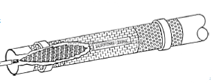
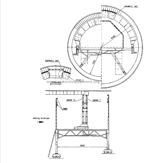
6.3.3 Hydraulic and Pneumatic Jig (mul-o-ring method)
Advantages of this method
– The rig can be moved easily along the kiln, so that there is no need for the
platform to be continually rebuilt compare to some other method
– The kiln does not have to be rotated. There is no time lost to modify access
paths and electrical wiring, etc.
– This method is reliable and safe.
– The bricking progress is very good, 6 to 8 hours per tonnes of bricks install.
It is about half the time of the other method.
Disadvantages of that method
– With this method, the possible kiln turns have to be scheduled many hours in
advance, so that enough time is allowed to close all the open rings.
– It is more difficult to install bricks with mortar in the upper section of the kiln.
The equipment get dirty and it may cause malfunction of the cylinders.
– High investment costs for equipments.
– When lining a long section, all keys are in the same area. It may cause a
weakness in that area.
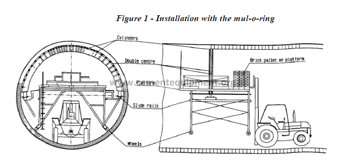
Figure 2 – Mul-o-ring
6.4 Kiln Cleaning (kiln coating removal)
Kiln with diameter Ø bigger than 4.0 m has to be free of his coating and clean.
Completely from the nose-ring to the inlet.
– To protect the workers from the falling coating
– To permit a good inspection of the bricks lining
Kiln with smaller Ø don’t loose easily its coating, thus it is possible to leave the coating in
place, as long you are sure of the good condition of the bricks lining.
6.5 Drilling (thickness of the brick lining)
Make drilling at 3 points equally distribute on the kiln circumference and at every meter
along the kiln. Keep these informations as records for the follow-up of the lining refractory.
You will need these informations to decide witch sections of bricks lining should be stripped
and also for the planification of the next shut-down.
6.6 What refractory should be stripped
Each plant has to establish its own criteria in regard of their past experience taking in
consideration their constraints.
Most plants consider that a lining thickness of 125 mm in the sintering zone is acceptable for
a regular campaign (normally for 1 year).
In case of a very difficult lining section, like transition zones, the use of a brick consumption
factor may be very useful.
6.6.1 Defining a brick consumption factor
For a specific linear meter of brick in the kiln, calculate the factor which consist of the
grams of brick consumed per ton of clinker produced
Make a relationship between that factor and the thickness of the bricks left.
Use that figure to find out the thickness of bricks lining you will normally need for
your next campaign for that specific section of lining.
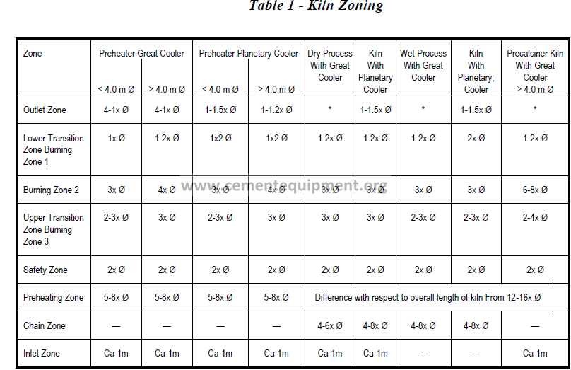
6.7 Installation of the individual brick grade (zoning suitable for the different burning
process)
The choice of the brick grade must be suitable for the individual zone in different burning
process (wet, semi-dry, dry, preheater and calciner). The brick grade should be selected to
meet the special requirements of each individual rotary kiln.
6.8 Installation
6.8.1 The following are to be followed when installing the brick
a) No change of material in the tyre area
A change of material in the tyre area, from magnesie-chromite or magnesia-spinel
bricks to alumina bricks should be avoided, as due to different thermel conductivity
and coating behaviour of different refractory bricks installed on both side of the tyre.
That will cause differential tyre clearances. The tyre will not run on the whole
surface, resulting in increased ovality and higher stresses to the refractory lining, thus
resulting in damages to the refractory of that zone.
The same applies to the change from alumina to MgO bricks.
b) No use of different MgO brick grade in the burning zone
If small parts, of magnesia-chromite bricks are installed in the coating-free transition
zone between high-alumina and magnesite-spinel bricks, the magnesia-chromite bricks
are exposed to high mechanical load due to their different refractoriness under load as
a consequence there is often caused a premature wear of the refractory lining.
6.8.2 Installation with mortar, clench-laid or metal shims
a) Installation with mortar
Advantages
– Refractory bricks installed with mortar form a gas-tight monolithic unit. Any
mechanical loads occurring due to kiln shell ovality, are distributed more
uniformly over the entire lining, so that brick hot face spalling is rare.
– Differences in brick dimensions can be compensated for, by means of mortar,
so that it is easier to follow the mixed lining ratio.
b) The following points must always be observed
The mortar must be mixed in accordance with the manufacturer’s instructions. There
is three basic types of mortar available for rotary kilns:
– High-alumina mortar
– Magnesia mortar
– Fireclay mortar
It is recommended to use the product pure undiluted to avoid premature setting.
– The mortar should be spread uniformly to give a maximum joint thickness of 1 to
1.5 mm.
– No mortar is applied to the kiln shell or the extrado side of the bricks.
c) Clench lining (V.D.Z. ISO)
The method is coming more and more adopted in recent years. The following details
should be noted.
– It is recommended to depart from the theoretical mixed brickwork and to adapt
the mixed brickwork to the kiln shell requirements.
– The extrado side of the bricks must be completely in contact with the kiln shell
and the horizontal joint must point in the direction of the kiln axis.
– For this purpose, it is necessary to adapt the mixed brickwork to the kiln shell
requirements.
– Sometimes the brickwork become stepped, particularly near the welding seams.
To compensate for this, thin mortar joints may be applied between the bricks and,
in the case of larger welding seams beneath the bricks. In no case any metal shims
should be used as to compensate for this.
– In the case of a kiln with large ovality and big shell deformation, it will be wise to
use mortar.
d) Installation with metal shims
– Some of the magnesia bricks, are still laid with metal shims. From our
experience, these shims get oxidized during the operation, take volume
specifically on the hot face and cause premature wear to the refractory lining.
– Like the other method, the bricks must be completely in contact with the kiln shell
and the horizontal joint must point in the direction of the kiln axis.
– When closing the rings, avoid by all means the insertion of two metal shims into
one brick joint
6.8.3 Expansion joints in brickwork
– Because of the different thermal expansion behaviour of refractory materials, the
increased expansion in the case of magnesia bricks must be compensated for, by
the insertion of cardboard spacers.
– Alumina bricks do not need any additional joints, since the expansion of this
material is slightly greater than the expansion of the entire rotary kiln axially and
vertically.
– With basic brick grades, expansion joints of 2 mm are inserted between the
individual ring (2 mm is the equivalent of 1% of the brick length).
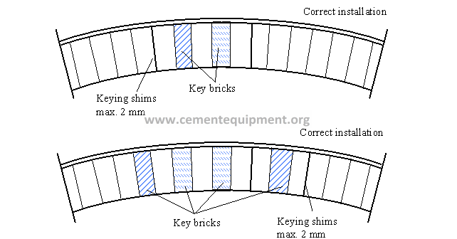
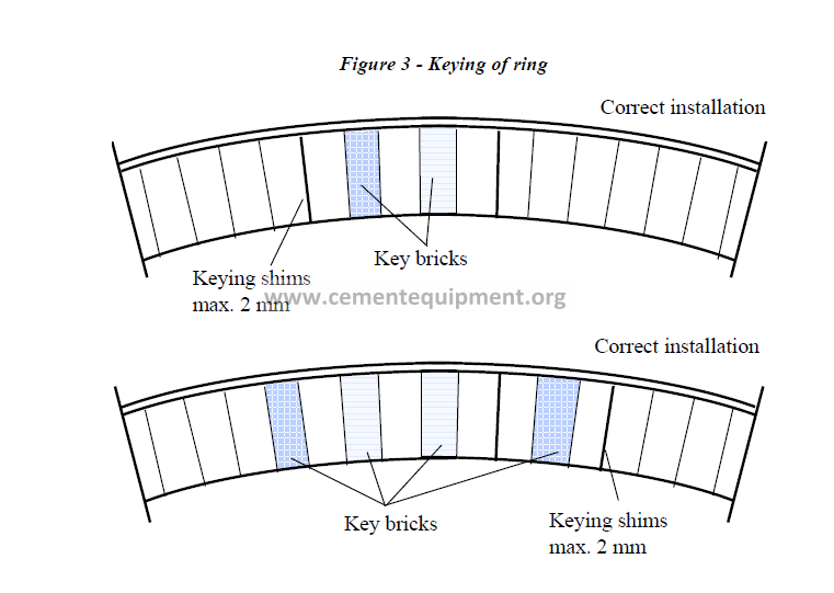
6.8.4 Ring Closure
Correct closure of the brick ring is very important to secure the brick work (Figure
3).
– Use only the original brick to close the rings. Never use cut bricks to fit the
closure.
– Never use key bricks side by side, alternate them with standard VDZ or ISO
shapes. Same with ASTM.
– The metal shims used for the closure, should have a thickness of not more than 2
mm.
– Never use more than one metal shim per joint. If more than one shim is needed
for keying the closure bricks, they should be distributed over the entire closure
area.
– Sharpening of metal shims makes insertion much easier.
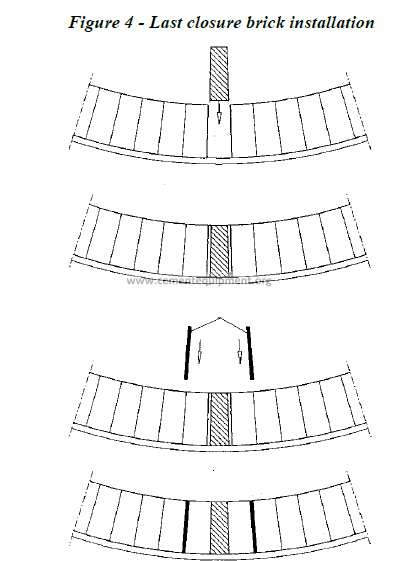
a) Installation of the last closure brick
The final brick of the ring must be inserted from above because it is impossible from
the side as in the case of other rings (Figure 4).
– Make sure that the last bricks are tightly pressed against kiln shell and that the
horizontal joint extends in the direction of and parallel to the kiln axis.
– Make the opening for the last brick such that a standard VDZ or ISO shape brick
fits. Do not use any cut bricks. Same for ASTM. The ring is secured by
knocking in keying shims which should be distributed over the entire closure
zone.
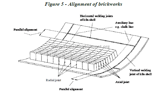
6.8.5 Important points to take care of during the bricking work
One of the important thing for a good lining lifetime is the installation of the
refractory bricks in separate ring without any entangle of the ring to one another.
This can be achieved if the ring are place exactly parallel to the vertical seams (Figure
5).
– Reference lines are drawn on the kiln shell parallel to the welding seams at every
1.5 m. These lines must be strictly followed for the lining work.
– If only a section of the lining refractory has to be repaired, take the nearest
welding seam as a reference line. An uncut ring should be laid to secure the older
lining. Cut the following ring of new brick to adapted with the new alignment.
– The last ring have to be adapted to the old lining. You need to have at least 100
mm brick length to join the old lining. If impossible, cut the two last consecutive
rings. By doing so, this shall respect the minimum length of brick recommended
(some companies provide bricks 250 mm, that avoid to cut on two rings of
bricks).
– As a guideline for the brickwork, the long axis of the kiln is to be determined.
Two point needs to be located. The lowest point in the kiln is determined at the
start of the section to be lined, using a spirit level parallel to a vertical welding
seam. The same is done at the end of the section to be lined. These two points
are then connected by a line. A timber batten or steel angle is placed along this
line and fixed to prevent it from shifting. This gives a straight brickwork end,
which subsequently facilitates closing of the ring.
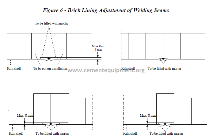
a) Brick lining over welding seams
– A welding seam higher than 8 mm the bricks should be cut to fit the shell (Figure
6).
– A welding seam lower than 8 mm the bricks are backed with mortar. So the brick
can be installed parallel to the other brick rings.
– With the glueing method, the brick have to be cut out above the welding seams.
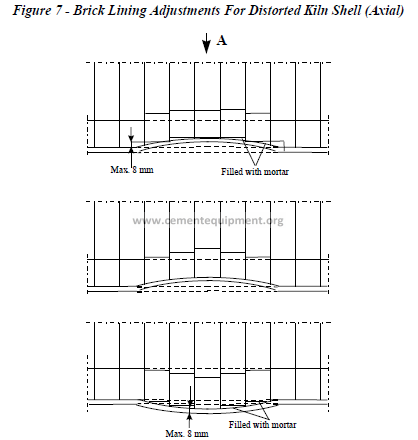
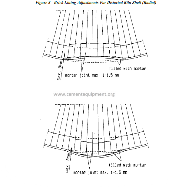
6.8.6 Installation of bricks lining over distorted kiln shell is possible but it has to be
done very carefully
– Like usual, the extrado side of the brick must fit tightly against the kiln shell
(Figure 7).
– The horizontal joints must be laid with mortar. The maximum mortar joint
thickness between the bricks should not exceed 1.5 mm.
– Mortar is use to compensate for irregularities between the extrado side of the
bricks and the kiln shell. Maximum thickness 8mm.
– It is advisable to position these deformed kiln area in the lower half of the kiln
before starting bricking.
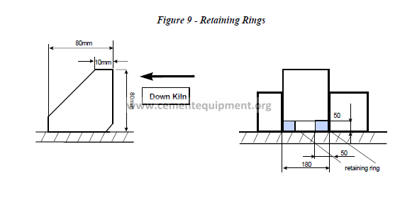
6.8.7 Retaining rings
– Because of the kiln’s inclination of 2.5 to 4% and refractory expansion, a pressure
is done towards the kiln outlet. A way to compensate this is the use of retaining
rings in several places in the kiln. Usually, the retaining ring is installed at every
35metres apart. Never install a retaining ring in the burning zone, the transition
zone , over the tire or the kiln drive. In these zones, the basic brick expansion
(1.6 to 1.8% and mechanical stress causes high pressure against retaining rings
resulting in damaged brick. Thus leading to hot spots.
6.8.8 Types of retaining rings
We have found that a successful retaining ring is made of a pair of rings separated by
80 mm. Each ring from the pair has a square section of 50 mm by 50mm and is made
from 8 to 10 segments depending on the kiln size diameter. The retaining ring is
designed such that a brick of 198 mm can be laid on top of them. The other type of
recommended retaining ring is the triangle shape one as shown below. Like the
other one, it is made from 8 to 10 segments. The lower retaining ring should be place
at least 800 mm up-hill of the nose-ring.
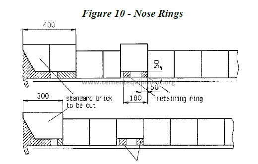
6.9 Nose-ring
The most two types of lining used for nose-ring construction: bricks or castable.
6.9.1 Bricks construction
Quality of bricks required:
-High abrasion resistance
– Good thermal shock resistance
– Good resistance to mechanical stresses
-Good resistance to alkalies
a) Advantages
– Easier and faster to install
– Heating up procedure much faster than the castable lining
– Can be installed without regard of temperature
– Quality of the lining remain constant all around the brickwork
– Easier to replace compare to castable
Some nose-rings are builted with special bricks shapes. Other are builted with bricks
cut from standard shapes. The manufacturers can not produce special shape bricks
that correspond to the required quality, because of the complicated production
technic. The experience has proved that the use of regular bricks shape has done
better results.
6.9.2 Castable lining nose-ring
a) Advantages
– Easier to install over distorted kiln shell
– A solution in case of bricks shape breakdown
6.10 Installation Methods For Castable
6.10.1 Installation Temperature
Installing castables at sub-zero temperatures requires pre-heating of the job site internally and
externally, pre-heating of the water and of the monolithic materials to at least 60° F. Failure to do
so may cause the following problems:
– poor material densification
– incomplete hydration of the binder yielding a product without strength
– no setting or delayed setting
– formation of heat-sensitive phases that cause stream explosion during heatup
The risk of explosion increases with the amount of water required for casting, and with the lining
thickness. Insulating castables present the additional risk of being trapped between the steel shell
and the dense lining.
Plastic refractories are also sensitive to sub-zero temperatures. The hardening reaction between
the phosphate phase and alumina requires a minimum initial temperature to start. If the reaction
only takes place during the kiln heatup, the lining may result severely damaged or even collapse
upon form removal.
Installation at temperatures above 100° F also present risks to material performance. Similar to
what happens at sub-zero temperatures, poly-hydrated calcium aluminate phases may form.
During heat-up severe steam explosions may occur when large volumes of chemically bonded
water is released at moderate to high temperatures. Another risk is rapid waer evaporation before
the binder is fully hydrated, during the curing period. An underhydrated castable will be weak and
easily destroyed by chemical attack. The remedy in such cases is to keep the bags and the mixing
water in a cool place before the installation starts, and to cure the cast lining under a membrane or
moisture saturated air.
6.10.2 Amount of Water
Every product in the market requires a specific amount of water for proper installation and
strength development. Low cement and ultra-low cement castables are particularly sensitive to
the amount of water used during the grain porosity and the quantity of cement used in the product
formulation.
The symptoms of too much water are quite evident:
– no abrasion resistance
– smooth surface finish, without voids or open pores
– visible wood-grain pattern from the plywood forms
– sensitivity to thermal shocks
– unreacted, dry dust inside the pores
– reduced bulk density
– considerably reduced modulus of rupture
The solution to this problem is simple: control the amount of water added to the mixer to the
nearest hundredth of one percent. If the installation is done by gunning, then control the amount
of pre-mixing water and the amount of water added to the nozzle.
Rarely a castable fails for lack of water, and the reason is understandable: it is very difficult to
install a “dry” castable.
The same concepts applied to moisture, also apply to the binder in chemically bonded products.
Binders are usually phosphoric acid or phosphate salts dissolved in water. Too much binder
generates excess heat that may induce expansion cracks in the lining, besides impairing material
workability during vibration. It also promotes grain segregation and further material spalling.
Insufficient binder or weak binder solutions lead to unacceptably long setting time, or no setting
at all.
6.10.3 Water Quality
The best advice here is: if you cannot drink it, do not use it. Brackish waters, with high
concentrations of dissolved salts or organic matter cause serious setting problems, besides
introducing fluxes into the castable. This is particularly true for low-, ultra low- and no-cement
castables with reduced amounts of calcium aluminate cement, in high temperature applications:
flash-calciner, riser duct, hood, back wall in the cooler, nosering, bullnose and burner pipe.
6.10.4 Curing
After the product is mixed with waer or liquid binders, a considerable amount of time is required
for full strength development. The strength comes from chemical reactions and new-phase
formation in the product. Failure to observe the curing time leads to premature material wear by
disintegration, abrasion, thermal shock or chemical attack. No matter how quick the installation
is performed, the curing time cannot be changed. For most castables the binder is calcium
aluminate cement that requires a minimum of 12 hours for complete hydratation. Plastics and
some no-cement castables can be cured in shorter times without any problem. Material hardening
or setting must not be confused with material curing. Hardening occurs in a few hours or minutes
after mixing, whereas curing requires a minimum of 6 hours. Beware of “magic” products that
can be “cast and fired in minutes”. This is only possible with hot-gunning materials used in the
steel industry, but the binding mechanism for those products is totally different from castables.
6.10.5 Dryout
Problems with product dryout are easy to identify because they usually occur in an explosive way,
exposing lives, lining and equipment to serious risk.
Monolithic products made with hydraulic binders contain three different types of water:
chemically combined, absorbed and adsorbed.
Adsorbed or free water is released at room temperature, through normal evaporation. It rarely
presents any problem if it leaves the castable.
Absorbed water is retained inside mini-pores and crevices of the refractory grains. The porous
grains act like a sponge. Since the water is retained by capillary forces, it requires more energy
(and time) to be released than free waer, and could cause material cracking or fracturing if the
temperature raise is too abrupt.
Chemically combined water, a product of hydration reactions, is chemically bonded into the
structure of the compounds, and requires high amounts of bonded into the structure of the
compounds, and requires high amounts of energy to be released. The quantity of chemically
combined water varies with the amount of hydraulic binder and the curing temperature, as
previously discussed. If the material is installed outside the recommended temperature range, the
amount of chemically combined water can increase to large proportions, relative to the total
amount of water. During dryout, the chemically combined waer is released at temperatures above
500° F, when the castable surface is already at a much higher temperature. That generates
tremendous volumes of stream in a short period of time. If the dryout is not slowed down at that
moment, the internal pressure will blow the castable out with complete destruction of lining. The
best remedy to avoid such accidents is to contract the dryout from a specialized company. Their
burners are capable of releasing large volumes of moderate temperature gases and vapor that
promote steady steam release at critical temperatures, without creating considerable thermal
gradients in the lining. The price charged for a professional dryout more than compensates for the
cost of an accident. More and more plants are moving in that direction.
6.10.6 Anchor Material
No castabe will be stronger than the anchor that holds it in place. Experience has shown that
most castable failures are attributable to anchor failure.
Based solely on metal scaling resistance:
up to 1550° F ASI 304
up to 1850° F ASI 309
up to 1900° F ASI 310
up to 2000° F ASI 330
up to 2000° F INCONEL or, preferably, CERAMIC ANCHORS
The problem with temperature tables is their failure to address the fatigue properties, structural
transformations and load bearing capacity of metals at kiln temperatures. Tensile, elongation and
flexural strength must also be taken into account when selecting an anchor material.
AISI 300-series stainless steels, when held between 800-1500° F for long periods of time,
undergo a structural change called carbide precipitation. As a may fail in service in a short time.
Carbide precipitation also renders the anchor stem or tips extremely brittle.
Inconel is not a steel. Inconel represents a family of several Nickel super alloys used in turbine
and furnace parts exposed to extremely corrosive environments. It should be used in applications
where the lining thickness is reduced and the service temperature is relatively high: hose-ring,
bullnose and burner pipe. Like for any other metal, its limit of rupture drops sharply with
temperature:
INCONEL 601 INCONEL 700
1200° F for 1,000 hours 57,000 psi 86,000 psi
1500° F for 1,000 hours 24,000 psi 32,000 psi
1800° F for 1,000 hours 17,000 psi 3,500 psi
Whenever possible, ceramic anchors should be used because of their many advantages over metal
anchors:
– higher refractoriness
– no scaling
– no elongation
– higher hot strength
– lower thermal expansion
– higher holding capacity
– higher load-bearing properties
– not sensitive to welding
When selecting ceramic anchors attention must be given to material behavior towards chemical
attack and thermal cycling.
6.10.7 Anchor Dimensioning
When it comes to metal anchors, there are two different schools of thought: those who prefer
many thinner anchors, and those who prefer a few thicker anchors. Since anchor failures occur in
both cases, the problem with anchor dimensioning must be somewhere else.
For a given anchor spacing, the anchor dimension is a function of the load it will bear (lining
thickness and position), the scaling resistance of the metal and the working temperature which in
turn affects the mechanical properties of the metal. Of particular interest are the tensile strength
and the flexural strength.
Common sense dictates that less metal is needed in floor positions, more metal is needed in walls
and a lot more in suspended roofs. It also tells us that more metal is required in hotter areas than
in colder areas.
The problem with too many anchors or with massive anchors is the expansion damage they can
cause. Since the expansion problem can be easily addressed, more metal should be the way to go,
especially in highly corrosive environments. Too many thinner anchors have the disadvantage of
offering too much surface for corrosion and scaling, and making lining removal for repairs very
difficult. None of these difficulties exist with ceramic anchors.
Another important point in anchor dimensioning is the anchor height. Ceramic anchors are always
flush with the dense lining, whereas metallic anchors are always embedded in the lining. Here,
again, there are two lines of thought: some people try to keep the metal anchor as far away from
the hot face as possible, to protect it from heat. Others prefer to expose the anchor tips to direct
heat contact, claiming that it holds the material better and the anchor wears out with the castable.
Common sense tells us that if the anchor is to hold the castable in place, then the 2/3 or 3/4 rule is
wrong: 1/3 to 1/4 of the lining is not anchored.
The most common mistake is to bury the anchor in the castable, 25% to 33% far from the hot
face, without allowing for longitudinal, lateral and diametral thermal expansion. Anchors with
bent or reversed tips, waves or any other curve that could hinder free movements should be
avoided, in favor of smooth V-clips that can at least over up and down. In addition, no matter
how thick or tall the anchor is, it must be fully coated with mastic, wax, masking tape, plastic or
any other combustible material. The space created around the metal keeps the anchor from
spalling the castable off, or cracking it radically or diagonally. If these rules are observed, the
anchor height then becomes of secondary importance
6.10.8 Anchor Spacing
Anchor spacing is function of the lining weight, and its relative position: overhead, wall or floor.
Here are some guidelines for a typical 9in. lining done in 60% alumina castable:
Ceramic Anchor Overhead 12 in. centers
Ceramic Anchor Wall 16 in. centers
Ceramic Anchor Floor 18 in. centers
Ceramic Anchor Rotary Kiln 14 in. axial, 16 in. radial
Ceramic Mini-Anchor Burner Pipe 6 in. axial, 40 degrees radial
Metallic Anchor Overhead 6 in. centers
Metallic Anchor Wall 12 in. centers
Metallic Anchor Floor 16 in. centers
Metallic Anchor Rotary Kiln 9 in. axial, 12 in. radial
Metallic Anchor Burner Pipe 3.5 in. axial, 3 in. radial
These recommended spacings can be changed to accommodate different installation procedures
and materials. Installers prefer less anchors per square foot, because it is easier to cast and gun
with less obstacles. Refractory suppliers prefer more anchors per square foot to maximize lining
stability.
6.10.9 Anchor Welding
Improper welding is a very common reason for anchor failure. In most situations, low carbon,
high chromium, high nickel alloys are welded to a low-alloy, carbon steel plate. If the welders are
not properly instructed about the purpose of those anchors, chances are that they will not pay
much attention to details. They will just weld it as quick as possible.
Some stainless steels have a strong tendency to undergo structural changes welding. That
tendency increases with the welding current and the with the rod diameter. Metallic anchors must
be fully welded to the shell, using a rod diameter no bigger than 1/8 in. Spot welding will not
work in any application. If the welding was properly done, the welding should not exhibit any
magnetic attraction at all.
6.10.10 Anchor Expansion
Statistically, this is the most frequent cause of monolithic lining failures: hindered expansion.
During heatup, cooling and in normal operation, there is a sequence of relative movements
between the steel shell, the insulating material, the dense castable and the ceramic or metal
anchor. As the shell expands, the anchors welded to it move away from each other. Since the
castable does not move, either the anchor yields or the castable breaks, if not the anchor itself. If
the heatup is too fast, the castable expands towards the hot face and sideways. If the anchors or
the shell do not follow the movement (and they don’t), tension will develop inside the lining.
Again, either the castable spalls off or the anchor breaks. That is why it is so important to use
flexible anchors and to always coat it with a burnable material.
During cooling, while the lining is still soaked in heat, the anchors are already cold and pushing
the lining backwards. If it resists, either the anchor or the castable will break, if not the welding.
Similar differential expansion occurs during the diametral expansion of the anchor, but it can be
promptly addressed with plastic coated anchor tips.
SECTION 7
REFRACTOFY MANAGEMENT
Refractories
Zoning
LOWER TRANSITION ZONE
• Transient coating formation
• Thermal cycling & shock
• Mechanical stress from tire area
• High thermal loading
• Overheating potential
• Hot abrasion by clinker
• Volatiles vapor phase attack
LOWER TRANSITION ZONE
• Magnesia doloma zirconia
• Magnesia spinel
BURNING ZONE
• Stable coating formation
• High temp., hottest zone
• Clinker liquid mobility
• Flame impingement
• Thermal cycling & shock
• REDOX reactions
• Volatiles vapor phase attack
BURNING ZONE
• Doloma
• Doloma zirconia
• Magnesia doloma zirconia
• Magnesia zirconia
UPPER TRANSITION ZONE
• Nil coating formation
• Volatiles vapor phase attack
• Mechanical stress from tire area
• Thermal cycling
UPPER TRANSITION ZONE
• Magnesia spinel
• Magnesia zirconia