Contents
NOx reduction techniques
[wpecpp name=”package + Updates forever” price=”250″ align=”center”]
1. Background and current situation
NOx emissions is becoming a worldwide issue due to the impact on environment.
This kind of limitations will come all through the world in the near future.
For details on regulation evolution and conversion calculation for emissions units, see Appendix 1.
Lafarge status : the situation and the urgency are different in each different Zone of the Lafarge
Cement Division :
• CTEO region : All plants are (or will be) affected by the limitation and very few currently comply.
• CTEC region : more disparate situation as some already comply (Germany, Austria) some will
have to, and some are not concerned..
• CTS region : plants have high emission limits but the emission threat is still there.
• CTI region : some stringent limits are starting to be imposed but very few countries are concerned
(eg : South Africa has limit of 800 mg/Nm3 even without use of wastes, Brazil limit is 560 mg/Nm3
with wastes)
• ATC region : Japan and Korea are concerned.
It appears, in some BU’s, that the conditions necessary to master high sulphur pet coke burning could
be detrimental to NOx emissions control.
Different compromises based on technical and economic local conditions could be necessary, for the
B.Us to comply with their local NOx emission limits.
2. Objectives and Scope
The objective of this study is to take advantage of all the experiences of NOx reduction in the Cement
Division, in order to optimise the investment required to comply with the regulation at minimum,
without losing process mastery, especially in the field of combustion.
The scope of the work is mainly to gather and summarise the internal & external experience on the
NOx reduction , including the technical and economical aspects.
This technical agenda will describe :
• The sources of the NOx emissions,
• The process integrated measures to control NOx emissions (which include what used to be called
primary and secondary measures for NOx reduction),
• A brief description of the end-of-pipe NOx reduction – Selective catalytic reduction (SCR)
technique (Solnhofen Plant, Germany) based mainly on Cembureau sources,
• An estimation (internal and external data) of the costs associated to the NOx emissions reducing
techniques
3. NOx emission source & formation
NO and NO2 are the dominant nitrogen oxides in cement kiln exhaust gases (NO > 95% of the
nitrogen oxides), typically in the range of 500 to 1 500 ppmv (or 670 to 2000 mg/Nm3). There are two
main sources of NOx :
• Thermal NOx : part of the nitrogen in the combustion air, which react with oxygen to form various
oxides of nitrogen. Thermal NOx forms at temperatures above 1200°C and involves the reaction of
nitrogen and oxygen molecules in the combustion air. Thermal NOx is produced mainly in the kiln
burning zone where it is hot enough to achieve this reaction. These NOx are mainly formed in
kilns with high heat load at front end (eg : long wet kilns).
• Fuel NOx : nitrogen containing compounds, chemically bound in the fuel, which react with oxygen
in the air to form various oxides of nitrogen. Fuel NOx is generated by the combustion of the
nitrogen present in the fuel at a temperature in the range of 850-950 °C. These NOx are mainly
formed in eg precalciner kilns without hot spot.
Factors affecting thermal NOx :
The amount of thermal NOx produced in the burning zone is related
to both :
• burning zone temperature (hence hard-to burn raw mixes => high thermal NOx formation) and
• oxygen content (air excess factor, hence high back-end O2% => higher thermal NOx formation).
Factors affecting fuel NOx :
• N% in the fuel is the main factor affecting fuel NOx formation. However, the NO produced is not
directly proportional to the N% of fuel. It depends on the N form in the fuel.
• residence time in the 800-850°C temperature window (hence hot core calciner with temperature
increase up to 1200°C will reduce fuel NOx formation rate.
Besides temperature and oxygen content (air excess factor), NOx formation is influenced by
combustion kinetics (flame shape and temperature), combustion chamber geometry, the reactivity and
nitrogen content of the fuel, the presence of moisture, the available reaction time and burner design.
Further details on NOx formation mechanisms is shown in Appendix 2.
4. Process integrated measure for NOx reduction
Many cement plants have implemented general primary optimisation measures, which have a positive
impact on NOx emissions at the stack, such as :
• Improve raw mix burnability (fineness, homogeneity, mineralisers, raw mix modulus)
• Process control optimisation (incl. computerised automatic control systems, Lucie has a specific
module for Nox reduction which can bring a 10% reduction of kiln Nox production.
• Improved firing technique (i.e. the use of modern, gravimetric solid fuel feed systems), and avoid,
as far as possible, too high primary air ratio (achieve appropriate flame momentum with air
velocity rather than with air flow).
• Fuel selection
• Optimised cooler connections (example in Kirchdorf : poorly designed kiln hood was redesigned to
reduce secondary air velocity from 12 m/s to 6 m/s, hence minimising turbulences & leading to
NOx reduction)
Beyond that, the techniques for reducing NOx emissions are the combination of the above mentioned
general primary measures and one or several of the following process integrated measures :
• Low-NOx burners
• Flame cooling (e.g : high water content, liquid/solid wastes injection)
• Staged combustion (Fossil Fuels or Alternative Fuels injection in the precalciner, back-end or via
mid-kiln)
• SNCR (Selective Non Catalytic Reduction)
For economic reasons, the NOx- reduction program should always starts with the implementation of
primary measures & cheapest available secondary measures.
4.1. Low-NOx burners & burning line optimisation
4.1.1. Generalities on low-NOx burners
Low-Nox burners principle of operation :
The reduced NO formation rate achieved with low-NOx burners is caused by:
• a more uniform flame flow pattern (without high temperature peaks)
• the flame flow pattern itself (creating a reducing atmosphere inside the flame thanks to a lower
primary air % : 6-8% against 20-25% for direct fired burners & 10-12% for Lafarge burners).
Efficiency :
Low-NOx burners can be applied to all rotary kilns, in the main kiln as well as in the precalciner, and
emission levels of 600-1000 mg/Nm3 achieved with these have been reported. The feedback from
various sources on efficiency of low-NOx burners is given below :
• Cembureau : it is very difficult, if not impossible, to predict the NOx reduction efficiency of low-NOx
burners for individual applications. NOx reduction efficiency with low-NOx burners varies from
0 to 30% (30% if initial baseline of NOx emissions = 2000 mg/Nm3 & burner used under optimum
conditions).
• VDZ investigation (ZKG,Nr 8/1994) : shows that 50% of the tested kilns with low-NOx burners did
not show a significant NOX reduction.
• ADEME (French Energy & environmental Agency) : conclusions of their 2003 report (Guide
d’actions de reduction des NOx de l’industrie cimentière française) confirm that low-NOx burners
give variable results according to their configuration. In particular, if the initial standard burner
operates with a low percentage of primary air, the effect of a low-NOx burner is marginal.
Costs :
The investment cost for a new low-NOx burner is about 150-350 k€ for a kiln capacity of 3000 tpd.
(Cembureau source). If the existing firing system uses direct firing it must first be changed to an
indirect firing system to allow combustion with low primary air flow, this will mean an overall investment
cost of about 600-800 k€ for a kiln capacity of 3000 tpd. Details on low-NOx burners are available in
Appendix 3.
Note : the Lafarge burner is a high momentum burner, designed to optimise combustion with high Sfuel
usage (petcoke) ; its is not designed to be a low-NOx burner despite its lower primary air level &
the possible NOx reduction resulting from process improvement. If the combustible used does not
requirered good flame, the lafarge burners settings can be adjusted to be low Nox. Low-NOx burners
like the ones from KHD or Pillard have low primary air (8%) and are therefore not compatible with high
petcoke usage (poor flame).
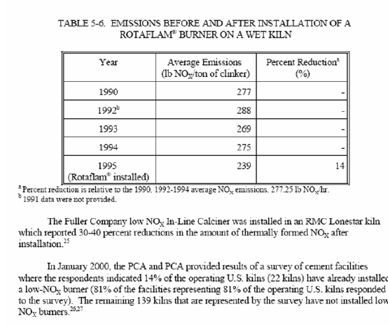
4.1.2. Lafarge experience with low-NOx burners
Specialist and suppliers literature report wide use of low-NOx burners in the cement industry. Lafarge
Cement division has some experiences with Rotaflam burners but without very significant assessment
of Nox reduction
4.1.3. Lafarge experience with NOx reduction via standard burning line optimisation
Considering the limited experience of Lafarge with low-NOx burners, it is interesting to assess the
impact of standard burner operation optimisation & burning line conversion, on the NOx emissions,
through 2 cases studies :
• NOx reduction by flame setting adjustment (trials at Le Havre Plant, Lafarge France)
• Impact on the NOx emission resulting from the conversion of the firing system to an indirect
system (Bath and Brookfield Plants, LNA)
NOx reduction by flame setting adjustment (trials at Le Havre Plant, December 2003)
Conclusions of the le Havre trials were :
• No impact on NOx reduction of the burner transport air flow
• NOx reduction by 30% (1100 mg/Nm3 => 800-850 mg/Nm3) & burning zone lengthening when
cutting swirl air (7000 Nm3/h to 0).
Similar results were obtained at :
• Port-La-Nouvelle plant : -15% NOx reduction by cutting completely the rotational air flow
• Contes plant in 2004 : -30% NOx reduction by reducing both rotational and mainly axial air.
However, other plant trials have shown more mitigated results : attention should be paid on the brick
refractory bricks). Details of trials in Le Havre, St-Pierre-la-Cour & Val d’Azergues, can be found in
Appendix 4.
Conversion of the firing system to an indirect system (Bath and Brookfield Plants, LNA)
In both plants, the former semi-direct firing systems were converted to full indirect firing system with
the installation also of a “Lafarge 3 circuit burner”.
The impact on the NOx emissions on each plant are different :
• In Brookfield : -20% NOx at stack (590 ppm => 480 ppm or 790 mg/Nm3 => 643 mg/Nm3) due to
the lower primary air rate.
• In Bath : no NOx emissions change or slight increase (630 ppm at 10% O2 => 652 ppm or 845
mg/Nm3 => 874 mg/Nm3) with the new burner, due to 2 contradictory effects : reduction of the
primary air, but shorter and hotter flame.
4.2. Flame cooling
4.2.1. Generalities
Adding water in the main flame (via fuel or separate water injection) enables to reduce flame
temperature & increases the concentration of hydroxyl radicals. This can have a positive effect on
NOx reduction in the burning zone : reduction efficiency from 0-50% has been reported.
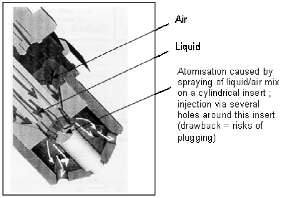
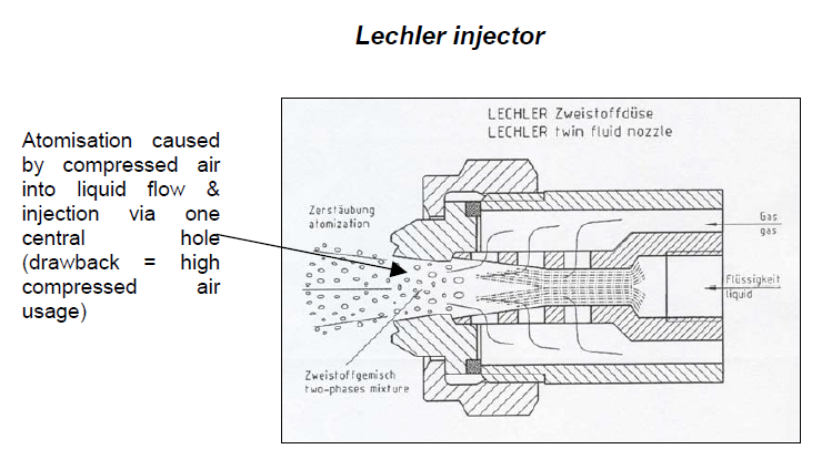
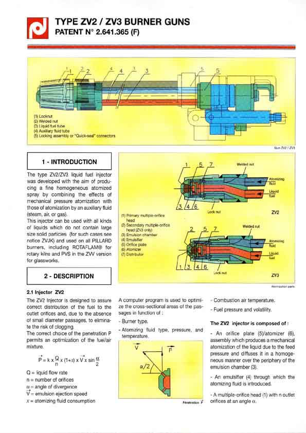
To achieve high NOx reduction efficiency by flame cooling, water or aqueous waste (eg : G2000)
injection should be done through nozzle with efficient atomisation (eg: Pillard ZV2 injectors or
equivalent – picture in Appendix 5) ; it can be done in various locations :
Lafarge recommended solution :
• injection to the center of the flame.
Other alternatives :
• injection on the sides of the flame with a separate pipe.
• injection directly into secondary air, for example in projection onto the clinker as it falls out of the
kiln (first chamber of the clinker cooler).
Important note : Additional heat is required to evaporate the water, which causes slight additionnal
CO2 emissions (approximately 0.1-1.5%) compared to the total CO2 emission of the kiln.
Consequently, water injection causes output loss (due to extra exhaust volume) and if poorly
controlled, can also lead to high free-lime clinker (hence quality of water injection is essential).
For a kiln capacity of 3000 tpd the investment cost can be up 200 k€. The injection of 20l water costs
up to 150kJ/kgkk and reduces the kiln production up to 8%
4.2.2. Lafarge experience with flame cooling
Over the last two decades, many Lafarge plants worldwide (and particularly in the BUs with high
alternative fuels replacement : USA, France, Austria…) have been using solid and liquid aqueous
waste in the main kiln burner or cooler, to get the benefits of the flame cooling with interesting and
variable results concerning the NOx stack emissions.
Detailed reports on flame cooling experiences are available in Appendix 6.
Experience in Lafarge includes :
• G2000 injection at main burner in Val d’Azergues Plant in conjunction with Ademe (a French
Energy and environmental Agency) in 2003 (Guide d’actions de réduction des NOx de l’industrie
cimentière française).
• G2000 aqueous waste trials & permanent usage in main burner in Contes, Val d’Azergues,
Martres, La Malle, La Couronne, Le Teil (France) etc… Similar experience exists as well as in
Richmond, Atlanta (NA) etc…
• Water injection into the clinker cooler and into the main burner in Retznei Plant (Austria)
4.2.2.1. Water or aqueous waste injection in the main flame
In Frangey plant the tests with G2000 (aqueous waste with 75% water content) confirmed the key
points as follows :
• Up to -25% of NOx at kiln stack
• Clinker output reduced by -3% to -7%
• Kiln heat consumption : +35 Th/tkk (= 147 kJ/kg kk)
• Kiln more instable ( volatilisation, longer flame,…)
• No impact on clinker quality
• Optimum results with injection rate of 15-20 litres water per tonne of clinker & central injection in
the burner
However, it seems that the minimum achievable NOx level via flame cooling while maintaining
acceptable burning zone temperature, is about 1000 ppm at the kiln outlet, equivalent to 1000 mg/Nm3
(at 10% O2 dry gas) at the kiln stack . Below this level, there little or no impact of the flame cooling.
This is probably the main reason why flame cooling is applied when the initial NOx stack emissions
are higher than 1300 to 1400 mg/Nm3 (peaks or average values).
The central injection configuration has been successfully tested in other kilns in France in 2004 (Val
d’Azergues, Martres, La Couronne, Contes and Saint Pierre La Cour, for example) with the same level
of results :
• NOx emissions reduction = -20% to -35% at the most
• loss in clinker production = -3% to -8%
These results have become the standard and the target values that are applied for the main burner
flame cooling used in Lafarge.
The tests performed in February 2003 in Richmond plant in LNA with process oily water (at around
500 l/h = 4.35 l/t kk) confirmed these results : more than 30% kiln stack NOx reduction (in comparison
with the 2002 average NOx value). Same levels of NOx reduction were also obtained at Atlanta plant
in 2003 with the production white clinker.
Process water : decanted water from oil separator.
4.2.2.2. Water or aqueous waste injection in the cooler front end
Water injection into cooler chamber 1 at Retznei plant (Lafarge Perlmooser, Austria) was tested in
June 2001 (equipment for the injection installed in 1995).
This 5 stage-test (770 to 1000 kg water/hour = 14-18 l/t kk) aimed at very ambitious emission levels:
• half-hour average < 800 mg NOx/Nm3 : this target was met with injection of 1000 kg/h water
(35% of NOx abatement achieved).
• daily average values < 500 mg NOx/Nm3.
Negative effects were that :
• the tyre feed rate (at the kiln inlet) had to be reduced and replaced by more coal (+ 5%) at the
main kiln burner (detrimental to overall fuel cost & increasing back-end temperature) and
• the ID-fans speed increased by 5% causing additional energy costs.
Effects of an increased water injection (1500 kg/h) could not be investigated due to time constraints
and water nozzle under-capacity.
4.3. Staged fuel combustion
For many years, staged combustion has been traditionally applied to cement kilns equipped with
several combustion stages (generally with specially designed precalciners).
Typically the principle of staged combustion is as follows :
• 1st stage : minimise kiln thermal NOx formation by ensuring optimium combustion in the kiln.
• 2nd stage : decompose & reconvert some of the kiln thermal NOx into N2 by creating a reducing
atmosphere with a burner at the kiln inlet, (ideal t°C for this reaction).
• 3rd stage : minimise calciner fuel NOx formation & further decompose kiln thermal NOx into free
N2, by creating a reducing atmosphere (calciner fuel + substoechiometric amount of tertiary air)
• 4th & final stage : complete combustion of unburnt organics (combustion of CO/VOCs formed in
reducing atmosphere) by feeding the remaining tertiary air
Nevertheless, and particularly since the increased use of alternative fuels in the cement industry, other
kiln processes (preheater and Lepol kilns as well as long kilns) have also used the staged combustion
principle to create slightly reducing atmosphere zones, leading to a NOx reduction. This includes, for
instance, the introduction of a certain amount of solid fuel in the riser duct of precalciner kilns enabling
a reduction in NOx : injecting some fuel at the back-end of Lepol & preheater kiln leads to a reduction
in heat load from the main flame, hence reduce the production of thermal NOx. In addition, replacing a
N-rich fuel with a N-lean fuel (alternative or not) will also contribute to overall NOx emission reduction
through the reduction of fuel-NOx.
Important note : According to Cembureau, staged fuel combustion fuel firing is reported to have a
positive effect on NOx reduction (up to 20 – 30% reduction). However, it is very difficult to produce a
controlled reducing atmosphere when firing low reactivity solid fuels (eg : petcoke) & lumpy fuels (eg :
tyre shreds) : peaks of SO2 and of COV may have to be controlled.
From the above considerations and taken into account the LAFARGE experience on staged
combustion on the above mentioned kiln processes, the Staged Fuel Combustion (SFC) will be split
into he following sections :
• SFC – Precalciners
• SFC – Kiln back end injection (all types of short kilns)
• SFC – Mid-kiln injection
4.3.1. Staged Fuel Combustion – Precalciners
A general description of the principle of precalciner kilns configured for staged fuel combustion has
been given above. According to CEMBUREAU, possibilities with SFC in precalciner are :
• NOx emission levels < 800 mg/m3 achieveable with low reactive fuels
• NOx emission levels < 500 mg/m3 achievable with highly reactive fuels.
• An increase of the CO emissions might occur only in very few plants, designed with relatively short
precalciner residence times or where combustion is not properly optimised .
Suppliers of the different staged firing systems specify possible NOx reductions by up to 50%
However, it is difficult to maintain the guaranteed values for this level of NOx abatement, and limit CO
emissions at the same time.
Costs for installation of SFC (depending on level of modification) :
• The investment cost for installing staged combustion on a precalciner kiln is 0.1-2 M€, depending
on the design of the existing calciner .
• The investment cost for converting a 3000 tpd preheater kiln (with a grate cooler) into a
precalciner kiln with SFC is about 1 to 4 M€.
• The cost for the conversion of a kiln with a satellite cooler into a precalciner kiln with SFC & a
grate cooler is about 15 to 20 M€.
There is limited documented experience within the Lafarge Cement Division on precalciners kilns
configured for staged fuel combustion (see attached bibliography ).
4.3.1.1. Lafarge experience with Minox system
The best known and well documented recent installation is the Minox system (delivered by CLE
Technip) at Port-La-Nouvelle plant in France, where extensive test have been carried out between
1999 and 2001 to check and reach the supplier’s NOx reduction specifications (see Appendix 7 for
details on process & full report).
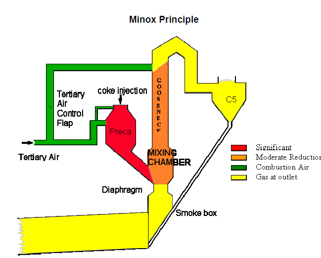
The tests revealed that the NOx reduction efficiency of the Minox is highly correlated with the type of
fuel used in the precalciner (e.g. pet coke and/or combsu, a composite liquid alternative fuel). The
positive correlation between precalciner NOx levels & petcoke injection rate was indeed obvious, with
or without Minox : + 2 tph coke => + 30 % stack NOx emissions. The Minox effect could be quantified
as such :
• 20 % reduction when using 100 % petcoke
• 35 % reduction when using a petcoke / liquid waste (Combsu) mix
However, most of this reduction is not the result of a reduction of NOx by the – HC radicals in the
gooseneck (the principle behind Minox) ; the reduction occurs in the upper zone of the kiln due to the
reducing atmosphere caused by the presence of unburnt residues in the bottom cyclone. In addition,
the Minox operation led to increased cloggings in the kiln back-end (Cardox fired), hence this
technology is not viable in the long-term when using petcoke as main fuel in the calciner.
4.3.1.2. Other Lafarge feedback
Tighter NOx emission limits (and use of AFs) led suppliers to design precalciner with increased gas
residence time, meal staging & tertiary air staging, which have increased the complexity of operation.
The optimum residence time depends upon the precalciner and the fuels burned, as well as the use or
not of SNCR.
For staged combustion, the following minimum additional gas residence time are required :
• 0.5 – 1 second to allow for burn out of CO while keeping NOx emissions < 800 mg/Nm3 (typical for
coal).
• 1 – 1.5 seconds if SNCR is used to further reduce NOx emissions (Research Institute of the
Cement Industry in Germany)
• 3 seconds, with a reduction zone, if more difficult fuels is used, such as petcoke, leading to a total
residence time of 4 – 4.5 seconds. This also should be the minimum residence time for firing
waste fuels
Case studies :
• Trials at Du Jiang Yan, China : the KHD pyro-top with 5 seconds residence time showed the
capability to reduce NOx emission to below 600 mg/Nm3 (corrected) whilst firing normal coal.
Trials on calciner fuel split between pyrotop burner & riser low-NOx burner, showed that it is
possible to lower NOx emissions by maximising the calciner fuel split to the low-NOx burner :
o NOx < 800 mg/Nm3 @ 10% O2 achievable on continuous basis with 70% of calciner
fuel injected via riser low-NOx burner (instead of 62% initially)
o 507- 554 mg/Nm3 @ 10% O2 achieved with 100% of calciner fuel injected via riser
low-NOx burner hence this technology would not be sufficient if a limit of 500 mg/Nm3
was to be respected.
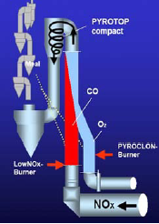
Configuration of the KHD Pyrotop calciner in DJY plant : the Pyroclon burner is located in the Tertiary air
duct (in oxidising atmosphere), while the low-NOx burner is located in the riser duct (in reducing atmosphere).
The impact on NOx emissions, of the variation in % of calciner fuel injected via the riser low-NOx burner is
shown on the graph next page.
The complete study is available in Appendix 8
• Trials at Sugar Creek, USA : the Polysius Prepol with combustion chamber, air staging and 6
seconds residence time, whilst firing coal showed that a reduction atmosphere in the combustion
chamber can lower the NOx produced in the combustion chamber, but has no impact on reburning
the kiln NOx. Therefore, firing of some fuel into the kiln riser will be necessary to achieve a NOx
level less than 800 mg/Nm3, if SNCR is to be avoided.
4.3.2. Staged Fuel Combustion – Back-end injection
Staged combustion via back-end injection of fuels (fossil or AFs) for Lepol & preheater kilns is another
option to reduce NOx stack emissions.
Several effects can explain the reduction of the NOx levels achieved when using fuel back-end
injection techniques, among them the more important are the as follows :
• Effect of heat load split : When shifting some of the heat load from the main burner, to the backend,
the excess air at the main flame (necessary to maintain stoechiometric-combustion overall) is
so high that flame cooling takes place, hence slowing down the formation rate of thermal NOx.
According to a study by Ökopol (Institut für Ökologie und Politik GmbH, Sept 98), the shift of
energy input from front end to back-end can lead to a 10% to 30% NOx reduction on Lepol or
preheater types of kilns.
• Effect of Nitrogen-lean, high-volatiles fuels injection at back-end : in the back-end of preheater
kilns, only fuel NOx are formed (temperature too low for thermal NOx) ; from the N% of the backend
fuel : therefore minimising the N% of the back-end fuel reduces the potential for fuel-NOx
formation. In addition, to minimise the production of fuel NOx, rapid increase of temperature is
necessary so high-volatile fuels are best in that respect.
Impact of tyres on NOx emissions :
TDF (Tyre-Derived Fuel) creates local reducing conditions (absorbs all the O2 available) to combust
properly, which breaks down the kiln thermal NOx, back to free nitrogen.
In addition, TDF has an effect on fuel-NOx due to its N% & volatile % :
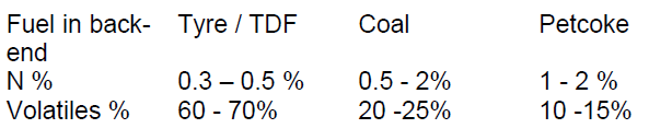
Conclusion on effect of tyres on fuel- NOx in back-end Lower fuel NOx formation potential
Higher temperature increase hence lower fuel-NOx formation rate
In the last decade many Lafarge kilns (all types of short kilns) have been using different alternative
and/or conventional fuels in the back-end & on Lepol grate. However, the only documented feedback
on the impact of this technology on NOx emissions, are those recorded in the last 3 to 4 years for
tyres (whole and mainly shreds and chips tires) & liquid alternative fuels (G2000 mainly & G3000).
4.3.2.1. Lafarge experience with tyre injection at back-end
Generally speaking, Lafarge experience shows that the use of tyre-derived fuel or TDF at the kiln
back-end, enables to reduce NOx emissions by 0 to 30%, but deteriorates combustion (increased
volatilisation caused by coarse fuel entering the kiln : higher kiln inlet SO2 & CO, sometimes higher
emissions of SO2 at the stack, which can be controlled via kiln draught & TDF feeding optimisation).
In the UK, the permitting procedure for alternative fuels usage is quite heavy, hence a number of tests
have to be done before the plant can apply for a permit. Therefore, we have back-end tyre injection
trial data for :
• Dunbar (Trial for permanent use of tyre chips at max 4 tph – 01/01)
• Cauldon (Trial for permanent use of tyre chips at max 7 tph – 09/01)
• Cookstown (Trial for permanent use of whole tyres on fingers at max 12% substitution – 03/02)
• Hope (Trial for permanent use of tyre chips at max 2 tph – 08/02)
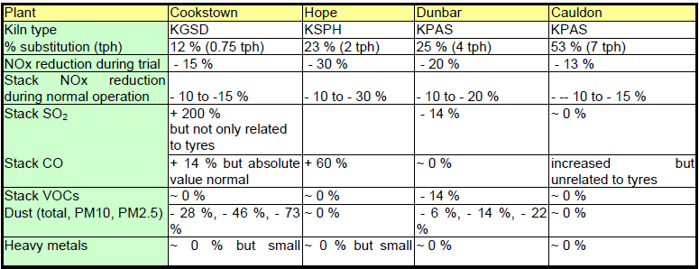
A table in Appendix 9 lists the Lafarge plants, which inject TDF at the back end of their kiln and shows
what effect the average yearly substitution rate had on their NOx emissions.
More recent documented tests and follow up on the impact of back end tyre chips injection (Bouskoura
2 Plant in 2004 and Hope 2 Works in 2003 ) have confirmed the above results :
• Bouskoura kiln 2 (CTEO report n° 2004-11135A, april 2004, by C. Bignolas, in EASI TC
database): the injection of 2.5 t/h of shredded tyres in the smoke chamber lead to a 22% reduction
of the stack NOx emissions compared to 100% petcoke in the back-end. As backward effects, SO2
and CO have increased at the kiln outlet (effect on stack SO2 & CO not measured). To respect the
1200 mg/Nm3 limit applied in Bouskoura, the kiln NOx must be < 1200 ppm (if coke only) & <
1500 ppm (if coke+tyre chips).
• Hope Works (CTEO report n° 2004-10926, sept. 2004 in EASI TC database): the influence of
secondary fuel injection (tyres versus coal) was tested on kiln 1, with a fixed total amount of fuel
(1.5 t/h). During the trials NOx levels were reduced between kiln exit and stage 4.The more tyres
were used, the greater the reduction :
o – 10% with only coal,
o -18% with 0.5 t/h tyres and
o -32% with 1.5 t/h tyres.
However , the use of tyres led to a deterioration of combustion : increase in kiln exit SO2 (even
with higher O2), increase of CO in stage 4.
• La Malle whole tyres injection. The La malle kiln is incinerating whole tyres (<10% of total
combustible) for more than 10 years. Some trials (summarized in the following table) demonstrate
the positive impact of tyres injection on Nox (50% reduction), compensated by an increase in SO2
emission (doubled).
4.3.2.2. Lafarge experience with liquid alternative fuels injection at back-end
A successful and well documented case is the injection at the Lepol grate of G2000 (aqueous waste)
and G3000 (alternative fuel mainly composed of solvents), from a report issued by the ADEME, a
French Energy and environmental Agency, in 2003 : “Guide d’actions de reduction des NOx de
l’industrie cimentière française”.
The results of these tests show that :
• with G2000 injection on Lepol grate : about 10% of stack NOx reduction can be achieved.
However the kiln process and production are penalized by the high extra load of gas that has to
be exhausted (G2000 moisture > 80 %)
• with G3000 injection on Lepol grate : about 10% to 25% of stack NOx reduction can be achieved,
depending on G3000 injection rate (200 to 500 liters/hour). The maximum temperature that the hot
chamber can stand is the limitation to higher usage of G3000 (must remain < 1100°C).
Additionally, the residence time above 850°C in the Lepol grate may not be long enough to be
sure that all the organic components of the waste are destroyed.
Conclusion on back-end injection of AFs
All the above results (tyres and other alternative fuels) confirm the literature data on the impact of back
end fuel injection on different kiln processes (precalciner, preheater, Lepol grate kilns) : a reduction of
the NOx stack emissions up to -30%, but more generally comprised between –10% and –20%. Also
they confirmed that the levels of SO2, CO and COV have to be controlled.
4.3.3. Staged Fuel Combustion – Mid-kiln injection
4.3.3.1. Waste fuels injection via Mid-kiln
Mid kiln injection is the introduction of some of the fuel in a cooler zone than the flame, in long wet and
long dry kilns. Fuels injected can include municipal waste, tires or hazardous waste in drums. This
technique enables NOx reduction via 3 effects :
• Fuel split : less heat at main burner means less thermal NOx formed (no thermo-NOx formed in
mid-kiln zone due to too low temperature)
• Main flame NOx destruction : the local reducing conditions in mid-kiln zone (caused by coarse fuel
combustion) decompose NOx back to free N2
• Flame cooling : high excess air at main burner (to provide sufficient O2 overall) may cool the flame
hence lower NOx formation rate
Points to watch :
• Too slow burning fuels => risk of strong reducing conditions leading to quality problem
• Too quick-burning fuels => risk of high fluctuations & chain damage (too high temperature at backend)
These means of mid-process firing have received favorable review with respect to NOx reduction in
environmental official documents such as the BREF-BAT in Europe and :
• the EPA documents in USA. :
o dry kilns NOx reduction : 33% avg (11-55%)
o wet kilns NOx reduction 40% avg
• Cembureau :
o average reduction : 20-40%
Capital costs may be in the region of 0.8-1.7 M€ for the kiln conversion and fuel handling equipment,
and the annual operating costs may be of a similar order (Cembureau sources).
4.3.3.2. Lafarge experience with injection of whole tyres, limestone, slag & bottom ash via Mid-kiln
Within the Lafarge Cement Division , Mid Kiln Injection of waste fuels at different plant locations has
demonstrated some levels of NOx reduction. Detail trials results are available in Appendix 10.
EPA has summarised this NOx reduction by giving a range of 20 to 40%. Lafarge has historically
used 20% which is a conservative estimate. We should not forget to look at the impact on SO2 when
using tyre injection through mid kiln. Non Lafarge results are given in Appendix 11.
Note : Injection of limestone, slag & bottom ash via dust scoops has also been tested in Paulding,
resulting in NOx reduction to a lesser extent that tyres or urea, but enabling increased production.
Details of trials are available in Appendix 12.
4.3.3.3. Mixing Air Fan (Cadence)
Although Cadence claims their MAF reduce NOx emissions though creation of reducing atmosphere,
the Mixing Air Fan (MAF) has demonstrated increases in tyre substitution rate but no change in NOx
emissions. The tests in St-Constant (early 2004) and Joppa, with kilns already burning tyres, led to the
following conclusions :
• increased tyre substitution rate (St-Constant : 15% in 2003 => 23% with acceptable chain gas t° of
924 +/- 8 °C < 950 °C ; chain gas t° used to be the limiting factor for higher rate in St-Constant),
• lower Chain Gas Temperature (-15 to -20°C, caused by mixing effect rather than MAF fresh air
input of 6000 Nm3/hr => dilution would only lower t° by 2°C)
• no output loss nor quality issue,
• no reduction in NOx emissions (nor in SO2 or CO, after 2 months operation).
A picture of the MAF is available in Appendix 13.
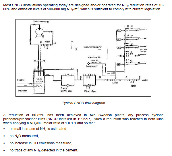
4.4. SNCR (Selective Non Catalytic Reduction)
4.4.1. Generalities
SNCR process has been known for long time (Exxon, 1974) and has been applied in different
industries including cement industry for NOx reduction.
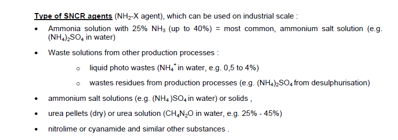
Principle of operation of SNCR :
• Injection of NH2-X compounds into the combustion gas to reduce NO & NO2 (not N2O, this is why
it is called “selective”) to N2 (no catalyst)
• optimum efficiency in temperature window usually around 830-1050°C (but up to 800-1150°C
depending on reagent),
• sufficient retention time in the right t° window to be provided for the injected agents to react with
NO. Indeed, if these criteria are not respected :
o risks of ammonia slips if t° too low (NH3 slip occurs when unconverted ammonia is
emitted because there is not enough time in the right t° window) or if elevated NH3/NO
molar ratios (above 1.0-1.2)
o risks of more NOx formation if t° too high (ammonia oxidised into NOx).
The right temperature window & retention time are easy to obtain in suspension preheater kilns,
precalciner kilns and in Lepol kilns, unlike in long wet and dry process kilns (very difficult to obtain
these criteria).
Details of SNCR principle is described in Appendix 14.
Important note : the quality of atomisation is essential to ensure optimum efficiency of the SNCR
system. Details of liquid SNCR installation like those in CTEC region and advice on operational layout
are given in Appendix 14.
Effects of poorly controlled SNCR :
NH3 slippage has in other sectors of industry sometimes resulted in the formation of aerosols of
ammonia chlorides and ammonia sulphates which has passed through the filter and become visible as
a white plume (or blue haze) above the exhaust gas stack. Unused ammonia may be oxidised and
transformed into NOx in the atmosphere and NH3 slippage may also result in ammonia enriched dust
which may not be recycled to the cement mill (smell problem).
Experience with SNCR worldwide :
By 2004 they were around 30 full-scale SNCR installations in operation in European countries and the
total number by the end of 2005 should reach around 80 (Cembureau sources).
The experience of this plant shows possibilities with SNCR but is not really applicable to most other
cement kilns, which usually do not have a SO2 scrubber, not enough residence time in the 830-1050°C
temperature window. Further development in the use of SNCR technology is necessary if the plant is
already equipped with a staged combustion system. Simultaneous use of these technologies requires
the temperatures, retention times and gas atmosphere in the reaction section to be adjusted to suit
one another.
4.4.2. Lafarge experience with SNCR
From the Lafarge experience gained the last years, mainly in CTEC zone, it appears that to achieve a
NOx emission level between 500 and 800 mg/Nm3 (dry, 10%O2), the SNCR option has turned out to
be one of the most viable technologies. Indeed, it gives high flexibility for kiln operation (control of O2,
burner adjustment), alternative fuels and stakeholder relationship (image, permitting). This flexibility is
partly compensating the high operating costs associated with SNCR.
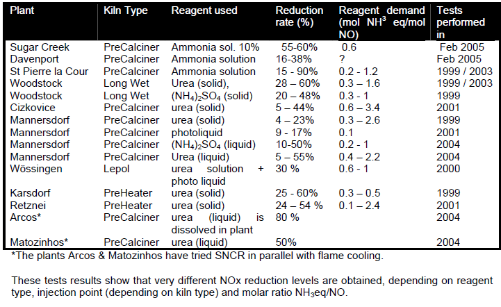
4.4.2.1. SNCR tests in Lafarge
Many Lafarge plants around the world have performed industrial tests applying the SNCR principles,
as shown in the table below (note : not all the tests have been reported). In some plants the tests have
triggered an investment into a full scale installation. This is especially true for regions, where the NOx
emission limit is set very low (e.g.: 500 mg/Nm³, dry, 10% O2 valid for half-hourly average value) and
the technical boundary conditions do not allow primary measures to reach this limit.
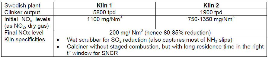
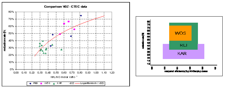
4.4.2.2. Industrial scale SNCR installation in preheater kilns
More documented and full-time operating SNCR systems in Lafarge (1-3 year old) are the installations
in CTEC region, in :
• Retznei, Austria (Polysius DOPOL 4 stage preheater kiln), existing
• Wössingen, Germany (Polysius LEPOL grate kiln) and
• Karsdorf, Germany (KHD 4 stage preheater kiln) .
A CTEC technical info paper (May 2004) summarises the experiences collected with these 3 industrial
installations and is available in Appendix 15.
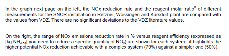
The table below shows the difference between complex SNCR system with liquid reagent, multiple
injection points (Retznei & Wössingen), which is required for difficult kiln operation (waste usage at
back-end, Cl-bypass, low residence time in 800-1150°C t° window…) and simpler system with solid
reagent which can be used in case of easier kiln operation (Kardsorf).
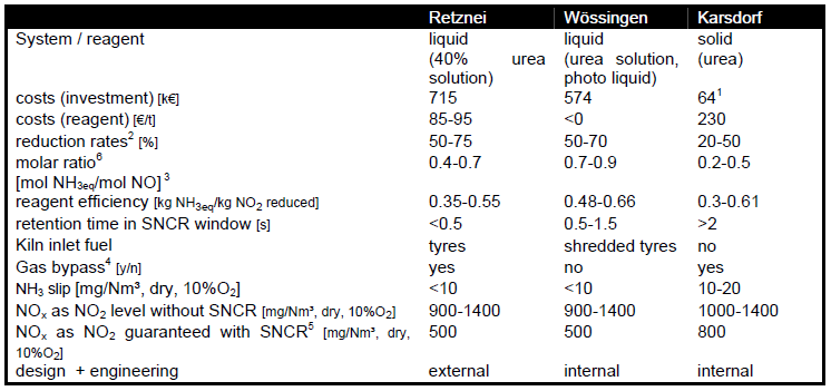
1 For both kiln lines the total investment was 120 [k€]
2 Reduction rate is related to the already practically performed reduction rate
3 NH3 eq is used to make different reagents comparable, as the reacting part of each reagent is always some form
of NHx
4 As the kiln gas (including NOx from kiln) is extracted before the SNCR installation, some NOx is also bypassing
the SNCR installation being not reduced.
5 The guaranteed level has already been proven in Retznei & Wössingen
6 Molar ratio: NH3 molar flow /NO molar flow (baseline level)
Other experience with preheater kilns in Lafarge :
More recently (October 2004) a new SNCR full-scale installation started operating in the precalciner
kiln of St Pierre-La-Cour (SPLC), France. The results obtained in SPLC in the first six months
confirmed the very good efficiency and flexibility of this NOx emission abatement technique. The key
production figures for the first 6 months of industrial operation of SPLC SNCR are as follows :
Reagent used : Reduktan A200 (ammonia solution @ 25% in CTEO zone, 115 €/t )
NOx level at kiln stack : reduced from 1200 mg/Nm3 (no SNCR) to 600 mg/Nm3 (SNCR)
Cost : 0.42 €/t kk
Additionnal experience is available as SNCR trial reports in Sugar Creek (Appendix 16) and
Davenport (Appendix 17).
4.4.2.3. SNCR installation in long kilns
The SNCR process was also tested for wet kilns : e.g. in Woodstock plant, Canada (tests in 1999,
2003 – see Appendix 18) using the dust scoops to add solid urea / ammonium sulfate after chain zone.
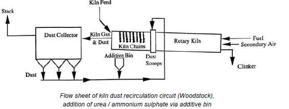
The achieved reduction rates have been in a range of 20-60% related to a reagent demand of 0.2-1
[kmol NH3/kmol NO]. It is important to note that Kiln 2, where the dust scoops are located closer to the
burning zone than the Kiln 1 dust scoops, showed a higher NOx reduction potential.
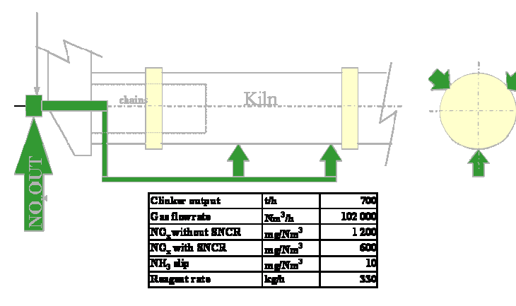
An other plant in Holcim group, located in Lumbres (France), has tested amonia injection in their long
wet kiln with chains, with Fuel Tech (SNCR supplier). The injection of the reagent (45% NH3) is done
via a rotating seal and led to a 50% reduction in NOx emissions, from 1200 to 600 mg/Nm3 (11% O2).
The sketch & table below summarise the test conditions & the graph of NOx, CO, O2 variation thanks
to SNCR is shown in Appendix 19.
How to choose between the two systems of SNCR available?
• Simple SNCR system with 1-2 injection points, injection of “easy to handle” reagent (e.g.: solid
urea), simple instrumentation & storage / injection equipment, or,
• Complex SNCR system with several injection points, high flexibility for “more complex” reagents
(e.g.: solutions, photo liquid…), complex safety & environmental protection equipment.
The solid urea is the most suited equipment for long kiln equipped with scoops. For the other kilns, the
liquid systems are recommanded.
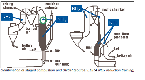
4.4.3. Future development : SNCR in combination with staged
combustion
SNCR with staged combustion needs some further development due to the contradiction between the
2 techniques :
• staged combustion relies predominately on the creation of a reducing atmosphere, whereas
• SNCR process operates in the presence of excess oxygen.
Therefore a combination of these two processes can only be achieved by separation of the reaction
zones. In practice, VDZ has investigated a combination of these two processes together with Polysius
and KHD on their precalciner systems. The sketch below shows were NH3 injection has been tested.

4.4.4. Conclusions on SNCR
SNCR is a proven & efficient technology for NOx emissions reduction in preheater kilns. Further
investigation are however needed on :
• the impact of reagent type on reduction efficiency (& costs),
• possibilities of NOx reduction in long kilns &
• combination of SNCR & staged-combustion.
5. End-of-pipe NOx reduction :SCR technology (Selective Catalytic Reduction)
SCR (Selective Catalytic Reduction) is presently not considered as “Best available technology (BAT)”
in the cement industry (Cembureau). Nevertheless there are long term experiences in other industries
(power generation, waste incineration…) proving SCR as state-of-the-art for these applications.
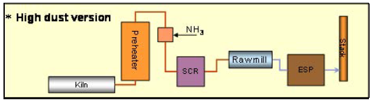
5.1. Principle of SCR
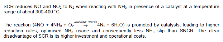
In the cement industry, SCR process is taking place in a temperature range of 290-420 [°C]. Based on
this there are two possible designs to apply SCR in cement industry:
• low dust exhaust gas or tail-end configuration &
• high dust exhaust gas configuration.
5.1.1. Low dust exhaust gas configuration
The low dust exhaust gas system :
• enables the catalyst to operate in a clean atmosphere hence gives higher catalyst lifetime & lower
operational costs (less wear / scaling of catalyst surface), but
• requires reheating (with burner) and heat recuperation (with gas-gas heat exchanger) of the kiln
exhaust gases (as gases at filter exit are too cool for catalyst efficient operation), resulting in
additional investment cost
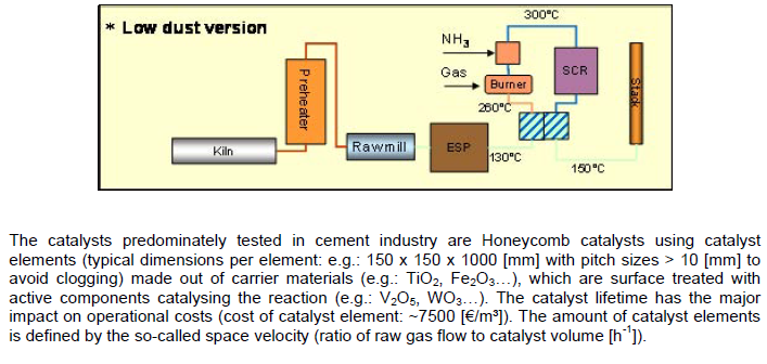
5.1.2. High dust exhaust gas configuration
The high dust system :
• operates in a dirty atmosphere (located in dusty preheater exhit gas) hence catalyst surface wears
much quicker, but,
• does not require any reheating since the catalyst is located in the right temperature window for
efficient operation.
These systems are currently considered preferable for technical and economical reasons.
5.2. Experience of SCR in the cement industry
In the late 90’s, several plants made tests with SCR in high dust configuration, using a small amount
of preheater gas (in conjunction with Austrian Federal Environmental Agency).
These tests could partly demonstrate a basic suitability of catalytic NOx abatement : high reduction
rate achievable while minimising NH3 slip. However, all tests could not answer the question on activity
loss of the catalyst over longer operation time, reliability of equipment and costs. In some tests the
loss of activity even resulted in the conclusion that SCR is not feasible partly due to poisoning of
catalyst by alkali salts and Thallium oxide.
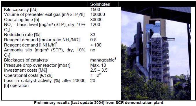
5.2.1. SCR permanent operation at Solnhofen
Sponsored by the Federal Environmental Agency and together with mg engineering Lurgi, Solnhofen
cement plant (Germany) decided to do a next step and build the first industrial scale SCR
demonstration plant in cement industry, which was started up in 2001.
In the first year, the plant encountered occasionnal issues (eg : pluggings of catalyst due to high dust
load, up to 800 g/Nm3) & focussed on SCR process optimisation (dedusting units, air supply, type of
nozzles, modes of operation, pitch size of the catalyst, etc…).
Solnhofen SCR system is now operated continuously to comply with the 500 mg/Nm3 limit (German
regulation, which applies when significant modification of process is made) but has also proven shortterm
efficiency to achieve 200 mg/Nm3. However, there is not long-enough experience to properly
assess operating cost associted with SCR, nor the long-term efficiency & the impact on cost of running
continuously at 200 mg/ Nm3.
Details of feedback : The raw gas (average dust burden = 80 g/Nm3) passes through the catalyst at a
temperature of 310°C ; a by-pass enables to start-up & shut-down the system safely. The preliminary
results of 30 000 hours of operation (approx 3.5 years cumulative duration) are shown in table next
page.
5.3. Cost of using SCR
A cost evaluation (UmweltMagazin 01/02.2004; Herden, Sauter, Haug and Samant) of the SCR and
SNCR technique stated that :
• for NOx emissions target < 800 mg/Nm³ & > 500 mg/Nm³, a SNCR system is equal or even more
economic than SCR system.
• for NOx emissions target < 200 mg/Nm³ or a removal efficiency of 85 %, SCR is quoted as being
more cost-effective. The conclusion for NOx emissions target between 200 & 500 mg/Nm³ is not
clear yet.
Note : the details of assumptions made for calculation are not available
Another cost estimation of the German cement industry (VDZ) has been made & comprises a more
detailed approach concerning the costs of SCR technique :
• investment costs
• operating costs including :
o costs for ammonia water,
o power consumption due to compressed air for the cleaning of the catalyst
o the pressure drop due to the catalyst itself along with other cement plant typical
economic assessment figures
——————————————————————————————
7 SCR has partial potential to utilize raw material based ammonium as reagent in the reduction process.
8 after problems in the first months, the plant could optimize the cleaning device and catalysts geometry, resulting
in reliable operation up to 100 [g/Nm³] dust load in preheater exit gas.
9 The costs are different due to different sources: more optimistic by Federal Environmental Agency, more
pessimistic by Cembureau, VDZ
The conclusions were that :
• only if electricity costs are low & ammonia prices high, SCR becomes as “cheap” as SNCR. This
situation however does not apply for EU region, since ammonia and energy costs tend to follow
the same trend.
• efforts to reduce NOx by primary measures (~ 800 mg/Nm³ as average now in Germany) led to
better economics for SNCR, which costs are largely influenced by the cost of ammonia. Therefore
the specific costs for NOx abatement is in a range of 0,25 to 0,75 €/t clinker (SNCR system),
dominated by the cost for reagent.
General findings :
• SCR investment costs = 4 to 9 times higher than for a SNCR system.
• SCR operating costs = 1,25 to 2,00 €/t, depending on plant size and NOx removal efficiency
required (catalyst replacement is the major operating cost but energy consumption is also a
significant cost – caused by the pressure drop and cleaning air for the catalyst).
• however this technology is evolving and recent developments are enabling to reduce costs, as
higlighted in the variation in specific SCR cost : 3 €/t kk from earlier VDZ study against around
1.75 €/t kk now.
Altogether one can say that only if specific circumstances require a NOx-level of 200 mg/Nm³ and the
technical situation for applying SNCR or other measures is unfavourable, a SCR system might make
economical and ecological sense.
If the catalyst is designed accordingly, SCR will in general also reduce VOC and PCDD/Fs. According
to one supplier, new pilot projects for NOx reduction are being developed in which specific catalysts
are applied for the additional reduction of VOC and CO emissions (Dutch report, 1997).
5.4. Conclusion on SCR
Additional to the several pilot-scale SCR trials, which have been carried out, the operational results of
the first demonstration plant installed in Solnhofen support the applicability of SCR at cement kilns.
Today SCR is not regarded as BAT, but the new update of the BREF in 2005 will include a new
assessment of SCR. So we have to face the risk that authorities will consider that extra costs
associated with SCR are acceptable and can be compensated by our savings / earnings from
alternative fuels usage.
6. Economical aspects
6.1. Cembureau estimates
The table hereafter (Cembureau sources updated in June 2005) gives an overview of techniques that
have a positive effect (but not necessary cumulative) on the emissions of NOx from cement kilns.
The table is a summary and should be read in conjunction with the corresponding chapters above.
Process-integrated measures :
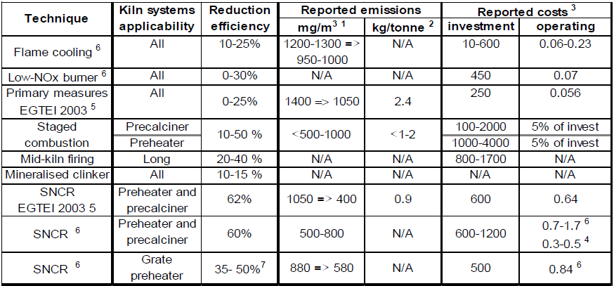
End-of-pipe measures :
1) normally referring to daily averages, dry gas, 273 K, 101.3 kPa and 10% O2
2) kg/tonne clinker : based on 2000 m3/tonne of clinker
3) investment cost in k€ and operating cost in €/t kk, normally referring to a kiln capacity of 3000 tonne
clinker/day and initial emission up to 2000 mg NOx/m3
4) costs estimated by Cembureau for a full scale installation (kiln capacity 1000 to 5000 t/d)
5) EGTEI cost estimation for a kiln capacity 1100 t/d
6) Experimentation programme in France in cooperation with Environment Ministry, Ademe and ATILH
in 2000 (issue 2003)
7) WÖS has been operating for 1 year, complying with an emission limit of 500 mg/Nm³, dry, 10% O2.
As the baseline NOx level before installation of SNCR with similar operation conditions was ~ 1000
mg/Nm³, dry, 10% O2, the installation has proven to be capable to reduce NOx continuously by ~ 50%.
6.2. Lafarge estimates
The table hereafter summarises the internal Lafarge data available and recorded in formal reports
issued over the last 3 years. This table is only a summary and should be read in conjunction with the
corresponding chapters above.
1) Investment cost in k€ and operating cost in €/t kk
2) Val d’Azergues Plant installation for G2000 ( includes also the system to feed the Lepol grate)
3) Minox system of Port La Nouvelle Plant (the investment cost would be for a Minox system added to
a kiln already equipped with a precalciner )
4) Average cost of 7 G2000 installations erected in France between 1988 and 1998 ( Martres,
Frangey, Le Havre, La Teil, SPLC and Val d’Azergues), the cheapest being 380 k€ and the more
expensive 660 k€
5) Average cost of three G3000 installations erected in France between 1988 and 1998 ( La Malle ,
Frangey and Val d’Azergues), the cheapest being 1.2 M€ and the most expensive 2 M€
6) The average cost for the LCUK installations (excluding Dunbar) is 2.34 M€ (Hope with 2 kilns and
Cauldon). Dunbar investment cost was 5.1 M€ including the shredding facilities. La Malle plant
investment (whole tyres) was 2.7 M€ in 1992. Le Havre solid shredded wastes (SSW) back-end
injection system was 1.6 M€ in 1994. More recently, La Couronne project budget for SSW is 1.9 M€.
7) Investment cost from 2.6 M€ (Joppa Plant, LNA) to 4.3 M€ (Westbury Plant, LCUK ), in both cases
2 kilns were equipped. The operational cost is a reduction in the fuel cost in Joppa Plant resulting in
lower cement bin cost of $ 1.00/ metric ton (at nominal tire rate of 18%, 1.4-1.8 tph)
8) From the installations done in Austria (Retznei), Germany (Wössingen and Karsdorf) and France
(SPLC). The 0.031 €/t of clinker figure correspond to Wössingen plant where the reagent is a mix of a
waste (photo liquid product) with a negative cost (-4.8 euros/t) and urea solution.
9) high range estimated from fee of whole tyres (paid 60 €/t to plant & used at 20% substitution) & 0.2
€/t for operating costs of system but can vary a lot, depending on manpower required & gate fee.
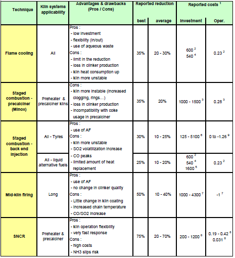
7. Conclusions
Primary measures such as raw mix burnability optimisation, burner settings optimisation or flame
cooling should always be investigated first & be reviewed regularly.
Secondary measures implying major process modifications (staged-combustion, low-NOx calciner
retrofitting…) should be considered in case of requirement for drastic change in NOx & where the
modification has other process benefits, since these are rather expensive (1-1.5 M€). Operating costs
might however be reasonable.
AFs usage at the back-end & mid-kiln, although investment can be expensive (mid-kiln), is an
efficient way to combine NOx reduction effect with fuel bill savings, but the potential increase in SO2 &
VOCs emissions will need to be properly controlled.
SNCR is the most cost-effective route to go for plants, which can not comply with their NOx emissions
limit with primary measures only. It is considered as a BAT (due to their number in Europe, i.e. 80
units by end 2005) and their performance, as opposed to SCR.
8. Bibliography
• NOx regulation, Emerging regulations & trends : CTEO Environment presentation by Rogelio
Dupont 16/04/2004
• NOX Control Technologies for the Cement Industry, EPA Contract No. 68-D98-026, Prepared
by: Rebecca Battye, Stephanie Walsh, Judy Lee-Greco (EC/R Incorporated, Chapel Hill, NC
27514) – September 19, 2000
• NOx reduction by Staged Combustion in Precalciner : ATC report 27/10/2004, by Simon Rice
(ref TSP_ATC600STUNOX_SGR_271004_DJY TA NOx Reduction.doc)
• Projet ADEME de réduction des NOx par injection de G2000/eau à Val d’Azergues (in EASI
TC Documentation database, ref n° CTLC 2001 06607A), C. Bignolas, 21/12/01
• Minox 3rd trial in Port-la-Nouvelle (in French & in English, EASI TC Documentation database, ref
n° LC-2001 06278C), C. Bignolas, 24/08/01
• Essai réglage tuyère pour réduire le NOx à Saint-Pierre la Cour : EASI TC Documentation
database (in French), ref n° CTEO-2004 11588-A, by Armando Da Silva, 7/12/2004
• Economic evaluation of NOx abatement techniques in the European Cement Industry
(Ökopol): Final Report September 1998, by Jan Wulf-Schnabel & Dr. Joachim Lohse
• CTS, Michael Beaupre, Lafarge Canada, Scarth Macdonnell, Lafarge Corp., Michael Nisbet;
“Non-Catalytic Reduction of NOx In A Wet Kiln”
• Woodstock plant, Shervan Khanna; “2003 Urea Injection Trial Results”, October 2003
• ZKG (Volume 54), D. Rose, K. Adler, R. Erpelding; “NOx abatement with SNCR process in kiln
plants with staged combustion”, July 2001
• ZKG (Volume 54), V. Hoenig, H. Hoppe, N. Bodendiek; “Options and limitations in NOx
abatement in cement industry, Part 1”, April 2001
• ZKG (Volume 54), V. Hoenig, H. Hoppe, N. Bodendiek; “Options and limitations in NOx
abatement in cement industry, Part 2”, July 2001
• ECRA, VDZ, “ECRA Training: NOx Reduction – Seminar S04-01”, March 2004
• CTEC, W. Kurka, K. Ladenhaufen, H. Reiterer; “CTEC Technical Info Paper: Selective Non
Catalytic Reduction of NOx emissions”, May 2004
• CTEO, R. Huard, C. Bignolas; “Etude sur l’injection de NH3 à St-Pierre-La-Cour”, November
2001
• Retznei + CTEC, V. Ruprecht, W. Kurka; “CTEC Study Statement: NOx reduction (urea
injection) in Lafarge Perlmooser plant Retznei”, August 2001
• Mannersdorf + CTEC, G. Woltron, W. Kurka, “CTEC Study Statement: NOx reduction plant
Mannersdorf: SNCR trials with photoliquid”, August 2001
• Gefahrenstoffe – Reinhaltung der Luft (Volume 61), J. Lohse; “Estimated costs and benefits of
improved dust and NOx abatement in European Cement Industry”, July/August 2001.
• “Tyre synthesis” in Resource Recovery database, ERN, 2003
• Sugar Creek SNCR test report by Polysius
• Davenport SNCR test report by FLS (Feb 05)
9. Appendices
9.1. Regulation on emissions & units conversion
• This document is an overview of recent regulation on industry emissions likely to impact our
cement activity & was presented by Rogelio Dupont at the CTEO Process days in April 2004.
• Conversion of emissions units into various standards & conversion formulas (wet to dry, ppm to
mg.Nm3, O2 correction…).
9.2. Details on NOx formation mechanisms
Some background on NOx emissions :
• Generally NOx emission is typically in the range of 500 to 1 500 ppmv being closely related to
kiln combustion conditions.
• In the cement industry normally at least, 95 % of NOx formed is nitric oxide (NO). This gas is
colourless and is readily transformed by oxidation into NO2 in air.
• Nitrogen dioxide (NO2) is a reddish -brown gas and is the principal components of smog. The
toxic effects of NO2 are not completely known, but an exposure to 15 ppm NO2 causes eye
and irritations and 25 ppm causes pulmonary discomfort.
• NOx is the generator of acid rains as in the SO2 emissions.
• Nitrous Oxide (N2O) represents < 1 % of NOx produced in a cement kiln. It is very stable and
is considered to play a role in the destruction of stratospheric ozone layer.
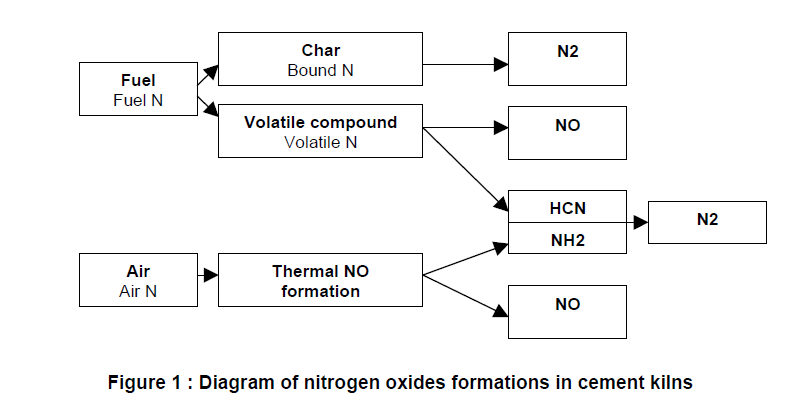
There are three main sources for production of NO:
• Thermal NO
• Fuel NO
• Prompt NO
Only thermal NO and fuel NO are produced at significant levels in the cement industry.
• Thermal NO : Part of the nitrogen in the combustion air reacts with oxygen to form various
oxides of nitrogen.
Fuel NO : Nitrogen containing compounds, chemically bound in the fuel, react with oxygen in the air to
form various oxides of nitrogen
Thermal NO Formation Mechanisms
Thermal NO is defined as that portion of the oxides of nitrogen that originate from the fixation of
atmospheric nitrogen.
Its formation depends on :
• Combustion air temperature
• Excess air
• Residence time in the combustion zone
• Temperatures homogeneities
Temperature effect
Excess air effect Thermal NO results from the oxidation of N2 in the air, as it passes through flame. A
high temperature is required for it to form, and this why it is referred to as “ thermal “. Thermal NOx
forms essentially at temperatures above 1600°C and involves the reaction of nitrogen and oxygen
molecules in the combustion air. Its formation is not produced on the heart of flame, but immediately at
the end of this flame.
In cement plants, in order to get the clinkerisation of the raw mix, it is necessary to reach the high
materials temperatures in the range : 1 400 °C – 1 500 °C, which could lead to the maximum flame
temperature of 1 900 – 2 000°C.
Thermal NO is produced mainly in the kiln burning zone where it is hot enough to achieve this
reaction. The amount of thermal NO produced in the burning zone is related to both burning zone
temperature and oxygen content (air excess factor). The rate of reaction for thermal NO increases with
temperature; therefore, hard-to-burn mixes which require hotter burning zones will tend to generate
more thermal NO than kilns with easier-burning mixes.
Excess air effect
The formation of the good clinker requires an atmosphere oxidant for several reasons :
• Volatilisation ( builds ups, concretes…)
• Formation of iron divalent in reductive atmosphere, harmful to alite stability – essential
constituent of Portland clinker
• Complete combustion
Increase of excess air causes an increase of the NO production so long as there is no important drop
of the combustion temperature products at the end of the flame reaction zone.
The curve given below states the concentration of thermal NO at equilibrium as a function of excess
air and temperature.
Figure 2 :
Theoretical equilibrium of thermal NO concentration as a function of temperature & O2
Effect of residence time
The conjunction of the high material temperature and the long zone could cause an NO increase.
Figure 3 : The effect of residence time
at different temperatures on the NO formation
Effect of temperature fluctuations
A fluctuated running of kiln leads to increase of average NO; the hot points in the flame are also
harmful.
The mechanism NO thermal formation is recognised under the name of ; Zeldovich Mechanism. The
following equations give principal Zeldovich Mechanism.
Fuel NO
Nitrogen containing compounds, chemically bound in the fuel, react with oxygen in the air to form
various oxides of nitrogen
The content of nitrogen is variable; the table given below states a range of variation as well as the
potential concentration “ fuel NO “ of the neutral combustion if all nitrogen had actually transformed
into oxide :
* : excluding exceptions
Fuel NO is generated by the combustion of the nitrogen bound in the fuel. Nitrogen in the fuel either
combines with other nitrogen atoms to form N2 gas or reacts with oxygen to form fuel NO. In a
precalciner the prevailing temperature is in the range of 850-950°C, which is not high enough to form
significant thermal NO, but the fuel NO will occur. Similar, other types of secondary firing of fuel in the
back end of a kiln system, such as in the kiln riser pipe of a suspension preheater kiln or the calcining
chamber of a preheater grate, may give rise to fuel NO. Therefore, in precalciner kilns, where up to
60% of the fuel can be burnt in the calciner, fuel NO formation significantly contributes to the total NO
emission. The thermal NO formation in these kilns is generally lower compared to kilns where all the
fuel is burnt in the sintering zone.
In actual practise, since we know that within a flame the volatile hydrocarbonaceous substances are
first released , and then at a higher temperature, the volatile nitrogenous substances, we may set forth
the following principles:
• At the kiln blast-pipe, if the flame ignition distance is short (i.e the flame is well attached) the
temperature increases rapidly, the nitrogenous substances are released very rapidly after the
volatile hydrocarbonaceous substances and are therefore still surrounded by a reducing
atmosphere, and little fuel NO is therefore formed. If the flame ignition distance is long, the
increase in temperature is slower, the nitrogenous substances are released at a point where
the volatile hydrogenous substances have already been burnt and where the oxygen from the
secondary air is already present, and more fuel NO is therefore formed. It is therefore
preferable to have a flame that is well attached to the blast-pipe to limit the formation of fuel
NO.
• At the feed-end burners, and especially in the precalciners, a rapid temperature increase is
also preferable as well as a high temperature reached. To assure this, the presence of a hot
spot is necessary. At 1200 °C, the amount of fuel NO formed may be half that formed at 800
°C.
Figure 4 : Temperatures in the flame zones – Thermal and Fuel NO formations
Prompt NO
Some studies (Fenimore, Bowman,….1971) found that the rates of thermal NO formation in the
primary flame zone were considerably higher than those in the post flame zone. This “ fast NO “
formation occurred at rates greatly exceeding the rate predicted by the O, N atom equilibrium
mechanism. Some NO is formed before the O atom has equilibrated with O2 .
Prompt NO is the breaking of N2 bonds by “ CH “ hyrocarbonaceous radicals instead of O2. No
discussion of NO formation is complete without discussing prompt NO, but in practical terms the
amounts are negligible.
NO2 Formation
Nitrogen dioxide, NO2, (or nitrogen peroxide), which may represent generally only a maximum of 5 %
of the NOx produced by combustion in cement plants.
However, this NO is progressively transformed into NO2 in the atmosphere. An oxidation very rapid of
NO is produced as NO2 in the ambient air; which explains that the legislation asks the expression of
the emissions at NO2 state.
N2O Formation
Nitrous oxide, N2O, which represents less than 1 % of the NOx produced by combustion in cement
plants. It is very stable and considered to play a role in the destruction of the stratospheric ozone
layer.
9.3. Low NOx burner
Extract from EPA report, (September 19, 2000) :
9.4. Burner optimisation in Lafarge Ciments plants (in French)
• “Essais de réduction des NOx par actions sur tuyère” : EASI TC Documentation database
(ref n° CTEO-2004 11048-A), by Christophe Bignolas, 5/03/2004 :
• Essai réglage tuyère pour réduire le NOx à Saint-Pierre la Cour : EASI TC Documentation
database (in French), ref n° CTEO-2004 11588-A, by Armando Da Silva, 7/12/2004
• Optimisation des réglages tuyère pour les émissions de NOx : EASI TC Documentation
database (in French), ref n° CTEO-2004 11670-B, by Bernard Michel, 21/12/2004 :
9.5. Nozzles for flame cooling application
Emani injector
Pillard ZV2 injector
9.6. Val d’Azergues trials with G2000 injection (flame cooling)
• “Projet ADEME de réduction des NOx par injection de G2000/eau à Val d’Azergues“, in EASI TC
Documentation database, ref n° CTLC 2001 06607A, C. Bignolas, 21/12/01.
• Additionnal experience is reported in EASI TC documentation database : Frangey, Contes, Val
d’Azergues, Martres, La Malle, La Couronne, Le Teil (France).
9.7. Lafarge experience with Minox system
EASI TC Documentaion database, ref n° LC-2001 06278C, C. Bignolas, 24/08/01:
9.8. NOx reduction by Staged Combustion (& riser lowNOx burner)
in Precalciner in Dujiangyang plant
EASI TC Documentation database , “NOx reduction trial”, ref n° ATC-2005 00349-A by Simon Rice,
27/10/2004,
9.9. TDF at back-end
The table below lists the Lafarge plants, which inject TDF at the back end of their kiln and shows what
effect the average yearly substitution rate had on their NOx emissions. The kiln type abbreviations are
the ones used in CKHC reporting (KGSD = Lepol, KSPH = preheater, KPAT = Air-through precalciner,
KPAS = Air-separate precalciner kilns).
9.10. Mid-kiln tyre injection trials & results in Lafarge
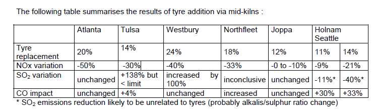
9.10.1. Atlanta experience
The first trial at Atlanta took place in December 1997. The aim of the trial was to replace main burner
fuel by 20%, this equated to one tyre per kiln revolution. The tyre insertion point was located at 55% of
kiln length this was further up the kiln than previously used at Northfleet (38%). The reason for the
difference was that Northfleet had suffered problems with SO2 emissions. The fuel consumption
increased by 40-45 Kcals/KKg resulting in only 75% heat recovery from the tires. The CO emissions
increased and spiked every time a tyre was inserted. The back end Oxygen had to be increased to
3% in order to minimise the CO levels however the CO still remained at unacceptable levels.
The second trial took place October and November 1998. The main difference was the re-positioning
of the tyre insertion chute, moved from 55% of kiln length to 37.5% of kiln length. Moving the gate had
a dramatic effect not only on the CO but also on the kiln operation. The kiln appeared to run more
stable than with coal alone. In addition a higher than average free lime was more readily maintained
with tyres on than with them off. At one point the kiln was running with only 3.5 tph of coal at 80 tph of
fresh feed compared to the normal fuel consumption of 5.5 tph of coal. Although the theoretical
replacement was calculated at 22% the actual replacement seemed higher at 30%. The tire trial
demonstrated that a 20% theoretical fuel replacement could be achieved by using 20 lb tyres at 1 tire
per kiln revolution without any significant increases in CO and SO2 with a decrease of around 49.7%
in NOX emissions.
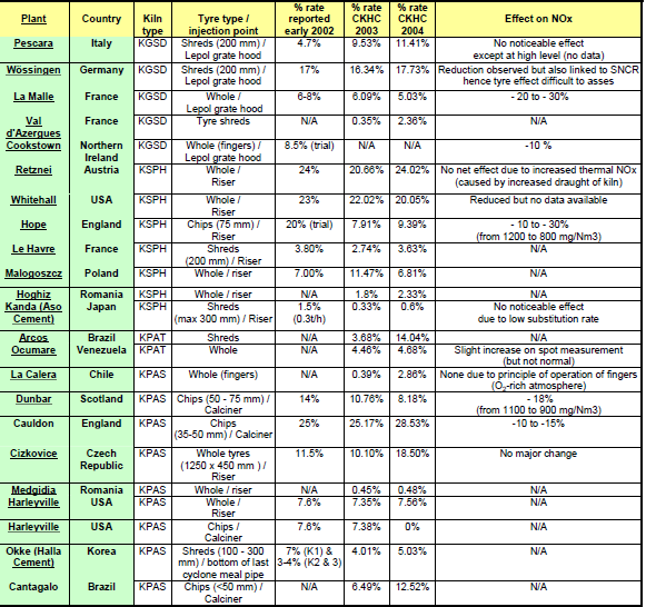
9.10.2. Westbury experience
The trials took place from March 22nd 1999 and concluded on November 10th 1999. 12 individual
extractive measurements for NOx were carried out in both the Tire burning and Baseline periods.
Averaging all the test data shows a reduction in emission of NOx expressed as Nitrogen Dioxide of
41% for tyre burning when compared to baseline (1102 mg(NO2)/m3 compared to 1862
mg(NO2)/m3).One measurement of 1755 mg(NO2)/m3 measured during the tyre trial differs
significantly from the mean and if this was excluded the reduction in emission would be 44%.
There is some evidence to show that the reduction in NOx emission is greater when commercial tyres
are used either in conjunction with car tyres or individually, with emission values below 900
mg(NO2)/m3 being recorded for these tests (more than 50% reduction compared to baseline).
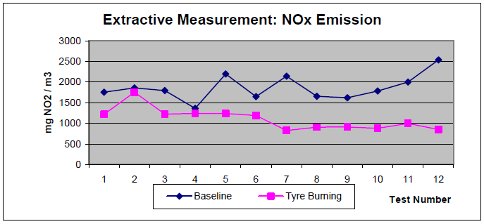
Continuous measurement
For comparison, the average Oxides of Nitrogen emission for the test period as recorded by the plant
Procal continuous monitor is shown (not corrected to reference conditions). It can be seen that the
Procal continuous monitoring data for NOx is in good agreement with the test results.
9.10.3. Northfleet experience
Northfleet cement works has two long semi-wet kilns in operation. Kiln No.2 was lit on August 5th
following a major repair that included the installation of the tire burning equipment. Detailed baseline
emissions testing for the kiln was carried out over the next week. The first tyres were fed into the kiln
on 12th August at 8.30 a.m. The initial feed rate was one tyre per revolution. This equates to a fired
fuel replacement rate of approximately 3.6%. The maximum planned addition rate was five tyres per
revolution or 18% fired fuel replacement.
The most significant changes were a fall in NOX of about 20% and an increase in both CO and SO2.
Other changes included a rise in the back-end temperature of the kiln from approximately 340ºC to
390ºC. This was coupled with an increase in back-end oxygen from 2.4% at baseline conditions to
2.9% in order to assist with the combustion of tyres further towards the rear of the kiln.
The trial has demonstrated that most of the effects predicted from the use of tyres as a fuel at other
works have also applied at Northfleet. A summary is listed below:
• NOX levels have fallen from 1500 ppm at baseline conditions to 1000 ppm at the maximum
addition rate
• SO2 levels have increased at times through the trial but the reasons for this happening at
Northfleet in particular are thought to be well understood. Levels at the time of writing were no
higher than those at the baseline date, i.e. 400 – 500 mg/Nm³
• Back-end oxygen levels have increased, from 2.5 to 3.0%, to assist with the combustion of
tyres and this has resulted in a higher back-end temperature by some 40 to 50ºC. This, in
turn, has meant that a small fuel penalty of 30-40 kcal/kg clinker is incurred.
• CO concentrations have increased from a baseline level of 30 mg/Nm³ up to a level of about
100 mg/Nm³. Like SO2 levels the amount of CO in the kiln is affected by the back-end oxygen.
9.10.4. Joppa results
In 2004, Joppa received its permit to install the Tire Injection System. The initial tests took place in
March and April on Kiln 2. The injectors have been installed at 66.5 m from the discharge on K1 or
39.6% and 66.8 m from the discharge on K2 or 40.6%.
Summary of results documented so far with a replacement of 12% using truck tires:
• NOX levels have been reduced slightly, from 500 ppm at baseline conditions to 450-500 ppm,
giving a 0 to 10% reduction
• SO2 levels have remained at very low levels, going from 30 ppm to 30-35 ppm.
• CO concentrations have slightly increased from a baseline level of 100 ppm to a level of about
100-120 ppm.
• The chain gas temperature has increased from 970 to 1030ºC.
9.11. Mid-kiln tyre injection (non-Lafarge)
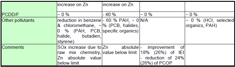
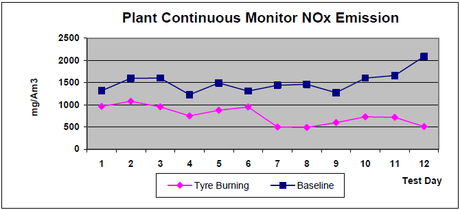
9.11.1. “Holnam” Seattle results
In December 1991, EPA produced the report “Burning Tires for Fuel and Tire Pyrolysis: Air
Implications”, EPA-450/3-91-024 where a chart was published showing air emission results at 11 and
14% substutition :
Summary of the results published with replacements of 11 and 14%:
• NOX levels have been reduced respectively 9 and 21%
• SO2 levels have been reduced respectively 11 and 40%
• CO levels have increased respectively 30 and 33%
9.11.2. US EPA Document
In 1994, EPA produced the report “Alternative Control Techniques Document: NOx emissions from
cement manufacturing”, EPA-453/R3-94-004 where the following table appeared:
9.12. Paulding trials with limestone, steel slag & bottom ash via dust scoops
The Phase I Trials took place in September and October 2002.
Limestone Addition Summary
Limestone was added for 14 days through the dust scoops on kiln 2. It increased kiln production by
5.1%.
Steel Slag Summary
Steel slag was added for 7 days through the dust scoops on kiln 2. The steel slag addition rate was
limited by its high Fe2O3 content (28%) and it increased kiln production by 2.1%.
Bottom Ash Summary
Bottom ash was added for 24 hours through the dust scoops on kiln 2. The bottom ash trial did not go
smoothly due to material handling issues. The bottom ash was difficult to process through the system.
The bottom ash trial was too short to completely assess the effects on kiln operation, but increased
kiln production by 5.7%.
Results on NOx emissions during the tests:
9.13. Picture of Mixing Air Fan (MAF)
9.14. SNCR operation details
In practice all reactions will happen in parallel, but we need to promote the reaction 3 by giving enough
time (point of injection) + temperature (point of injection) + promotion of mass transfer (injection
system: atomization/distribution). In order to limit the secondary emissions (NH3, detached plume
formation…) it is recommended to stay below a molar ratio (NH3/NO) of 1.
Operational layout
For application of liquid reagent the facility contains an unloading station, a storage tank, a conveying
pipeline system including all pumps, fittings, instrumentation, control system (plus connection to the
main control-room) and an injection equipment with some preferably two-component injection nozzles.
All facilities have to respect safety demands.
Therefore in a concept for SNCR the following major points have to be kept in mind:
Flexibility:
– Using materials for several reagents (ammonia, urea)
Safety ↔ Flexibility:
-physical and chemical properties
– health and environmental hazards
– protective measures and instructions
– fire fighting and accidental release measures
– first aid measures
Operational Reliability
-Redundant design (pumps, filters, instrumentation..)
– Tank Size (logistics)
– Insulation + heating (to avoid precipitation, vaporization)
– Concept to avoid coating (e.g.: purge air, big blasters)
Minimum Operational Costs
-Fast reacting control system (a high peak can significantly increase e.g. the half hourly average
emission value)
– Distribution of reagent in „reactor“ = riser duct, hot chamber (arrangement of the atomization
nozzles)
– Consumption of pressurized air
– Low NH3 slip
In case of a solid reagent the idea of the above given list is valid as well, off course taking into
consideration partly different equipment.
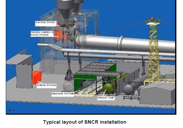
9.15. SNCR experience in CTEC region
The current version of this paper is available in the EASI Technical Centres database under the
following title : “CTEC Technical Info Paper: Selective Non Catalytic Reduction of NOx
emissions”, May 2004“, CTEC, W. Kurka, K. Ladenhaufen, H. Reiterer.
An update of the review of the SNCR systems in CTEC region (including Cizkovice, Sötenich &
Mannersdorf more recent systems) will be available in the future.
9.16. Sugar Creek SNCR trial report by Polysius
9.17. Davenport SNCR trial report by FLS
9.18. Woodstock trials with urea injection via dust
scoops
In 2003, the Woodstock plant made some mid-kiln urea injection tests. There are two wet process
kilns at the Woodstock Plant and both kilns use electrostatic precipitator. Screw conveyors convey the
collected dust to a bucket elevator which deposits the dust in a shroud attached to the kiln. Each kiln
is equipped with a set of ‘three’ dust scoops located approximately one third down the length of the
kiln. It is important to note that the Kiln 2 dust scoops are located closer to the burning zone than the Kiln 1 dust scoops.
Three trials were completed. The following graphs show the impact on NOx during trials on K1 and
K2. The Secondary Air Temperature is also shown as a way to determine if the burning zone was
remaining relatively constant during the trial.
For Kiln 1, the impact of urea on NOx appears to be less conclusive. For Kiln 2, it appears that urea
had a significant impact on NOx.
K1 trial started at 61 minutes adding 40 kg/hr of urea, increasing to 80 kg/hr at 91 minutes and lasting
another 28 minutes.
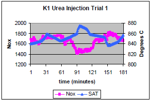
K2 trial started at 51 minutes adding 40 kg/hr of urea, increasing to 80 kg/hr at 76 minutes and lasting
another 25 minutes.
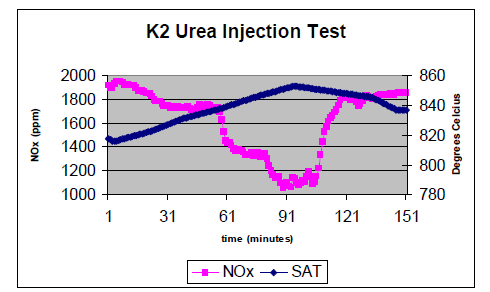
9.19. Holcim Lumbres plant trials with urea injection via rotating seal (long dry kiln)