Mechanical Training Preheater | one from most important articles on the internet|
GENERAL OVERVIEW
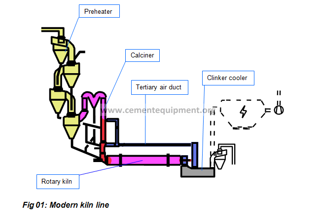
The today’s cement manufacturing process places high demands on a kiln line. Apart from the rotary kiln, modern kiln lines include a multi-stage cyclone preheater and a calciner with tertiary air duct (see Fig 01). The heat produced by the burning process in the rotary kiln and calciner is utilized for preheating the raw material. Preheating and extensive precalcination of the raw material shorten the burning process. The high degree of heat utilization reduces the fuel consumption and the capital cost of the rotary kiln.
CYCLONE TYPES
Preheaters with integrated calciners have three different types of cyclones. The topmost stage has one or more meal-collection cyclones (C-type). The intermediate preheater stages consist of system cyclones (B-type). The lowest stage, which is connected to the calciner, is a calciner cyclone (A-type).
Each cyclone stage basically performs the following two functions:
- It heats up the raw meal in the gas stream
- It separates, the raw meal and discharges it via the meal chute
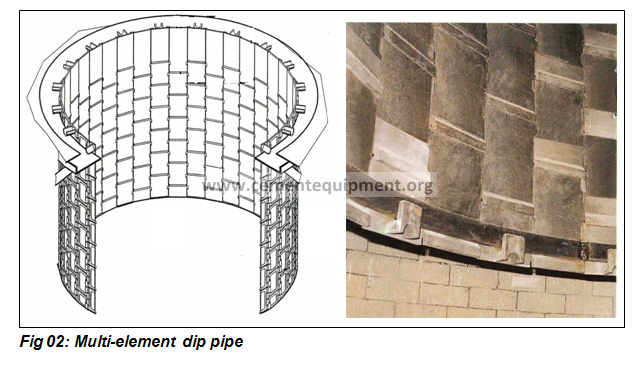
In every cyclone’s head there is placed a multi-element dip pipe, as shown in the following picture. The interior of every cyclone is also provided with a refractory lining.
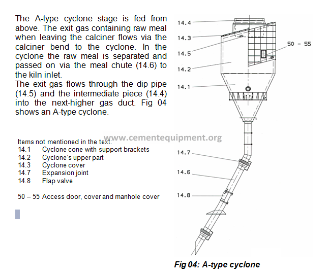
A-Type Cyclone Stage
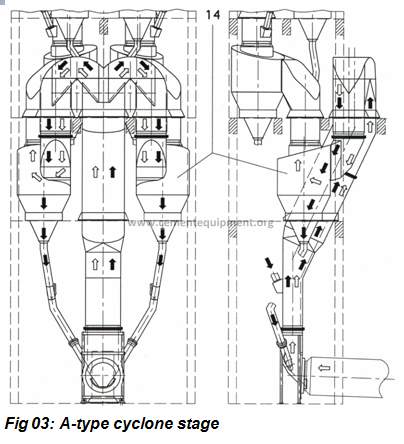
The A-type cyclone stage is arranged in the DOPOL 90 preheater between the calciner and the B-type cyclone stage. The following Fig 03 shows an A-type cyclone stage (14) that is installed in a two-string DOPOL 90 preheater.
Fig 03 also shows the gas steam (white arrows) and the raw meal stream (black arrows).
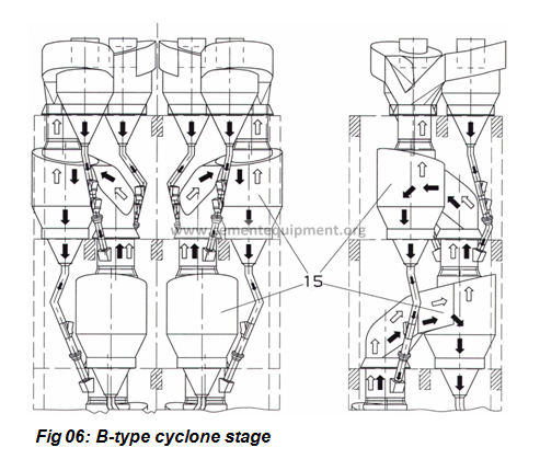
B-Type Cyclone Stage
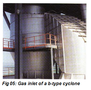
Fig 05 shows a gas inlet of a B-type cyclone (also called system cyclone). One or more of the B-type cyclone stage(s) is/are installed in the DOPOL 90 preheater between the A-type cyclone stage and the C-type cyclone stage, as shown in Fig 06. The following diagram shows a B-type cyclone stage (15) that is installed in a two-string DOPOL 90 preheater.
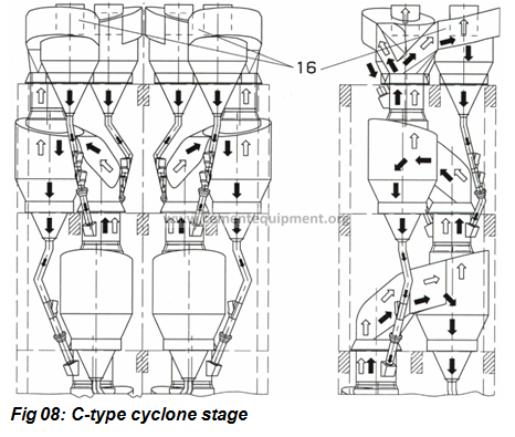
C-Type Cyclone Stage
The C-type cyclone (16) is the last stage (as shown in Fig 08) in the DOPOL 90 preheater. This cyclone stage may consist of one of more cyclones per string. The number of cyclones depends on the throughput of the respective preheater.
HOT MEAL FLAP VALVE
The hot meal flap valves (see Fig 10), installed in the meal chutes, with refractory lining have been specially developed for use in the lower cyclone stages. They prevent the gas from flowing through these chutes and “bypassing” the proper routes.
Hot meal flap valves are discharge devices for a varying mass flow of material with simultaneous shutting-off of the counterflowing hot gas. The exposed cross-section, which remains when the flap blade (3) is closed, corresponds approximately to the filling level at nominal power of the plant.
With increased mass flow of material the flap blade opens. Then the flap blade closes again by means of the external sliding weight (4.1) up to the internal stop. The smooth-running roller bearings (5) of the flap blade do not fail even with possible deformation owing to the effect of heat on the housing.

TERTIARY AIR DUCT
The function of the tertiary air duct in the kiln line is to supply the calciner with additional combustion air. This additional combustion air is hot exit air from the kiln hood or from the cooler.
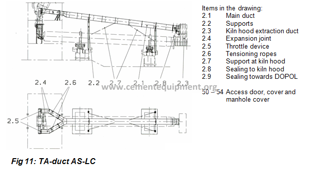
Tertiary Air Duct AS-LC (Air Separate)
The tertiary air duct AS (see Fig 11) with extraction from kiln hood is routed above the rotary kiln from the kiln hood to the calciner and supplies the required combustion air to the calciner burners
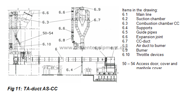
Tertiary Air Duct AS-CC (Air Separate – Combustion Chamber)
The tertiary air duct AS-CC (see Fig 12) with cooler exhaust is running along the kiln from the clinker cooler to the combustion chamber CC (6.3) and it supplies the burner aligned in the ceiling of the combustion chamber CC with the combustion air required. The raw meal discharged from the second lowest cyclone stage and also the fuels are fed into the combustion chamber CC. The combustion chamber CC is connected to the transition piece AS-CC. The exhaust gas flows from the combustion chamber into the calciner via the transition piece AS-CC. The raw meal is separated in the combustion chamber CC and it fed to the transition piece AS-CC via the meal chute.
Here, the dispersing box ensures an even distribution of the raw meal in the transition piece AS-CC.
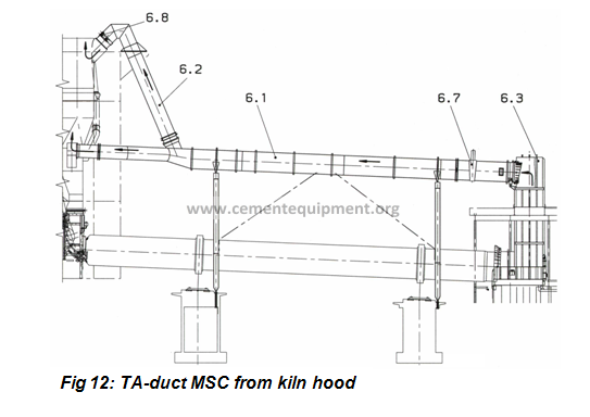
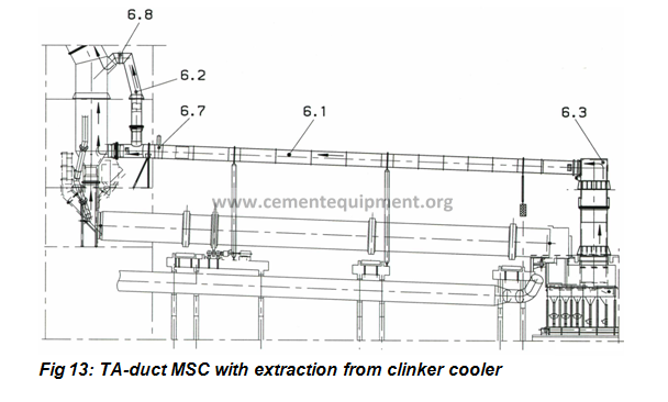
Tertiary Air Duct MSC (Multi Stage Combustion)
The tertiary air duct MSC begins with the suction chamber (6.3) and then runs parallel to the precalciner. The tertiary airflow through the main duct (6.1) and through the head duct (6.2), which provides a two-stage combustion at two levels in the calciner.
The throttle devices (6.7) and (6.8) effect the air distribution.
The TA-MSC duct is available in two variations. Fig 12 shows the TA MSC duct connected to the kiln hood. Another variation is the connection of the duct to the clinker cooler, as visible in Fig 13
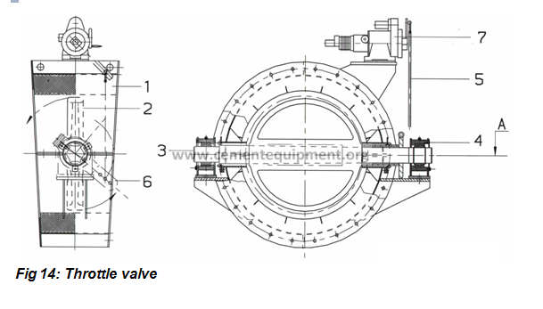
THROTTLE VALVE IN THE TERTIARY AIR DUCT
The throttle valve (see Fig 14) with refractory lining has been specially developed for use in the tertiary air ducts. It reduces the flow rate of the tertiary air to the set value required to ensure optimal burning in the rotary kiln and in the precalciner. The valve consists of the housing (1), the valve blade (2), shaft (3), bearings(4), linkage (5), operating lever (6) and the actuator (7).
CALCINER TYPES
Calcination is the decomposition of the CaCO3 contained in the cement raw material, producing CaO and CO2. This part of the burning process takes place in the calciner, before the raw material is sintered in the rotary kiln.
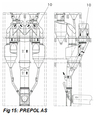
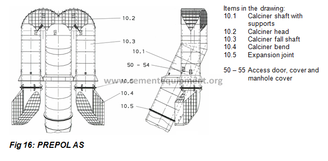
PREPOL AS (Air Separate)
The calciner (see Fig 15 and 16) is installed in the kiln line between the kiln inlet and the lowest cyclone stage at the preheater. All parts of the calciner are equipped with access ports and poke holes for inspection work. It is also equipped with inside refractory lining.
The raw meal is fed in the transition piece, the fuel and the tertiary air are conveyed together with exhaust gas through the calciner to the cyclone of the lowest stage (A-type). Fig 15 shows the exhaust gas – and tertiary air streams (white arrows) and the raw meal flow (black arrows). Exhaust gas, tertiary air and raw meal are flowing in co-current flow.
In the calciner, the raw meal is heated by heat exchange.
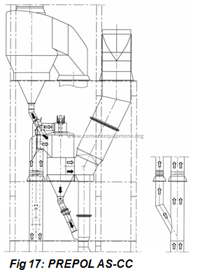
PREPOL AS-CC (Air Separate – Combustion Chamber)
In many components similar to PREPOL AS, the PREPOL AS-CC is equipped with a additional combustion chamber. This chamber is positioned between the second cyclone stage and the calciner, as visible in Fig 17.
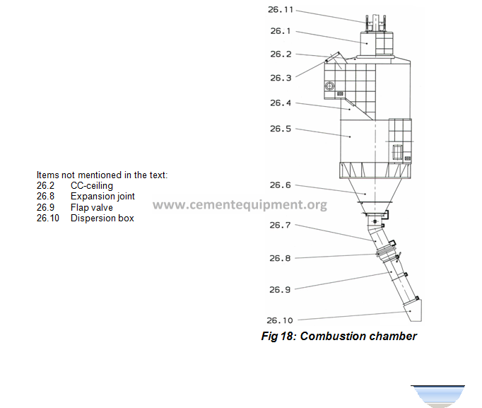
The combustion chamber (see Fig 18) has the following functions:
- to provide process heat for the calciner;
- to create a high-temperature zone for accelerating the combustion of fuels with low reactivity.
The CC-burner (26.11) is positioned on the CC-head (26.1) centrally to the combustion chamber. A small part of the combustion air (tertiary air) in introduced into the combustion chamber through the CC-head (26.1) and the major part of the combustion air enters the CC-section (26.4) tangentially.
The actual combustion is initiated in the center of the upper CC-section (26.4) where the dust content is low. To protect the inner walls of the combustion chamber, a raw meal veil is generated by the special arrangement of the meal feed socket (26.3) in the tangential current.
The gases and a part of the raw meal enter the calciner via the middle CC-section (26.5) while the remaining part of the raw meal enters the calciner via the CC-meal chute (26.7)
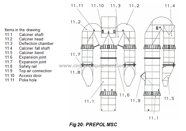
PREPOL MSC (Multi Stage Combustion)
The MSC Calciner (see Fig 19 and 20) reduces emissions by staggered introduction of the fuel, tertiary air and raw meal, which causes combustion to take place in several stages. In the first stage, the nitrogen oxides generated in the sintering zone of the rotary kiln are reduced by means of a burner in the kiln inlet. In order to prevent new NOx from being generated in the calciner, the calcining fuel has also to be burnt. This is achieved by staggered introduction of the combustion air, so that the fuel is first burnt under reducing conditions and then under oxidizing conditions.
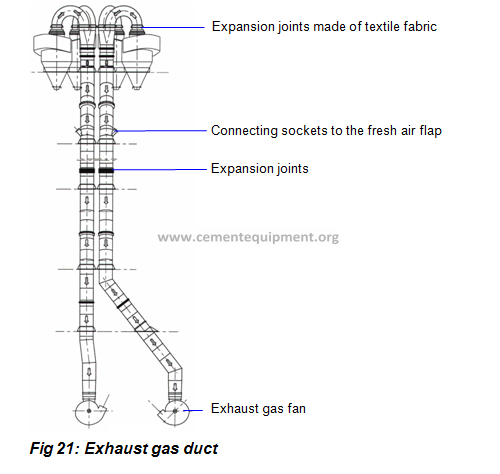
EXHAUST GAS DUCT
The exhaust gas duct connects the last cyclone stage (Type C) of the preheater either with the evaporate cooler or with the exhaust gas fan. The white arrows in the following Fig 21 show the exhaust gas stream directly to the exhaust gas fan (without evaporative cooler).
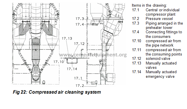
COMPRESSED AIR CLEANING SYSTEM
The DOPOL preheaters are equipped with an automatic compressed-air cleaning system (see Fig 22). In preset intervals, particularly critical points are blown through as a precautionary measure. This helps to prevent the formation of caking or the settling of deposits. Fig 22 the compressed-air cleaning system (17) including a compressor (17.1) that is installed in a two-string DOPOL preheater. The solenoid valve control system controls the blowing and the „off” periods of the compressed air cleaning system in adjustable intervals. You are advised to change the cycle times that were set during the commissioning phase, only after having operated the plant with the initial setting for a longer period of time. It is also possible to control the compressed-air cleaning system by hand. The compressed-air cleaning system is usually operated at a pressure of 7 bar.
If the pressure falls below 4 bar, a fault indication will be triggered.
The first air blasts are always directed into the lower sections of the preheater. The space thus blown free will serve to collect any sliding-down material blown off in sections arranged further up.
Via permanently installed connections in the relevant points it is possible to connect additional blowing lances with the compressed-air cleaning system. The blowing lances and the pertaining hose lines and coupling sections are provided in different lengths and included in the scope of supply. It is thus possible to blow additional compressed air into the preheater system through the cleaning ports of the cyclones, the dispersing boxes and the meal chutes
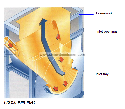
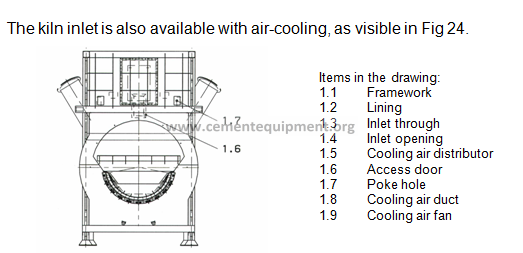
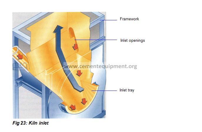
KILN INLET
The kiln inlet (see Fig 23) connects the tilted rotary kiln to the calciner or to the gas duct of the preheater. The interior of the inlet is provided with a refractory lining.
Coming from the rotary kiln, exhaust gas flows through the kiln inlet to the preheater (blue arrow). The raw meal enters the inlet via the meal chutes and passes through the kiln inlet downward to the rotary kiln (red arrows). Exhaust gas and raw meal pass in counter flow. Raw meal streams merge enter simultaneously in the kiln inlet. These two raw meal streams merge only shortly before entering the rotary kiln. Thereby turbulences of dust are prevented to a large extend.