Contents
KILN STABILITY
[wpecpp name=”package + Updates forever” price=”250″ align=”center”]
KILN STABILITY REQUIREMENTS
This paper outlines the nuts and bolts of kiln mechanical stability.
There are six areas of mechanical interaction on a rotating kiln.
1. The tire and support roller interaction
2. The tire ID and shell interaction
3. The roller shaft and bearing liner interface
4. The roller bearing thrust mechanism
5. The thrust roller and tire interface
6. The pinion and main gear interaction
TIRE AND ROLLER INTERACTION
The mechanical stability of the tire to roller interaction requires that the roller axis
and the kiln rotation axis be parallel. The direction of motion of a rotating object
is perpendicular to its axis. If the roller and kiln axis are not parallel, the direction
of motion of the two components will not be along the same line. In other words,
the motion of the tire relative to the roller will have a horizontal component. This
condition causes the kiln to move uphill or downhill and the roller to move in the
opposite direction. If the horizontal motion component is high, the roller bearing
thrust mechanism overheats from high pressure, and the load on the kiln thrust
roller may be high. Correcting this condition requires the adjustment of one of the
roller bearings such that the direction of motion of the kiln and the roller become
identical.
Lubricating the tire-roller interface with graphite will decrease the roller thrust
load, and will decrease the pressure on the bearing thrust mechanism. This is
because the source of the thrust load is traction in the horizontal direction
between the tire and the roller. The graphite lubricant decreases the traction by
reducing the coefficient of friction between the tire and the roller. Note: If a
bearing overheats and the cause of the high temperature is high roller thrust
load, lubricating the roller face will quickly reduce the bearing temperature.
TIRE AND SHELL INTERACTION
The tire ID is larger than the shell OD. As the kiln rotates, there is circumferential
displacement between the tire and the shell as a result. This motion is commonly
referred to as tire creep. If the plane of the tire is not perpendicular to the rotating
axis of the shell, the direction of motion of the shell is slightly different than the
direction of motion of the tire. The tire moves uphill or downhill as a result, until it
hits the tire retainers. On other words, the tire creep has a horizontal component.
If the angle between the tire plane and the shell is not between 89.5 and 90.5
degrees, the pressure on the tire retainers will be high. Furthermore, since the
tire retainer pressure comes from the interaction between the tire ID and the
support pads, the rate of wear of the support pads (due to slippage in the
horizontal direction) will be high.
There are two mechanisms that tilt the tire plane relative to the shell axis:
a) A taper condition on the tire or the support rollers
b) Support roller slopes.
Correcting a high stop block load condition therefore requires either the
resurfacing of the tire and the rollers or changing the support roller slopes.
Since the tire retainer pressure is caused by a motion component between the
tire and the shell, the pressure is directly proportional to the tire creep, and
therefore to the tire clearance. Decreasing the tire clearance by 50% (by
shimming or replacing the support pads) will decrease the tire retainer pressure
by 50%.
The source of the force causing retainer pressure is traction between the tire ID
and the shell. If the tire ID is lubricated, the coefficient of friction between the tire
and the shell will decrease, and the tire retainer pressure will also decrease. The
most effective lubricant for this application consists of soft metal powders
dispersed in a carrier that evaporates. The source for the lubricant with the
highest solid content is www.anioncorp.com. The lubricant is available in the
form of wax bars or a sprayable liquid. The sprayable form prevents the close
proximity to moving parts that is required to install the wax bars between support
pads. Please note that graphite is a very ineffective lubricant for this application.
It does not laminate onto the tire ID, and is very easily dislodged from the
surfaces it is supposed to lubricate.
Bearing adjustments are commonly made with the intention of decreasing tire
retainer pressure. It is mistakenly believed that if, for example, the downhill stop
blocks on a pier are overloaded, the pressure can be decreased by adjusting the
support rollers to push the tire uphill. This attempt to fix the problem rests on a
lack of understanding of the relationship between two independent sets of forces
effecting mechanical stability at each pier. The horizontal motion component
between the tire and the roller affects the axial motion of the entire kiln, but will
not affect the position of the tire relative to the stop blocks. Stop block pressure
is a function of the horizontal motion component between the tire ID and the
shell; this motion component is independent of the tire to roller interaction. (For
the record, the previous statement is not an absolute truth. Very extreme bearing
adjustments, with one roller pushing uphill and the other downhill, will tilt the tire
plane relative to the kiln axis, and will thus affect the tire retainer pressure. The
magnitude of bearing adjustment required to do this, however, is so extreme that
it results in the overload of the support roller bearing thrust mechanism. While
this procedure can be beneficial as a short term fix, it does not work in the long
term).
ROLLER SHAFT TO BEARING LINER INTERFACE
The interaction between a roller shaft and a bearing liner will generate high
temperature leading to bearing failure unless certain stability conditions are met.
The diameter of the brass liner has to be 0.002” greater than the shaft diameter
for every inch of shaft diameter. In other words, a 20” shaft has to have a liner
with a 20.040” diameter. If this condition is not met, there will not be enough
lubricant between the shaft and the liner, and bearing failure can occur.
The viscosity of the bearing lubricant is very important. There are no advantages
to using low viscosity oils, i.e., ISO 680 or lower. There are however important
advantages to using heavy oils. The viscosity of 680 oil is only about 120 cst at
200 degrees F. In other words, the oil viscosity drops by about 80% when the oil
temperature increases by 100 degrees. If the room temperature viscosity of an
oil is 3200, that oil will have sufficient viscosity to lubricate a bearing at up to 350
degrees, (a temperature at which a 680 oil will fail). If oil viscosity is adequate at
an elevated temperature, a bearing will remain stable at that elevated
temperature. Since bearing temperatures can rise for a variety of reasons, it is
prudent to use the highest viscosity oil, (consistent with the pour point
requirements dictated by weather conditions at plant site). The lowest reliable oil
viscosity for kiln bearing application is ISO 1500.
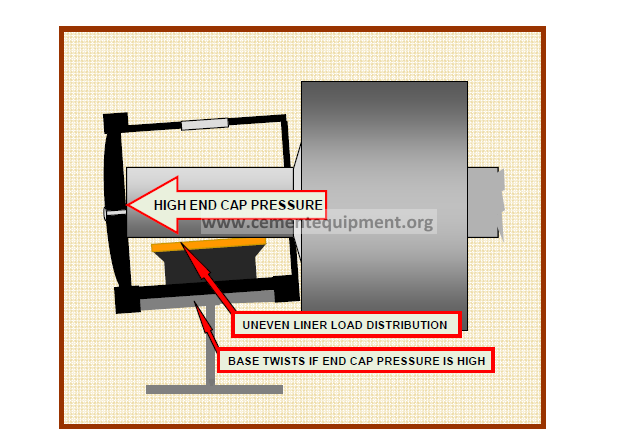
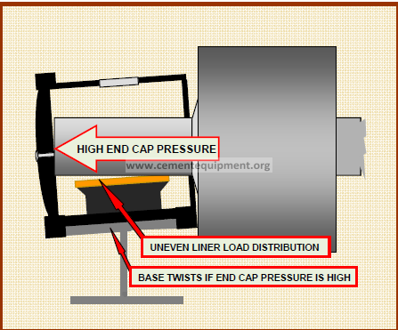
The uphill and downhill bearings have to be in line to insure uniform and low
bearing pressures on both liners. This requirement is often unmet because the
bases under the bearings are twisted. If the uphill and downhill bearing base
pedestals are not in the same plane, the two brass liners of a roller will not be in
line. The bearing liner load distribution will then be uneven. At the position of
maximum bearing liner load the bearing pressure may be excessive and the
lubricant viscosity may be inadequate for the pressure. This condition often
occurs with bearings that use end caps to contain thrust loads (i.e. Fuller and AC
bearings). If an end cap pressure is high enough, the bearing places a sufficient
torque on the base plate to twist it. The base edge at the end cap bends down
and the bearing tilts in the direction of the bent base plate. As the bearing
housing tilts, uniform liner load distribution is lost. Base installations and base
repairs must be done consistent with the requirement for uniform brass liner load
distribution. Note that if a base plate is twisted, a high viscosity oil is less likely to
fail (as a result of areas of high bearing pressures) than a light oil.
BEARING THRUST MECHANISM LOADS
The thrust load on a support roller moves the roller along a line parallel to the
kiln axis. The motion of the roller is stopped by a thrust mechanism in one of the
bearings. There are two types of bearing thrust mechanisms: a) a heavy bearing
housing end plate that contacts the end of the roller shaft and b) a thrust collar or
flange on a roller shaft that contacts a flange on the bearing liner. If the thrust
load on the roller is high enough, the pressure per square inch on the loaded
thrust mechanism will be excessive, resulting in a) lubricant breakdown and
bearing failure or b) structural failure of the thrust wear plate. Measuring and
minimizing the thrust load on a support roller can prevent these undesirable
consequences. Measuring the bearing thrust pressures and making the proper
bearing adjustments should be part of the scope of work of a comprehensive hot
kiln alignment. The pressure on the thrust mechanism has to be under 300 psi to
assure reliable stability.
TIRE/THRUST ROLLER INTERFACE
The axial motion of the kiln is limited by thrust rollers. The position of the thrust
rollers relative to the tire should be 1/16” off the six o’clock position of the tire,
away from the drive pinion side of the kiln.
The direction of motion of a rotating thrust tire at any point on the tire
circumference is parallel to the tangent to the tire at that point. At the six o’clock
position, the direction of motion of the tire is horizontal. Slightly away from the six
o’clock position, the direction of motion has a vertical component; the tire moves
up or down, in addition to moving horizontally. A vertical motion component at
the point of contact between the tire and the trust roller will push the thrust roller
down, or lift it up. The resulting friction will wear the thrust roller and the tire.
If a tire pushes a misaligned thrust roller down, vertical load builds up. As the tire
moves off the thrust roller the vertical load is relieved and there is vertical
slippage between the tire and the roller in the process. In time, this vertical
movement creates a slight flat spot on the tire and the thrust roller. These flat
spots serve as surface discontinuities, where future vertical thrust loads are
relieved. Over time the sizes of the flat spots increase, making the thrust roller
unusable. Flat spots on the side of the thrust tire can serve as a source for kiln
vibrations.
If a thrust roller is not properly aligned relative to the six o’clock position of the
tire, there is a danger of lifting the thrust roller shaft out of its bearing housing,
and hitting the tire stop blocks. The load capacity of the roller shaft is significantly
diminished if it lifts out of the bearing housing. Most thrust roller shaft failures
occur by way of this mechanism.
The lubricant in the thrust roller bearings should be ISO 3200 grade. Since oil
circulation is not a consideration, the high pour point of the oil is immaterial. The
high viscosity of the 3200 oil provides significant separation between the shaft
and the brass liner.
PINION AND MAIN GEAR INTERACTION
The smooth transfer of load from the driving pinion tooth to the following tooth is
assured by having two adjacent teeth share the load for a period of time. Tooth A
carries the load; tooth B is engaged before tooth A disengages. This load
overlap requires that the gear set have the proper root clearance. In other words,
if the pinion is set too far out of mesh, the load overlap will be lost. This condition
is very typical. As part of the pinion alignment procedure, the pitch lines are
usually set apart, in anticipation of a decrease in root clearance as the kiln heats
up. Counterintuitive as it may seem, the gears actually separate as a result of
thermal expansion. As the kiln diameter expands, the 12 o’clock position of the
gear moves up however much the diameter increases; the 6 o’clock position of
the shell does not change; the shell axis moves up one half the shell diameter
increase. Since the gear is centered on the shell axis, it is lifted out of mesh
when the shell axis elevation increases. When setting the pinion on a gear set,
the pitch lines should overlap 1/16”. As the kiln heats up, the pitch lines will
separate via the above thermal mechanism, but the overlap of the gear set will
remain adequate.
Proper analysis of problems pertaining to kiln stability requires in
depth knowledge of the variables involved. If the above information
is something you have not seen before, you need NAK as your kiln
service provider. Please contact NAK for reliable solutions to all kiln
related problems. We are your best source for rotary kiln technical
information that makes sense.