Kiln maintenance: unnecessary expense or profit generator?
to Download the Book of KPI in cement Industry and more than 25 expert books in cement industry kindly click here
Kiln Maintenance: unnecessary expense or profit generator?
It may be argued that the expense of modern kiln maintenance procedures is quickly returned in profit increases
Rising energy costs, increasing labor costs, and lost production through equipment failure are serious problems that cement manufacturers are facing as they struggle to survive in today’s competitive markets. These three maintenance-related areas seem to be some of the few avenues open to control the upward spiral of today’s operating costs. Efficiently planned and executed maintenance schedules cannot only reduce operating costs but can also directly influence profit margins.
However, many cement plants are reluctant to spend money on kiln maintenance. The issue that faces today’s plant manager is this: Is planned kiln maintenance just an operating expense that can be postponed if the budget is tight or should it be perceived as an investment that can increase the profitability of a company?
This article will illustrate how some cement plants have used two basic kiln maintenance procedures to decrease operating costs and reduce energy usage, while increasing production levels and profit margins. These kiln maintenance procedures are tyre and support roller resurfacing and in-production mechanical analysis (‘hot kiln’ alignments). Before describing three case studies that illustrate how these procedures impact profitability, some basic kiln-related terminology and concepts will be discussed.
Concave and convex wear
Concave and convex wear is a common occurrence on the surfaces of tyres and support rollers. As pictured in Figure 1, concave wear is typical on the support rollers and convex wear is more prevalent on the tyre. The wear develops when support rollers are over-skewed to control the axial thrust of the kiln. The severity of wear is proportional to kiln loads and environmental contamination near and around the rolling surfaces. Severe cases of convex and concave wear can develop which will significantly restrict the travel of the tyre as the kiln changes its direction of axial thrust. When certain conditions exist, it is possible to damage thrust collars, thrust plates and other related components of the bearing housing assemblies. Since the actual load surface of the tyre and rollers is reduced, wear will accelerate and greater bearing adjustments will be necessary to control the axial thrust of the kiln. This will result in a significant frictional drag between the bearings and the roller shaft that will increase loading on the kiln drive system.
Uneven wear
As shown in Figure 2, uneven wear is usually caused by product or dust contamination passing through the contact point of the tyres and support rollers. This type of wear can also develop when rollers run in product build-up in the pits of the support roller structural bases. Severe uneven wear causes a poor transition surface for the tyre and support rollers which will hinder the axial movement of the tyre. This wear condition generates a frictional drag on the kiln drive system and can cause high contact pressures on the rolling surfaces if sufficient wear exists.
Tapered or conical wear
Radial taper on the surfaces of the tyres and/or the support rollers is one of the most difficult types of wear to detect. One noticeable indication of this wear condition is the axial loading of the tyre against the retaining bands/blocks. Tapered wear is an undesirable condition because the tyre will move toward the loaded side of the contact surface. Figure 3 shows an example of conical wear. A taper on the tyre or roller will generate wear on the support pads and tyre ID and will make support roller adjustments difficult. The wear on the support pads and tyre ID will accentuate the gap between tyre and shell, subsequently increasing the percentage of shell ovality. When this wear condition exists, there is often a significant amount of roller misadjustment that will increase the frictional drag on the kiln drive system. The inclination of plant personnel is to adjust rollers to close the gaps between tyres and rollers. This method of adjustment will create a misalignment of the roller shafts with the tyre axis generating unequal axial thrust.
Diagonal marks
Diagonal marks are evident when there is incorrect adjustment between the support rollers and the tyre. The support rollers are adjusted so the axis of rotation on each roller is not parallel. Consequently, the tyre does not have a smooth rolling surface and frictional drag results, generating tapered wear on the surfaces of the tyre and support rollers. This condition creates a high torsional load on the shell that hinders the smooth operation of the kiln drive system.
Horizontal marks
Like diagonal marks, horizontal marks develop when the support rollers are incorrectly adjusted and/or misalignment of the drive gear and pinion is present, Figure 6. Although this condition is more common on two-pier higher speed kilns, it can also exist on the large, slower kilns.
Sometimes the misadjustment does not occur between two rollers on the same pier. Misadjustment can be present when rollers on adjacent piers are adjusted to thrust in opposite directions. If this condition is present it will cause rough operation of the drive gear and pinion. Additionally, the torsional loading on the kiln will increase, resulting in a drag in the kiln drive system. The wear conditions are generated by many different circumstances which can not be covered at length in this article. Individually or collectively, these wear patterns will influence the overall efficiency of the kiln drive system and will require a greater allocation of maintenance expenditure and plant labor to effectively operate the kiln.
Tire and support roller resurfacing
Tyre and support roller resurfacing is the process of removing various types of surface wear. The actual grinding process is performed in-place with no production downtime so the work does not interrupt the normal operation of the kiln. As the wear is removed, adjustments are made to the support rollers to locate the roller shafts as close as possible to a neutral thrust position. The removal of this wear and the balancing of the support roller thrust will notably diminish the frictional drag placed on the kiln drive system, in addition to stabilizing the axial thrust of the kiln.
Hot kiln alignment
The method of alignment employed on a kiln, must achieve two fundamental principles. Accurate measurements must be taken when the kiln is in operation to determine pier loading. The operating axis of the kiln shell must be identified and defined in relationship to the slope of the support rollers. A straight shell axis during normal kiln operation will reduce the frictional drag on the drive system, decrease the shell deflection or ovality due to excessive pier loading, and greatly reduce the adjustments needed to control the axial thrust of the kiln. If these three improvements are realized, kiln drive amperage will be reduced, the likelihood of refractory failure will be diminished, and kiln maintenance costs will decrease. Two common kiln alignment variances can affect the straightness and stability of the shell, as well as its operational efficiency.
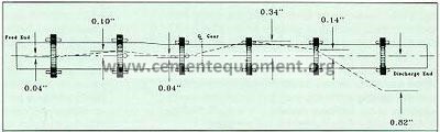
Incorrect elevation axis of the kiln
An incorrect elevation of the kiln axis exists when the kiln shell does not have an axis of rotation that is consistent with the slope of the structural steel bases, as illustrated in Figure 9. Shell slope will not match tyre and roller slope and high axial thrust will be present on the related piers. The tyre will have high axial loads against the retaining blocks/bands if this condition exists. Higher loads will be placed on the bearings which will create higher Hertz pressures on the roller shafts and the bearing liners. Frictional drag will eventually occur between the tyres and rollers causing torsional loading of the shell between the respective piers. Inevitably, the torsional drag will cause a significant increase in the amperage needed to operate the kiln.
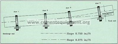
Misalignment of the kiln in elevation is common because of the thermal expansion of the kiln. If the kiln is aligned while it is out of production and cold, consideration must be taken to position the kiln where the axis will be after thermal expansion of the shell, tyre and rollers. This position is difficult to determine because the shell is not uniform in temperature (it is higher in the burning zone than at the feed end). Brick thickness and environmental conditions can make it nearly impossible to prevent elevation misalignment of the kiln shell unless that alignment is performed while the kiln is operating. The elevation alignment affects the kiln drive amperage. Contrasting loads will be placed on the individual support rollers. It is evident in Figure 9 that there will be more loading of the #1 and #4 piers support rollers. Since these support rollers will carry more than their share of the design loads, the Hertz pressures will be higher between the roller shafts and the bearing liners. Consequently, a frictional drag will result between the bearing liners and the support roller shafts, initiating a load on the kiln drive system that will result in higher energy consumption to rotate the kiln. Furthermore, shell ovality will be higher on the loaded piers and for this reason, measuring shell ovality is a necessary function of a hot alignment, (Figure 10, item 2).
Incorrect plan view shell axis
An incorrect plan view axis of the kiln shell will result in loading problems similar to those found with elevation misalignment, with one exception. The vertical slope is not a consideration in the plan view. However, it is interesting to note that the elevation misalignment will influence or heighten the reaction caused by a plan view deviation from the design axis of the kiln. A deviation of the shell axis in the plan view will result in a reaction even if the elevation axis of the shell is correct.
With a plan view misalignment, the axis of the roller shafts will be affected by the plan view axis of the kiln shell. Figure 11 relates the effect of the kiln axis in the plan-view plane as it compares to the axes of the respective roller shafts. This diagram shows a kiln shell with a distinct curve to one side. Notice how the axis of the shell relates to the axis of the respective support rollers. Ovality readings will also demonstrate that one roller on this pier is taking more load than the opposite roller, (Figure 10, item 6). If the discharge end support rollers are adjusted to have full face contact with the tyre, the roller axis will correspond to the axis of the shell. The bearing on the feed side will have a shorter distance to travel to reach the desired axis than the bearings on the downhill side of the tyre. For this reason, it is best to swap the position of each roller shaft intermittently when making alignment moves on the support rollers. Shell alignment as outlined here will cause an unstable condition with the axial thrust of the unit, and again generate greater energy requirements to rotate the kiln.
In addition to the apparent problems created when elevation and plan-view shell misalignments place torsional load on the shell of the kiln, an additional concern is the effect of the torsion on the brick or refractory. The resistance of the kiln shell to rotate because of the tyre and roller wear and a shell misalignment condition puts the shell in high torsional stress, creating an unstable environment for the bricks. Since the installation of refractory brick does not allow for torsional movement, any significant amount of loading may result in premature refractory brick failure. When examining various conditions that will generate a torsional loading of the kiln shell and reduce the energy efficiency of the kiln drive system, it is evident that the following considerations affect the operating kiln.
Wear on the surfaces of the tyres and support rollers will generate high hertz pressures on the contact surfaces, induce frictional drag between the roller shafts and bearing liners and make it difficult to control the axial thrust of the kiln with minor roller adjustments. Kiln misalignment will place a bind on the kiln shell and higher loads on the respective support piers. Minor support roller adjustments will be difficult to perform. Because of component wear and the kiln shell misalignment, the torsional loading of the shell will decrease the energy efficiency of the drive system and generate wear on the drive components. Since the above conditions affect the ability to perform minor support roller adjustments for controlling the axial thrust of the kiln, the rollers will probably be misadjusted. This will create additional wear on the component parts and the amperage required to rotate the kiln will increase. It is important to note that as the energy increases to turn the kiln, the additional energy to overcome the frictional drag creates additional wear on the component parts of the drive system, the tyres, and support rollers. Furthermore, productivity will decline and maintenance requirements of the kiln will increase.
To achieve maximum efficiency of kiln production, it is evident that a hot kiln alignment should be performed in conjunction with the tyre and roller resurfacing. The following case studies of three manufacturing plants substantiate the effectiveness of these two maintenance procedures in increasing productivity and operating efficiency. These advantages are enhanced when one notes that both the resurfacing and alignment procedures can be achieved with no production downtime. Resurfacing and Alignment case studies
Case One: A 6-pier, Allis-Chalmers wet-process cement kiln in the Western United States was not operating to design specifications or production standards. Amperage readings were high and at many times unstable. The refractory brick life of the kiln was unsatisfactory and the brick would seldom last through an annual campaign. Plant personnel were constantly called to make roller adjustments to control the axial thrust of the kiln. The kiln was designed with hydraulic thrust rollers on the downhill side of the middle piers. As the kiln moved uphill, production was halted until adjustments could be made to move the kiln downhill. Production was lost because of frequent kiln outages and maintenance costs were magnified. This was a distressing circumstance as the plant was sold-out and thus sales from lost production could not be regained. In simple terms, they were producing less clinker at a greater operating cost and losing profits from the lost sales.
An inspection of the unit indicated misalignment of the kiln axis and a significant amount of wear on the tyre and support roller surfaces. Further examination revealed that support rollers were adjusted sporadically throughout the length of the kiln shell so that some rollers were pulling the kiln uphill and the remaining rollers were pushing the kiln downhill. The recommended course of action was to repair the worn surfaces of the tyres and support rollers with the resurfacing procedure followed by an in-production mechanical analysis or ‘hot kiln’ alignment.
The resurfacing procedure was performed in conjunction with support roller adjustments to eliminate the volatile thrust condition of the kiln. Adjustments were made to each individual support roller to locate the neutral position of the roller shafts. After these adjustments were achieved, small incremental moves of the bearing housings were made to control the axial thrust of the kiln. After the wear conditions on the tyre and roller surfaces were eliminated and the axial thrust of the kiln was stabilized, the frictional drag on the component parts was significantly diminished.
The next phase of the project was to perform the mechanical analysis or ‘hot kiln’ alignment. The goal of the mechanical analysis was to identify the reason for the inferior brick life and to determine the exact location of the kiln shell operational axis of rotation. Ovality readings were performed and a complete survey of the elevation and plan view position of the kiln shell axis was computer analyzed. Structural steel support bases were measured for actual slope and compared with the actual slope of the support roller shafts. The kiln was found to be out-of-position in the plan view significantly on the discharge pier. In addition, some other alignment discrepancies were apparent.
Arrangements were made to perform support roller adjustments to position the kiln shell at the correct operational axis. The adjustments were made over a period of several weeks to maintain the delicate axial thrust of the kiln and to eliminate any production delays as a result of the process. Both the resurfacing and alignment procedures were completed without any delays in production. Maintenance department participation was held to a minimum.
The results of the combined procedures were excellent. The production of the kiln increased by 25% immediately after the work. Kiln drive amperage has remained an average of 15% lower since the project was completed. The life of the refractory brick increased allowing a full year’s service without kiln-related brick failure. The overall plant efficiency increased by 5%. Support roller adjustments to control the axial thrust of the kiln were virtually eliminated. Effectively, the profits of the plant increased significantly.
Case Two: A 4-pier, F.L Smidth kiln at a plant in Quebec, Canada. Similar misalignment and wear circumstances existed which exhibited operational problems. In this plant there were three other kilns that had similar operating problems as the subject kiln. Control of the axial thrust was difficult, requiring an excessive amount of maintenance manpower. Brick life was inadequate and production output was reduced. All of the product produced at this plant was sold in advance so that any production down time associated with these maintenance problems resulted in lost profits.
After the resurfacing and ‘hot kiln’ alignment procedures were performed, the drive amps on the subject kiln dropped from 190 amps to 150 amps, the daily production increased from 80 tph to 110 tph, and the operating efficiency of the kiln increased to 95%, up from 75%. After realizing these results, plant personnel performed the same maintenance procedures on the three remaining kilns. Similar improvements in amperage, production, and operating efficiency resulted. Company officials saw a phenomenal increase in the operating profits of this plant.
Case Three: A plant in Minnesota, USA, had five large 22 ft. dia., Allis-Chalmers kilns for steel production that had serious operating problems. The drive system had serious frictional drag on the components generating high kiln drive amperages. Numerous hot bearings were causing lost production on a weekly basis, production capacities were unsatisfactory, and plant maintenance on the equipment was extensive. After analyzing the above conditions resurfacing and alignment were recommended and performed.
The results were impressive. The kiln drive amperage dropped from 595 amps to 345 amps on one unit, a 42% decrease. Since the additional amps were being employed in overcoming the frictional drag, a noticeable change was seen in the operating efficiency of the drive system. The hot bearing temperatures on the support rollers were eliminated completely. Consequently, an average of 12 hours per week of lost production on each drum was regained, increasing the productivity of the entire plant. Adjustments to the support rollers were no longer needed and maintenance on the kilns has been reduced to checking the bearings for thrust on a periodic basis. The initial cost of the maintenance work was recovered in a few months of trouble free operation at the design production capacities.
The documented results of the resurfacing and alignment procedures at these three sites clearly speak for themselves. Unfortunately examples can also be cited where the resurfacing and/or alignment procedures were done by in experienced crews and inferior or poorly designed equipment. The success stories like the ones mentioned here all have several things in common:
The technicians performing the work were highly trained and had years of experience in these kiln maintenance techniques.
The equipment used was specially designed and manufactured (and, in these examples, patented).
The procedures used were advanced (also patented), proven reliable, and extremely accurate.
The resurfacing process and the in-production mechanical analysis have been successfully performed in North America for many years. Cement companies in many parts of the world are now utilizing these procedures to assist with the mechanical maintenance of their equipment. Performing these procedures will make kiln maintenance simpler and more effective. That fact makes resurfacing and kiln mechanical analysis worth their cost. These maintenance procedures become more important to cement plants when their effects on company production levels and profit margins are considered.
The issue of whether cement plants consider maintenance an unnecessary, expensive evil or an investment for improving company efficiency and profitability has been the focus of this article. As demonstrated by the aforementioned case examples, resurfacing and in-production mechanical analysis can indeed be used to generate profits through decreased energy consumption, reduced maintenance costs, and increased plant efficiency.
The costs of maintenance procedures are quickly recovered in short term profit increases (with a payback of a few short months in the examples cited). Since the normal rate of kiln wear occurs over a number of years, the long term profitability of kiln maintenance is even more attractive. Equally important, the environment benefits through lower energy consumption and increased efficiency. Resurfacing and in-production mechanical analysis are maintenance procedures that can assist with all these goals.
The Direct Method
 The Direct Method
The kiln must be aligned so that flexing and distortion of the kiln shell are minimized and that loads to the support bearings are properly shared . Flexing and distortion of the kiln shell vastly increases mechanical wear and tear and can severely reduce refractory brick life. Poor load sharing amongst the supports leads to roller and bearing problems as well. The Direct Method of alignment is used to find the shell centre points to be aligned without any measurement to the support components, namely the tyres or the rollers, and this is done with the kiln in full operation.
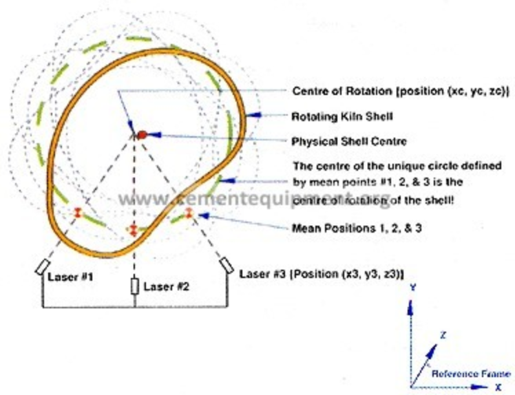
The advantages of being able to do this would be self evident. Such a method would have the directness and inherent accuracy promised by a bore sight alignment and also the advantages of an external procedure, that is measuring the position of the shell hot and running. By definition it would then be the ideal preventative maintenance tool since it can be scheduled any time the kiln is up and running. The fact that there is a rotating object, the shell, allows its centre of rotation to be found irrespective of the fact that it may not be circular and that it may have planetary motion. To do this it is only necessary to find three mean shell positions. Properly selected, these three positions will reveal the centre of rotation. The most important aspect to emphasize is, with the kiln in normal operation, the position of a series of support points have to be obtained by external measurement which can be aligned without knowing any details about the nature of the supports. This has been accomplished by finding centres of rotation as opposed to the physical centres of tyres and shell. Aligning these points then puts the shell in the lowest state of stress which can be achieved by positioning the support rollers.
- Introduction
- Historical preference for the internal bore sight alignment
- Limitations to the internal bore sight alignment
- Limitations of external procedures
- The Direct Method
- The apparatus
- A note on accuracy
- Final observations
- Conclusion
Introduction
Naturally, the intention is to establish alignment with the kiln in operation. The advantages of doing so are compelling. What is the Direct Method of alignment? – The Direct Method of alignment is to find the shell centre points to be aligned without any measurement of the support components, namely the tyres or the rollers, and doing this with the kiln in full operation. The advantages of being able to do this would be self evident. Such a method would have the directness and inherent accuracy promised by a bore sight alignment (Fig. 1), and also the advantages of an eternal procedure, that is measuring the position of the shell hot and running. By definition it would then be the ideal preventative maintenance tool since it can be scheduled.
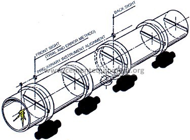 Fig. 1
Historical preference for the internal bore sight alignment
Bore sight alignment (Fig. 1) is almost always used in the erection of kiln shells when they are delivered to site in more than one section. For all but the shortest kilns this is usually the case. Subsequently, after the kiln has been lined with refractory and set into operation many users still prefer to check alignment using this internal technique This is the most direct method of alignment measurement because, unlike external procedures, it circumvents the need to measure the support component geometries. That is its great advantage. Unfortunately this advantage is more than offset by the need to shut the kiln down and have it 100% available for measurement. This is a shut down period where no other work can take place for the duration of the measurement work, and seriously detracts from using the alignment as a preventive maintenance tool. Working inside the kiln also presents physical challenges that compromise accuracy.
Limitations to the internal bore sight alignment
The internal bore sight alignment, in spite of the directness of shell position measurement, has some serious limitations. Each centre for a roller support station is found from a composition of several rotational kiln positions. As a minimum, 3 positions are necessary. More are preferred since the location of the centre, measured from the inside surface of the steel shell, will gain precision with the number of shell reference points. Each point, however, requires the coating on the brick, and the refractory brick itself, to be drilled. In addition, for each set of points the kiln has to be partly rotated. It is easy to understand that this is time consuming and, with the pressures to limit shut down time, the minimum procedures are usually accepted. Another limitation is that the kiln is necessarily measured in its cold condition. Cold, the kiln is not thermally expanded. This means that the centres are not in the same vertical locations, and the tyres are not in the same axial positions in relation to their respective pairs of support rollers, as they would be with the shell hot and expanded. Re- checking alignment after the roller adjustments have been made is not an option, at least until the next shut down.
Limitations of external procedures
To date, all external procedures (hot or cold), invariably take measurements to at least the tyre, and usually to the rollers as well. Whether these measurements are taken hot or cold does not matter to those procedures. These hot procedures are only variations and extensions of the standard cold procedure, and in principle they are all identical. Preference is given to measuring hot to avoid the limitations of the internal procedure as described. Although a great variety of techniques are used to measure a moving tyre diameter, and hence compute its centre position, such efforts are plagued with accuracy problems. Even when the location of the tyre centre has been computed, it is the shell that must be aligned. Most kilns have migrating tyres, which means their shell position within the tyre is eccentric. This phenomenon must be accounted for. The hot external methods therefore still have credibility problems with knowledgeable critics in some segments of the kiln user industry.
The Direct Method
It must be appreciated that the accuracy of the final alignment is only as good as the accuracy and reliability with which these “centre points” can be established. The direct method establishes these centre points in the same way as a bore sight alignment, that is by measurement to the shell rather than through measurement of the support components. The same principle of trammelling points from the inside of the shell is thus applied although now working from one of the shell. There are some differences. Namely there is no restriction to three (or any number) of discrete shell positions. Theoretically, any number of positions can be used provided the computer and measuring device can handle them. As a result the shell centre of rotation is obtained, and not just a physical centre of the shell. It goes without saying, when working externally, that there is no refractory, material coating or sometimes kiln chain to impede the work. The fact that there is a rotating object, the shell, allows its centre of rotation to be found irrespective of the fact that it may not be circular and that it may have planetary motion. To do this it is only necessary to find three mean shell positions. Properly selected, these three positions will reveal the centre of rotation (Fig. 2).
 Fig. 2
The dashed lines represent the rotation of the shell. Although only eight positions are indicated in this way the lasers each take 180 discrete readings during the course of one shell rotation. Technically, 180 shell positions should be shown but this would obscure the illustration. The 180 readings are arbitrary but are considered numerous enough to represent the entire surface of the shell. Each laser’s 180 readings are then averaged, producing three mean shell positions. Only one circle can be drawn through three points. The resulting circle does not really represent the shell, it is simply called the working diameter. The only significance of this circle is that its centre is the centre of rotation of the shell. If the shell had no component of planetary motion, which is virtually never the case given the nature of the shell, its physical centre would correspond to the centre of rotation. In practice the centre of rotation is always different from the shell’s physical centre as illustrated. The only thing that varies is the degree to which these points are separated. The centre of rotation at one cross section of the shell is found in this way. Performing this procedure once on the discharge side of each tyre and again on the in feed side of each tyre allows the interpolation of the centre of rotation for the centre of each tyre support. At this juncture a set of centres have been obtained, just like the bore sight method, the only difference being that the points are coordinate addresses in a 3 dimensional space. This then is the basic concept of the Direct Method. By definition it is clear that unlike other methods it can only be performed with the kiln in operation.
The apparatus
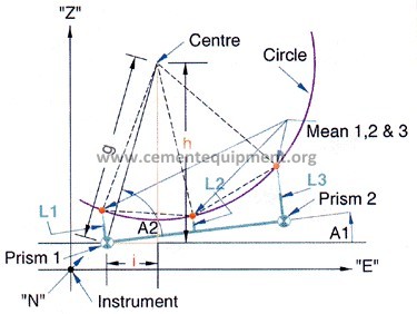 Fig. 3
Figure 3
Figure 3 shows the apparatus. “Instrument” means the position of the Integrate Total Station which will have coordinates (Ni, Ei, Zi) where N, E, Z are in millimetres (45023, 9467, 6251) (Fig. 4).
 Fig. 4
Figure 4
Prism 1 and Prism 2 denote the coordinate addresses of the two fixed prisms on the bridge, Pl (Npl, Epl, Zpl) and P2 (Np2, Ep2, Zp2) all in millimetres (Fig. 5). Ll, L2, L3 are variable dimensions com posed of a bridge constant, i.e. the physical location on the bridge which does not change from application to application, and the variable laser readings.
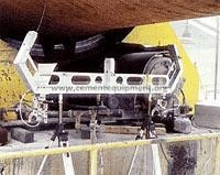
Figure 5
These laser readings are distance displacement measurements from the laser to the shell. The bridge assembly (Fig. 5) shows the three lasers, one centre and one at each end. Means 1, 2 & 3 are the computer calculated positions based on the respective averages of each of the 180 readings of Ll, L2 and L3. The three sets of 180 laser distance displacement readings are logged virtually simultaneously during the course of one shell rotation. The unique circle defined by the three means 1, 2 & 3 is shown to clarify the trigonometric calculation of the centre. Al is the angle the bridge makes to the horizontal. It is not necessary therefore that the technician sets the bridge level, although in most cases near level would be the most convenient for him. There are other criteria of placement which are adhered to. Adjustment capability ridge to facilitate this. A2 is an angle which will vary with kiln diameter. For the sake of brevity its derivation is not shown, but it is a simple trigonometric calculation given the bridge configuration and measured means 1, 2 & 3. Similarly, the derivations of g, h & i are not shown, but are also found by trigonometric calculation from the known points and distances. Centre; Given the bridge constants, that is the fixed relative positions of the three lasers and the two prisms, and the average of the three laser displacement readings it is therefore a straightforward trigonometric calculation to show that the centre coordinates are: Centre [Pl(N,,l), P1 where h=g sin(A1+A2) ,~d i = g-cos(Al+A2) The cross section of the kiln is at right angles to the “N” direction. In actuality this would be a rare coincidence. The kiln position is expected to be skewed to all axes since the coordinate grid is set before the kiln position is measured. The coordinates of the centres are therefore true threedimensional addresses. The centre of the shell at the centre of the support frame is interpolated from the two centres straddling a support tyre. This then yields a single point for each support. Their positions with respect to a straight line of a selected slope is then easily assessed. All the calculations are computer based. Their details are not needed for an understanding of the basic precepts.
A note on accuracy
Every kiln installation provides its own challenges that compromise the inherent accuracy of the instrumentation brought to the task of alignment measurement. In this sense the instrumentation described here is no more or less susceptible than that associated with any competent procedure. Absolute accuracy is therefore site specific. It goes without saying that instrument accuracy is always greater than the accuracy of the final results. So far the only concern has been to find the shell position. Any misalignment of the kiln position must now be translated into roller adjustment to correct the position. This requires a knowledge of the roller and tyre diameters. The advantages of the Direct Method measurements are best explained by example, which will also demonstrate why this method is inherently more accurate. A convenient set of tyre (7,000 mm) and roller (2,000 mm) diameters will be used for the kiln taken as an example (Fig. 6).
 Fig. 6
Figure 6
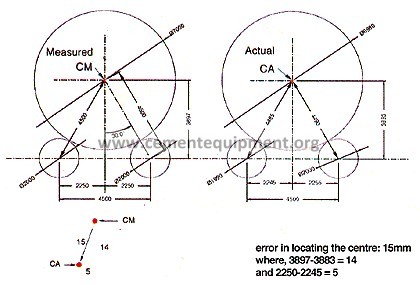
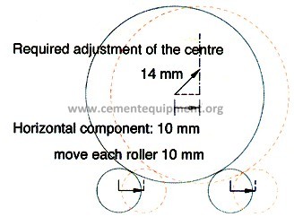
Consider first one point from a set of centres calculated using an external procedure. It will then be assumed that two errors were made. First, the tyre diameter is actually 6,980 mm, and secondly one roller diameter is actually 1,990 mm. The practitioner who does not know this but calculates his centre point through his support component measurements will mislocate the centre by 15 mm. Any variation of diameter errors or roller spacing mismeasurements will have similar results. The error in this case is 15 mm. Now to be fair the same error hypothesis will be imposed on the Direct Method. Having measured the alignment without having to know any of the diameters, a misalignment is indicated of 10 mm vertical direction and 10 mm horizontal direction. From this position it is necessary to calculate the appropriate roller moves to reposition the kiln, for which the diameters must now be introduced. For the horizontal correction both rollers can be moved to the right 10 mm (Fig. 7).
 Fig. 7
Figure 7
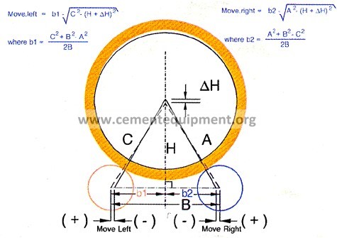
Next, the vertical correction must be calculated. First using the measured values, then with the actual values.
 Fig. 8
Figure 8
Shown in Fig. 8 is the calculation for the vertical adjustment. An actual value for DH of 10.16 mm was calculated backwards from having moved 17.41 but using the actual A, B & C values. The measurements of A, B & C are crude because of the nature of the kiln. However, it is clear that the error in placing the rollers is barely affected by using poor values for A, B and C. Using quick and simple measurements to verify these dimensions for the purpose of roller support movement calculations therefore hardly affects the results for the Direct Method. This is why the accuracy of obtaining an alignment measurement is totally independent of the condition of the rollers and tyres and the effect on roller adjustments is negligible. Unlike the simple external procedure which produced a 15 mm error in placing the centre, the Direct Method resulted in only a 0.16 mm error with the same mistaken roller and tyre dimensions. The inherent accuracy for this example is almost 100 times better. Even if the horizontal spacing is in error it can be clearly seen that the Direct Method has inherently better accuracy.
Final observations
The most important aspect to emphasize is that the positions of a series of support points have been obtained externally with the kiln in normal operation without knowing any details about the nature of the supports. This has been accomplished by finding centres of rotation as opposed to the physical centres of the tyres, shell, etc. In retrospect, it is considered that the centres of rotation are more representative of the dynamic position of the kiln. Aligning these points then puts the shell in the lowest state of stress that can be achieved by positioning the support rollers. Although there is always a measurable difference between the centre of rotation and the physical centre of the shell, this difference for all except kilns in poor mechanical condition is somewhat academic. In other words, most times it makes no significant difference. But, apart from not knowing in advance the kilns for which it does make a difference, the real advantage of focusing on the centres of rotation is that they represent the dynamic position of the shell during operation. Hence the name “direct”. Although the Direct Method is principally the same as the internal bore sight method, but carried out in an “in side out” fashion, it is not restricted to discrete shell positions. In addition, there is not only a vastly increased volume of data for supporting the calculation of the centre positions, but also the option is available of repeating and verifying positions after roller adjustments or at any time for whatever reason. The Direct Method of alignment also includes ovality measurements. Ovality is the measure of the dynamic change of shell curvature caused by rotation. Ovality is of primary interest with regard to the mechanical stability of the refractory lining. However, a detailed analysis of the curves as presented by the electronic ovality beam often reveals information useful in completing an alignment analysis. Significant differential ovality from one pier to the next can be used to correct the alignment recommendations when appropriate.
Conclusion
The kiln must be aligned so that flexing and distortion of the kiln shell are minimized and that loads on the support bearings are properly shared. Flexing and distortion of the kiln shell vastly increases mechanical wear and tear and can severely reduce refractory brick life. Poor load sharing amongst the supports leads to roller and bearing problems as well. Measuring alignment, with the kiln in full operation, accurately and reliably, requires an innovative approach. The Direct Method is that innovation making it a truly preventative maintenance tool. Now it is possible to align an operating kiln precisely.


The New Bore Site Alignment
The New Bore Sight Alignment
Using the Centers of Rotation for Bore Sight Alignment of Rotary Kilns Walter M. Gebhart P.Eng., Vice President, Phillips Kiln Services Ltd. Ronald W.T. Birchard P.Eng. Consultant [email protected]
Dave Roberts Manager, Alignment Services, Phillips Kiln Services Ltd.
Introduction
Although “The Direct Method”1 for measuring the alignment of rotating kiln shells has become a procedure of choice for many kiln operators world wide, it has one limitation. The kiln must be in operation in order to make the measurements. For the most part this is a strong advantage but when major repair work is underway, such as changing a shell section, where aligning the new section is a critical step, a bore sighting may still be necessary. Techniques involving rotation to align the field joints of the new section(s) still have the advantage but there are situations where this may not be possible. An example of that may be a kiln with planetary coolers when one of the field joints is between the inlet area of the coolers and the supporting tire immediately up-hill of this area. Securing the shell joint sufficiently to permit turning for the purpose of alignment may be prohibitive. In such a case a “bore sighting” as has been done for decades is the obvious solution.
The adaptation of some standard alignment techniques can make bore sight measurements significantly easier to perform than what is conventionally done2 .
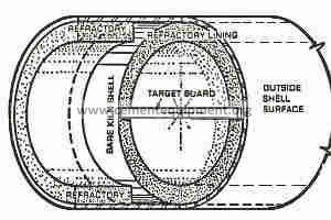
The Direct Method1 (performed while the kiln is in normal operation) utilizes the turning shell to identify the point about which it rotates at each roller support. A typical bore sight procedure2 (always performed with a cold, shut-down kiln) involves setting up physical target plates inside the kiln on which a center is determined by direct measurement from the inside of the shell plate.
This requires removing areas of refractory at each roller support station to expose sufficient areas to do this. See Fig 45.2
The Direct Method, a hot alignment technique (performed while the kiln is in normal operation) was developed from the principle of the bore sight. The Direct Method does continuous scans on the outside of the moving shell to determine a center of rotation. The center of rotation is virtually always different from the mean shell center. This may be academic in most cases but significantly the center of rotation is more accurately and reliably identifiable. The bore sight using the center of rotation instead of the mean shell center, is less work as well. The reason for this is because there is no need to measure to the inside of the shell. It is also possible to fix the target stands without refractory removal. This means significant savings of time and labor. Additionally it is done with far fewer rotations than that necessary to “trammel in” the centers compared to the conventional method 2. Thirdly the center of rotation is established entirely independently of the shape of theshell. This last point may often be the most significant in terms of accuracy since a distorted shell introduces uncertainty in determining a mean shell center. Finally, if done carefully, the effects of ovality (shape distortion due to flexing) can also be all but eliminated.
This is an ironic development since the bore sight inspired the development of the external, hot alignment, “Direct Method” procedure, and in turn, the Direct Method is now used to redefine the bore sight technique.
The New Bore Sight Alignment
The following is not meant to be a definitive description of the new bore sight alignment methodology but a simple outline so that anyone not familiar with the procedure can grasp a general appreciation of it.
Establishing the axis of rotation is done after the kiln is shut down but before any cutting of the shell commences. The shell is then cut and the replacement section can be aligned to that axis without rotating the shell.
An alignment scope (one equipped with visible laser light is a very convenient tool in this case) is placed immediately outside of the kiln. This is typically at the discharge end on the burner floor with the hood set aside. A position is roughed in using a tape measure etc. to place the instrument’s optical center approximately near the center of the open ended shell. Two positions along the interior length of the shell are then selected as target locations. We can assume the typical scenario where, on a three pier kiln, the first 20 meters of shell, including the first tire section, will be replaced. We would then select the center of tires two and three as reference target locations. At each of these reference positions target fixtures are installed. This fixture is usually a robust post welded to the shell, reaching radially inward to the center where a target plate is attached. This requires some refractory removal, perhaps only two bricks at the base of each post.
Also possible, is using a fixture which spans the diameter of the kiln, one leg firmly anchored into the refractory, the other leg firmly held against the refractory by a spring of considerable force. At the center is its target plate. There are certain physical requirements for this target fixture such that it does not sag when suspended horizontally inside the kiln and such that its movement, as a result of kiln shell flexing, is minimized. Two such target fixtures are then placed at the desired locations with the target plate roughly centered in the open area of the interior of the kiln. The advantage of not having to remove any refractory with this type of fixture is offset by the need for having such correctly designed fixtures available. The soundness of the refractory in those locations is then also an issue to be dealt with. In either case the target stands should be in-line along the length of the shell. On a case by case basis, judgement needs to be exercised in deciding on which fixtures to use.
With targets now in place the shell is rotated to a position where the fixed end of the target stands are positioned at approximately 3 o’clock. The scope is then aimed at the farthest target, Fig A. The spot on which it is focused is then marked on that target. Then, sighting the near target, a spot is marked on it. The roughed in position of the alignment scope must be close enough to accomplish this.
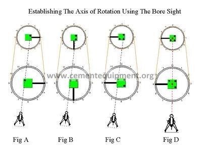
The kiln is then rotated so the fixed ends of the stands are approximately in the 6 o’clock position.
Without having adjusted the alignment scope in any way, a second mark is put on each target, Fig B. Again the kiln is rotated to a position where the fixed ends of the stands are now in the 9 o’clock position. Still without any adjustment to the scope a third point is marked on each target, Fig C. Naturally the rough adjustment of the position of the scope must be such that all six points land in the target areas. The accuracy of the results does not depend on the exact amount of rotation.
The similarity with the Direct Method is now evident. Having three points, with simple geometry, defines the center of rotation, Fig E. The two centers of rotation so derived, one on each target, now define the axis of rotation of the shell, Fig D. As confirmation, an additional rotation to repeat the procedure, can be made.
Given that the sighting scope is mounted with horizontal and vertical adjustment means, it should now be repositioned so that its line of sight is coincident with these two center points. With the instrument so positioned, monuments can then be set at convenient places outside the kiln so that the axis of shell rotation can be re-established at any time thereafter without having to re-introduce targets inside the kiln. This can have a variety of immediate or future uses. This last step is best accomplished using a total integrated station rather than a simple theodolite. If the external monuments are prisms, conventional re-sectioning and other standard surveying procedures can be used to accurately relocate the instrument in the future. For best results the instrument positionand the reference targets should be well barricaded so that they are never disturbed throughout the course of the kiln work at hand.
Limitations
In using this technique one must be aware of the significant effect of shell flexing and its resulting change of shape with rotation. This is similar to the change of shape of a car tire. It always has a flat spot where it contacts the road, even while underway. The change of shape of the kiln shell is more complex than that of a car tire, it having flat areas at the top, and to a lesser degree, in the vicinity of the rollers. The fixed end of the fixture should therefore not be positioned in those areas during the procedure. For that consideration the clock positions for the target stands as described above are chosen. However, when a tire is known to be abnormally loose on the shell, better results would be obtained if the upper locations are dropped below the 3 and 9 o’clock positions approaching 4 and 8 o’clock respectively.
When using a visible laser to strike the centerline another apparent limitation is beam divergence. Even with instruments that can focus the laser at set distances, divergence is unacceptable at 100+ meters. Some simple steps can be taken to restore its resolution to about 1 mm diameter even at these distances.
Conclusion
A very precise axis of rotation can be obtained in this way using simple, yet well established techniques, by removing little if any refractory and without any measurements to the kiln’s shell. The axis so established can now be used to position and align a new section of shell without further turning of the kiln.
Although the technique is simple in principle, its successful application is dependent on appropriate fixturing and suitable means for instrument installation / manipulation. None of these are mysterious but are usually not part of a plants normal maintenance facility. The specialist who performs these tasks on a routine basis, who has the fixtures available, is usually the most cost effective choice.
To conclude, as stated at the outset, external alignment procedures, based on finding centers of rotation, are superior to internal methods. This is also true for most cases of shell section replacement work. But when it becomes impractical to turn the shell for alignment trials, the advantages of using bore sight alignment is a formidable alternative.
Kiln alignment and shell ovality: a new approach
Kiln alignment and shell ovality: a new approach
Walter M. Gebhart General Manager, Vice-President of International Sales, Phillips Kiln Service Company Ltd, Sioux City, Iowa, USA.
Introduction
Analysis of kiln alignment and ovality characteristics are important tools which can help to improve or maintain the mechanical stability of a kiln. As cement plants are becoming more maintenance-oriented, the rotary kiln industry has responded with various techniques to determine this information. This report will examine various methods of measuring alignment and ovality and will describe the latest technological developments.
Internal vs. external methods
To overcome this difficulty, both internal and external methods have been developed. However, there are many limitations inherent in both methods. For internal methods to be successful, the kiln must be down. There is often very limited time to take measurements in working conditions that can be very hostile. There is often competition with other activities in and around a kiln during a shutdown period. The kiln must be repositioned at least three times to give some indication of the center of rotation rather than just the geometric center of the shell. An internal alignment analysis can offer accuracy but the data is not sensitive to the kiln’s operating conditions and can be very expensive to obtain in terms of lost production. In addition, there is no chance for verification of the data until the next shutdown. Traditional external alignment measurement on an operating kiln offers a different set of problems. The heat and motion of the operating kiln can make difficult working conditions even worse. Because the kiln is in motion, more complex data collection procedures are required. Data collected can be inherently less accurate because assumptions must be made as to the creep or tire shell gap. In many cases, inappropriate measurement procedures and instruments may be used if those performing the analysis are inexperienced. Depending on the methods used, reasonable to questionable results can be obtained at a relatively low cost with no downtime. External alignment methods are sensitive to the kiln’s operating conditions and can be verified any time the kiln is operating. Traditional external alignment procedures have various methods of data acquisition ranging from plumb bobs draped over moving tires and piano wire stretched along the roller bases to sophisticated computerized systems and theodolites. All traditional external alignment methods, however, have a common limitation. They all attempt to determine the kiln center based on component geometry (ring and roller diameters, tire/shell gap, and spacing between roller centers) (See Figure 1).
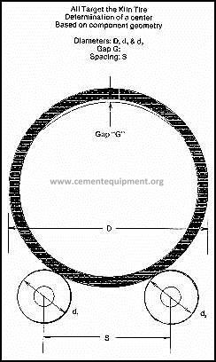 Figure 1
On a moving kiln, it may be very difficult to obtain precise component measurements.
Assumptions about the tire/shell gap are often factored into the alignment calculations resulting in potentially inaccurate data. Some external alignment methods use other indirect phenomenon such as ovality as an indication of misalignment. Although ovality curves do show an indication of alignment, it is important to remember that the indication is only qualitative and that damaged shell plate can radically affect the ovality curves as do many other factors. The use of ovality in calculating alignment characteristics is largely a subjective interpretation. Consequently, traditional, internal or external alignment methods present many obstacles including high downtime costs and dubious results. Because of these problems, alignment checks are done infrequently, usually only when kiln damage is evident. The alignment is done after the problem manifests itself rather than as the preventative maintenance tool it could be. Therefore, most kilns run in less than optimum conditions. Accelerated wear, frequent component failure, and high longterm costs of kiln operation have become accepted norms in some industries.
New alignment technology
A new concept in alignment measurement has emerged which eliminates the major limitation of traditional external alignment methods. This procedure, based on new technology, determines the centers of rotation, independent of component geometry. Using linear measurements from an arbitrarily chosen frame of reference outside the kiln, the true center of rotation of the kiln is determined (see Figure 2).
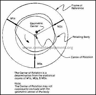 Figure 2
The practical application of this new procedure has many advantages over traditional internal or external alignment methods:
- The final report is presented to and reviewed with plant personnel before the crew leaves the job site.
- The procedure is comparatively simpler, with measurements taken directly on the kiln shell.
- Diameters, surface conditions, gaps and spacing are not factors in determining the kiln alignment.
- Electronic measurement allows for self checking data, perpendicular measurements (unaffected by thermal conditions of the kiln), and high frequency measurement rates.
- Measurements are direct functions of the centers of shell rotation (not the geometric centers) and not related to features such as diameters or ovalities.
- Statistical determination of the center of rotation of each support is typically based on over 2000 readings which are logged over the course of numerous revolutions.
- There is no limit of applications. Kilns of all types, speeds and processes can be analyzed with no downtime. The patented alignment procedure, performed exclusively by Phillips Kiln Services, is successfully completed on over 50 kilns per year.
Ovality
In addition to new alignment technology, a breakthrough has recently been made in kiln shell ovality analysis. Although ovality is sometimes influenced by alignment, it is always of interest and concern with respect to the mechanical stability of refractory. Ovality, as it applies to an operating kiln shell, is the change of curvature or flexing of the shell during the course of each revolution.
The first practical device to actually measure ovality was patented in 1953 by E.R.S. Kareby of
Stockholm, Sweden, and was assigned to Skanska, AB, also of Stockholm. In the early 1960s,
Holderbank designed improvements for the device and made it commercially available as the THS Shell Test Apparatus. It has been very successful and up to now, the standard of the industry. There are some practical limitations to the device, however. If not handled properly, its weight can cause it to fall from the shell and damage the delicate mechanical leverage and tracing mechanisms. Proper attachment to the shell to get the best possible tracing is a challenge especially with larger diameter, fast moving kilns. It is not unusual to reduce the kiln speed to properly place the instrument. The Shell Test Apparatus produces circular chart recordings which resemble the cross section of a kiln shell, creating a visual impression of the degree of ovality. Actual mathematical calculation, however, requires measuring the curves using a simple draftsman’s scale. Since the diameter of the graph is only 3 in. and the chart is drawn with a pencil, accuracy is compromised. Therefore, the circular graph cannot offer much detail.
Advances in ovality measurement
The first significant improvement in almost 30 years has been made with the development of the
High Resolution Ovality Beam (HR Beam). The leverage and tracing mechanisms of the Shell Test Apparatus were replaced with an electronic unit and data logger which opened a whole new world of detail. The difference in the viewing capabilities of the two machines can be comparable to the naked eye versus a microscope. In addition to the enhanced ovality measuring capabilities, the HR Beam is also able to detect other aspects of kiln shell reactions. The HR Beam easily identifies the following shell abnormalities:
- Heavily loaded piers or undersized support components
- Excessive tire/shell gaps
- Bowed shell
- Under-loaded piers
- Misalignment
- Cracked shell
- Damaged or distorted shell plate
As with the original Shell Test Apparatus, great care was exercised to design a High Resolution Beam that would be stable with respect to thermal expansion. The thermally stable design of the new beam has an added advantage. Any thermal effects on the beam are clearly reflected in the data, allowing for computer correction to eliminate the temperature gradient in the data and in the resulting ovality curves. The new beam offers high resolution in a more practical device. The replacement of the mechanical leverage and tracing system with an electronic package has resulted in a much lighter and more compact beam which is much easier to use. The timeconsuming adjustments necessary with the Shell Test Apparatus (proper pendulum action, pencil position/pressure/sharpness, etc.) are not required with the HR Beam. To operate the HR Beam, just put it on the shell and push a button to start the electronic readings which will be digitally fed into the data logger. The data logger can hold an entire set of data for a kiln and keep it in subsets according to location. Downloading the data to a computer program then allows data processing and graphing. Optionally, a data logger to process data and send the report and graph to a standard printer is also available. Another departure from the Shell Test Apparatus is the appearance of the ovality graphs. The traditional ovality graphing method was on a circular graph or polar plots. The somewhat superficial appearances of a kiln cross-section can actually hide details and cloud the evaluation. The HR Beam charts the ovality data on an X-Y plot (See figure 3).
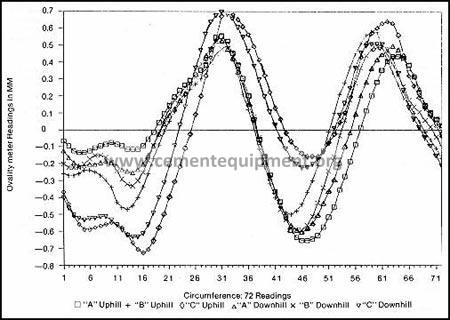
Figure 3
With a circular graph a change in curvature represents a deviation from the circle. In the X-Y plot, a change in curvature is a deviation from a straight line. The eye is much more adept at judging what is a straight line than what is a true circle. In interpreting an HR Beam ovality curve, it is important to understand the concept of kiln ovality. An ideal kiln shell is one that is 100% rigid, does not flex, and would display no ovality. If measured by an HR Beam, the ideal kiln shell would produce a straight line curve. All kiln tires flex, however, to a varying degree. Since the kiln shell is thinner than the tires, it is similar to a bag of water in a container. There is a tendency for the kiln shell to assume the shape of the tire. As a result, there are three distinct changes of curvature exhibited by a normal and well proportioned kiln shell:
1. Because the tire is supported primarily at the bottom, its own weight will cause it to sit flat. This flattening of the tire makes the horizontal axis a little longer than the vertical axis. As a result, the degree of curvature at the 3 and 9 o’clock positions is greater (more positive on the X-Y plot) compared to the 12 and 6 o’clock positions (See Figure 4(a)). 2. Each tire has two point loads where it sits on the two support rollers. The two point loads work to straighten out the tire. As a result, the degree of curvature decreases from the nominal at each roller. This decrease in curvature shows as a negative dip on the X-Y plot (See Figure 4(b)). 3. As the shell flexes inside the tire, a gap forms between the shell and tire at the 12 o’clock position. Here the shell becomes more flat than the tire and another decrease in curvature is recorded as a negative dip on the X-Y plot.
Keeping the normal curve pattern in mind, deviations can be easily identified. The stylized curves in Figures 5(a) to 5(f) were taken from actual kiln readings and serve to illustrate the most common types of ovality problems. Although the normal ovality curve is easily identified by shape, it cannot be categorized to an absolute scale. There is, however, an overall ovality range within which curves should fall. This range has been empirically derived over many years and serves as an overall guide for ovality analysis. The considerable spread within that range allows for the fact that all kilns are not created equal nor are the loadings from tire to tire expected to be equal on the same kiln. These detailed aspects of ovality are significant for their qualitative or pictorial value. They serve to highlight and corroborate misalignment and other problems but could be very misleading if not used in conjunction with other data when trying to sort out the many factors affecting them. An example of this is a misaligned roller. The curve would indicate a misalignment but could not by itself be used to determine how much a roller should be moved to gain alignment. To align a kiln to arbitrarily ‘balance’ ovalities pier to pier, (which is nearly impossible with a bowed shell) ignores a host of other considerations and often creates other problems.
Summary
Ovality, or the degree of change of curvature of the kiln shell during rotation, has always been of interest and concern with respect to the mechanical stability of refractory. The Ovality beam, or ‘Shell Test’ rig, continues to be a popular mechanical device used to measure the degree of flexing a shell undergoes during normal operation. With the advent of digital technology, the simple pencil tracings produced by the shell test mechanism have now been replaced by a device which takes digital readings whose graphs reveal the microcosm of changes in shell curvature during rotation. For discerning kiln users who operate large and/or fast moving kilns, particularly the cement industry, the ability of this state-of-the-art ovality beam to spot overloaded piers, excessive tire/shell gaps, a bowed shell, under-loaded piers, misalignment, and even shell cracks, this stateof-the-art ovality beam will be of considerable interest.
Differential axial shell deflection
Differential axial shell deflection – Is This A Problem With Your Kiln?
by Walter Gebhart,V.P., Phillips Kiln Services
Previously published in International Cement Journal, 6/98
The serious and not uncommon problem of differential axial shell deflection is a cause for aggressive mechanical wear. Symptoms are undercut side walls of the kiln’s support tires with complimentary abrasion on the tire’s retaining elements. The resulting axial play of the support tyre on the shell will produce secondary problems of uneven rolling surface wear and if the condition exists on the thrust tyre, axial shell drift which will affect the drive and shell end seals. The condition will only be found on rotary kilns with migrating tyres.
What is differential axial shell deflection?
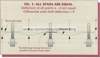
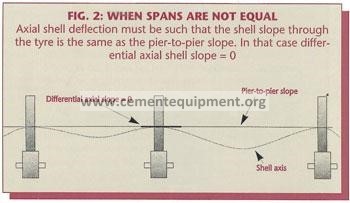
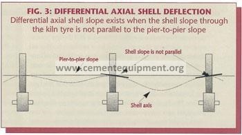
There are several categories of shell deflection, among them ovality, which is radial deflection resulting from shell rotation and secondly shell sag, which is axial deflection between the support piers. In its simplest form (when the spans are of equal length) differential axial shell deflection occurs when the amount of sag from a middle pier is not equal in the up-hill and down-hill spans. In the more general case, with unequal spans, sag to each side of the tyre must be such that the shell axis going through the tyre remains parallel to the pier to pier slope of the kiln. See Fig 2. If this is not the case we can say that the shell has differential axial deflection. Fig 3.
What is the cause of differential axial shell deflection?
The root cause is an inappropriate axial location of a set of support rollers. This means that the amount of load in the kiln along with the shell weight itself, is greater in one direction from the support as it is in the opposite direction. The direction being axially up-hill vs. down-hill or vice versa. It is uneven load distribution. Kiln design engineers are careful to properly position the supports to avoid this problem but kilns in use for many years undergo modifications to accommodate changes in processes or to make use of different refractory materials. Many kilns have shell length and piers added or subtracted. Any such change may result, unavoidably or unintentionally, in a load distribution that causes differential axial shell deflection.
How can this condition be identified?
Aggressive wear on the sides of the tyres and their retaining elements is a symptom already noted but there are other causes that produce the same symptoms. How can one be sure that differential axial shell deflection is a factor? The more common causes of aggressive wear should naturally be eliminated first. This means, roller skew, alignment, flat non-tapered rolling surfaces, and properly secured and sloped base frames, etc. must all prevail. If, and when all these conditions are reasonably correct and aggressive wear still takes place, a case of differential axial shell deflection may be suspected.
Can differential axial shell deflection be measured?
Although it is not commonly done, alignment measurements made using “The Direct Method For Aligning Rotary Kilns” (ZKG No.11/95) could directly measure this condition if additional points were to be included in the survey. Ovality measurement, a much easier and quicker procedure to perform, can also show the presence of differential axial shell deflection. Although ovality is a measure of radial (and not axial) shell flexing it can be used to show indirectly the presence of differential axial deflection.
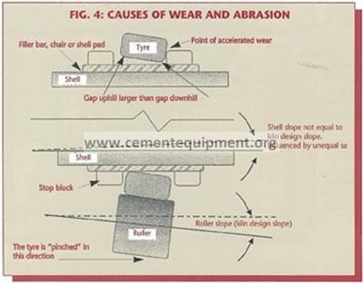
Consider Fig. #4. Firstly, the shell and its support elements attached to the shell between it and the tyre have a smaller diameter than does the bore of the tyre. This is always the case with a migrating tyre type design. It is a very common design which has been used for decades to accommodate differential thermal expansion between the shell and the tire. Secondly, the support forces are such that the tyre has a natural tendency to sit and align itself to be flat on the rollers. Thirdly, if the shell has a greater sag in one direction compared to the opposite direction, its inclination, for the short length through the tire, will not be the same as the rollers’. There are several consequences when such a condition prevails. (a) The apparent gap between the tyre and the top of the shell will not be the same at one side of the tyre compared to the other. And (b) the difference in slope between the shell and the supporting rollers will cause the tyre to be pinched into the direction of least axial deflection. This last situation creates heavy axial loading onto the tyre’s retaining elements creating the excessive wear. Additionally (c) if the retainers are too tight a tipping component is introduced which prevents the tire from sitting flat on the rollers. Until sufficient clearance is worn in, this will accelerate the wear. We have seen a situation where a new set of retainers were completely abraided away in a matter of weeks. Unfortunately, the additional axial clearance the tire then acquires through such wear, does not relieve the situation. The mismatched slopes continue to force, or pinch the tyre, into the direction of the least axial deflection. Consequently the wear and abrasion continue unabatedly.
This condition is also often the cause for tyres to persistently sit against either the up-hill (feedend) or down-hill (discharge-end) retainers irrespective of various attempts to “float” them.
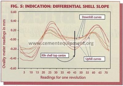
Figure 5 shows the ovality measurement raw data curves of a shell which does not sit straight within its supporting tyre. Ovality measurements typically consist of three measurements on the shell up-hill of the tire and three down-hill. These are noted as ‘A’, ‘B’, and ‘C’ up-hill and as ‘A’, ‘B’, and ‘C’ down-hill respectively. The data is graphed in the linear form as opposed to the more common radial form so that the differences in the curves are more easily seen. In this format the size of the gap at the top of the kiln is characterized by the “deepness” of the large dip in the curve as noted, fig 5. The larger the gap, the deeper the dip. It is significant to observe therefore, that the three curves down-hill of the shell, are consistently less “deep” than the three curves taken up-hill of this same tire. This measurement clearly shows there is less gap between the shell and the tire on the downhill side compared to the up-hill side. Since this pattern is consistent around the circumference, the ‘A’, ‘B’, and ‘C’ readings being 120° apart from each other, it is not a result of a “crank” in the shell. The resolution of the electronic ovality measurement instrument easily picks up this and other shell flexing characteristics. Conceivably, a hotter shell on the downhill side of the tire could also account for this phenomenon. No ovality measurement would be complete without tire, shell up-hill and shell down-hill, average temperatures being taken at the same time. If temperature is not a factor this is the unmistakable signature of differential axial shell deflection. We say it is indirect since, no matter how clearly its presence is seen here, the amount of the difference in slope is not attainable from this measurement alone.
How can differential axial shell deflection be corrected?
Truly resolving the problem is to either change the load distribution in the kiln or change the location of the support rollers. The latter is rarely a practical option unless it is part of a massive kiln rebuild program. Even changing the load distribution in the kiln is not often a realistic option. It is only when such imbalance of loads is in itself a result of a process problem that it does become viable. The simple example here is an unusual coating or ring build-up due to a feed chemistry anomaly. The coating / ring material adds considerably weight as does the material it holds back. If this additional weight acts predominantly in one span, differential axial shell deflection will result. Reestablishing the feed chemistry then resolves both problems. Dramatic examples of this situation have been observed.
For the majority of cases, where the problem has unintentionally arisen out of a combination of circumstances, the only practical answer is to “live with it”. This does not mean accepting wear and extraordinary repair costs. Rather than eliminating differential axial shell deflection, it means designing the mechanical components to properly carry the additional loads created by it.
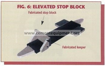
Many kilns have retaining elements that simply do not provide sufficient bearing area against the side of the tyres. Enlarging this bearing area, see fig 6., could significantly reduce the unit loading and bring abrasion and wear well within acceptable limits.
Lubrication of these sliding and rubbing surfaces will also improve their performance. Graphite, molybdenum, copper, aluminum and other solid lubricating materials are appropriate for this application. There are a variety of compounds specifically formulated for this application available.Solid lubrication bars that are inserted between the pads and the riding ring are an ideal solution.
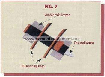
If the problem exists at the thrust tyre, enlargement of the bearing area is restricted. In this case sacrificial elements, such as retaining rings that can be easily replaced, provide superior service. (Fig 7).
Another common “fix” is to reset the bearing base or shim the support roller bearing housing to match the prevailing slope of the shell in this area rather than the pier to pier slope. This often ends up being a somewhat trial-and-error procedure but it does not have to be. It is possible, as stated before, by determining the elevation of several centers of rotation actually to measure the prevailing slope of the shell as it passes through the tyre. This can only be done with the appropriate kiln alignment measurement method, namely by the Direct Method of Kiln Alignment (The Method by Centers of Rotation). Once the prevailing local shell slope is known, accurately setting the base or calculating bearing housing shims is straightforward.
An even better although more costly approach is to utilize a pivoting roller support base. This requires completely re-building the top of the pier and installing such a new base. New, two support, gear-less, trunnion driven kilns use this concept. This has a further and very significant advantage because the roller is then free to follow the inevitable tyre wobble as well. This will greatly reduce the wear and tear on all the support elements.
The saying “an ounce of prevention is worth a pound of cure”, is a cliche, but it is still valuable conventional wisdom. When purchasing a kiln and more importantly when modifying a kiln, either its refractory layout, adding dams or changing shell length and or the number of its piers, closely analyzing its axial deflection curve must not be omitted. Differential axial shell deflection is a lot easier to prevent on the drafting table than it is to resolve once the kiln is in operation.