Contents
click here to Download the Most Important 13 Books in Cement Industry
click here to Download the Most Important 13 Books in Cement Industry
What is reason of “Red River” phenomenon in grate cooler?
By: Nael Shabana qatar.cement@yahoo.com
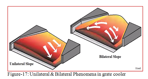
Red river is a phenomenon in grate cooler (figure-16); it is often a red hot narrow stream of fine clinker with a higher temperature than the neighbored clinker and appears far down in the cooler. The fact that especially large diameter type kilns tend to discharge fine clinker on the kiln’s load side and coarse clinker on the opposite side can make it difficult to get good clinker distribution. In addition to the segregation, a clinker bed with unilateral or bilateral slope on static grate tends to slide fine clinker down as shown in figure-17.


A fine clinker has a higher resistance to the airflow than the coarse clinker, so the cooling air takes the path of least resistance, which intensifies the “Red River” formation. Figure-19 shows the pressure losses of various clinker sizes as a function of free air velocity. It can be seen that the particle size has a great influence on air distribution, which can be described by pressure losses.

Proper clinker bed distribution on cooler grates by optimization cooler
parameters may help us to avoid this phenomenon. Here are the main points
need to be considered with grate cooler:
1). Increasing the clinker bed thickness by slowing grate s peed improves the overall clinker distribution and heat transfer, also has a positive effect upon grate wear rates. Slowing down the movement of the fine clinker bed diverts more fine clinker to the coarse cooler side, thus increases the overall clinker bed
resistance which pushes more air through the fine clinker bed. (good results have been experienced with clinker beds up to 1 meter deep).
2). Optimization of cooler air flow as too high amounts of air promote fluidization of the clinker. As the finer clinker particles are likely to be entrained in the locally intensified air flow, high amounts of dust cycles between kiln and cooler are likely. Dust particles might also be picked up from highly fluidized areas and concentrate in others, thereby intensifying any red rivers. It is recommended that maximum airflow not exceed approximately 140 normal cubic meters per minute per square meter of cooler grate area.
3). A successful way to improve clinker distribution is to narrow the cooler grate area on the fine clinker side. By doing so, the clinker bed becomes narrower and often eliminates a severe segregation of fine and coarse clinker. It is recommended that the cooler inlet grate width not exceed 2.5 m for kiln capacities up to 2,500 metric tons per day of clinker.
4). Corner areas often have a low clinker load which results in heavy air channeling and bypassing the clinker load. Blanked off air holes ensure that cooling air is diverted into the clinker load.
5). Optimization of secondary air temperature as too high secondary temperature tends to form “snowman” which cause poor clinker distribution at cooler inlet where improvement should start from.
click here to Download the Most Important 13 Books in Cement Industry
click here to Download the Most Important 13 Books in Cement Industry