Contents
click here to Download the Most Important 13 Books in Cement Industry
click here to Download the Most Important 13 Books in Cement Industry
EVERYTHING YOU NEED TO KNOW ABOUT THE CHEMISTRY OF KILN FEED AND CLINKER
RAW MATERIALS
The basic ingredients for portland cement consist of limestone, sea shells, marl, or chalk, that provide the calcareous components; clay, shale, slate, or sand, to provide the silica and alumina; and iron ore, mill scale, or similar material to provide the iron components. The number of raw materials required at any one plant depends upon the composition of these materials and the types of cement being produced. To effect the proper blend, raw materials are continually sampled and analyzed, and the proportions adjusted as they are blended together.
After being excavated in the quarry or mine, limestone is first passed through the primary crusher then to the secondary crusher where it is reduced to about 3/8 in. in size. At this point other raw materials are blended with the limestone and the blend is conveyed to raw storage piles. Samples, mentioned above, are obtained at this point and immediately analyzed. In a modem plant this sampling and testing is the source of data fed into a digital computer controlling composition of stored and blended raw feed.
In the dry process, the material is now removed from the blending piles and delivered to the raw grinding mills, where it is reduced in size until about 90% passes the 200-mesh screen.
In the wet process, the raw feed is transferred from raw storage piles to the grinding mills, which are substantially the same as the ball, tube, or compartment mills used for dry grinding. Introduction of water into the mill along with the feed results in the formation of a slurry. After grinding, dry kiln feed or slurry is drawn from storage and fed into the rotary kiln.
CHEMICAL AND PHYSICAL PROPERTIES
Usually, any one constituent of the blended kiln feed can be found in more than one of the raw materials. For example, typical·raw materials might contain key oxides in the proportions shown in Table 9.1.
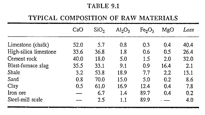
From such typical raw materials, a plant chemist tries to obtain a kiln feed mix that contains a predetermined oxide amount of calcium (CaO), silica (Si02), alumina (AI203) and iron (F 03). In some locations,mixing of only two or three different raw materials accomplishes this,whereas in some other plants it might need up to four or five different materials to achieve the same results.
In addition to these basic oxides, r w materials also contain a certain percentage of so-called impurities which show up in the kiln-feed mix. Magnesia (MgO), in some plants can amount to levels of 4.2% in the mix which, if not properly controlled, can lead to unsound (expansion) cement. Magnesia acts as a flux at sintering temperatures which renders the burning slightly easier. However, a magnesia-rich kiln feed tends to .”ball” easily in the burning zone which, from an operator’s viewpoint, is considered an undesirable property.
Clinker, made from magnesia-rich feed must be very rapidly cooled once it has been burned, to guard against production of unsound clinker. Plants faced with this problem usually locate the burning zone very close to the discharge end of the kiln and have quick quench compartments at the inlet to the cooler.
Oxides of potassium (K2O) and sodium (Na20), commonly referred to as alkalies, are impurities that not only have a deleterious effect on cement quality but can pose considerable operating problems particularly in a preheater kiln. Of the two alkalies, potassium is by far the predominant im purity that needs close attention from the plant chemist. During the burn ing process, alkalies vaporize in the lower part of the burning zone, travel with the kiln gases to the rear of the kiln, and condense again at a gas tem perature of around 900 C (1650 F). These alkalies react in the colder part of the kiln with sulfur dioxide, carbon dioxide, and chlorides that are con tained in the kiln gases. Thus, an internal alkali cycle is created that can lead to troublesome buildup and ring formations in the kiln. In dry- and wet-process kilns, condensation of alkalies occurs in the lower end or just below the chain section whereas in preheater, semidry, and precalciner kilns this condensation takes place in the lower stages of the preheater tower or grate preheater. Alkalies are quite an intriguing problem for any kiln manager. There must not be too much of them in the clinker; they should not be recycled and allowed to accumulate in the kiln; and yet they are found in great quantities in the raw materials. To combat these problems, various means are employed to keep these alkalies under control. In wet- and dry-process plants, part or all of the kiln dust collected in the baghouse or electrostatic precipitator must be wasted. Some plants are fortunate in that they have to waste only the last section of these dust collectors, i.e., the very fine dust particles that are richest in alkalies. Some of these plants sell this potassium-rich kiln dust as fertilizer. Preheater and precalciner kilns are equipped with alkali bypass systems at the preheater tower to control this internal alkali cycle.
There are also plants that could tolerate a slightly higher alkali content in the clinker but face the trouble of large, internal alkali cycles which call,for different solutions to inhibit the vaporization of alkalies.
Sulfur (S03) is introduced into the kiln by the raw materials and the fuel. this impurity will also vaporize to form sulfur dioxide (S02) at a temperature of = 1000 C (1832 F) and condense in the form of sulfates within the kiln system. They readily combine with calcium to form calcium sulfates and potassium to form potassium sulfate both of which are the prime culprits for ring and buildup problems in the upper half of the kiln system. If there is a Jack of aikalies present with which the sulfur dioxide would combine to form alkali-sulfates then much of the sulfur dioxide would leave the kiln system with the kiln gases.
Experience gathered by many plant operators has shown that there should be a delicate balance between the alkali and sulfur contents in the raw mix. If the molecular ratio of alkalies-to-sulfur is significantly below 1.0 this gives rise to calcium sulfate buildups near the kiln inlet in pre heater kilns. By raising this ratio to 1.0 (in the form of adding alkali-rich raw material) some plants have been successful in reducing the frequency of calcium sulfate buildups in the kiln. Likewise, the converse has been experienced, i.e., when this ratio exceeded 1.0 by a large margin. In such cases, due to the excess of alkalies, alkali sulfate buildups occurred. In such cases, the solution would be to lower the alkali cycle within the kiln by wasting kiln dust or letting part of the kiln exit gas bypass the pre heater vessels. Another solution would be to add sulfur-bearing (S03) raw materials to the feed to balance the excess alkalies.
Buildup problems are usually attacked by first analyzing the material of the buildup, determining its predominant compounds (in other words trying to find out what compound caused the buildup) and finally selecting a solution that would reduce formation of these deleterious compounds.
Chlorides originate primarily from the raw materials and from the coal.
For proper kiln operation, plant chemists usually try to hold the total chloride content in the raw mix below 0.02%. Chlorides, too, vaporize and react with alkalies to form alkali chloride. Alkali chlorides tend to remain in the internal kiln cycle for a long time and can lead to heavy coating and ring formation in the upper part of the rotary kiln and the lower stages of the preheatcr. Chlorides, even in such small quantities as 0.02% in the kiln feed can become so troublesome on some preheater kilns that they are forced to operate with a bypass of up to 15% at the preheater tower.
Fluoride, although volatile like the alkalies, sulfur, and chlorides, does not participate as readily in the internal cycle as the above-mentioned compounds. Most of the fluoride leaves the kiln with the dust in the exit gases or in the clinker.
It is primarily for these impurities that the preheater kiln didn’t find rapid acceptance when it was first invented 40 years ago. Buildup prob lems plagued these kilns to such an extent that many managers considered the almost daily kiln shutdowns for buildup removal a problem not worth dealing with. Today these problems have been predominantly overcome and the preheater kiln has rightfully taken the leadership in preferred types of kilns when new plants are constructed.
In coal-fired kilns, a plant chemist must also consider the ash from the combustion of coal as an ingredient in the kiln-feed mix. If a kiln fires 25 tons/h of coal having an ash content of 17%, there will be 4250 kg of coal ash added hourly to the system. Typical coal ash consists of:
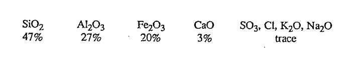
From a plant chemist’s viewpoint, this is a potent material in matters of clinker chemistry modification and must therefore be closely monitored and considered in mix calculations. Problems are magnified when the kiln switches back and forth between different types of fuels burned, e.g., when natural gas is fired part of the day and coal fired for the rest. Since natural gas does not contain the clinker modifying ash, the plant chemist must find a kiln-feed blend that is suitable for both types of fuel burning. It should be suitable from a burning as well as a quality-control viewpoint. In such instances, the resultant kiln-feed mix is a compromise at best. But, it is far better to compromise than to design a mix for coal firing and then switch to natural gas without making a mix adjustment The repercussions of such actions can be severe because the burnability of this kiln feed is drastically changed the moment the switch to natural gas is made. In this example, the kiln feed would be much harder to bum because the fluxing alumina and iron components in the coal ash would suddenly be absent A plant chemist of a precalciner plant must also give the same attention to the amount of ash that enters the system at the flash furnace.
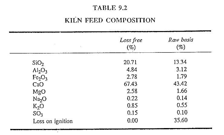
Now, it will be assumed that all these factors have been given due consideration by the chemist, and that the proper mix of different raw materials to obtain a typical kiln-feed composition (Table 9.2) is found. (Note: The chemical analysis below is used as the basis for all remaining discussions in this chapter. This analysis is only an example for illustrative purposes; every plant’s kiln feed will somehow deviate from the one shown below.)
The chemist now looks at the ash that enters the clinker and calculates what the theoretical clinker composition will be after the kiln feed has been burned and the ash included. Assume in this example that the clinker contains 3% coal ash:
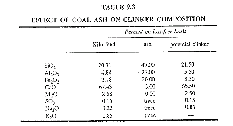
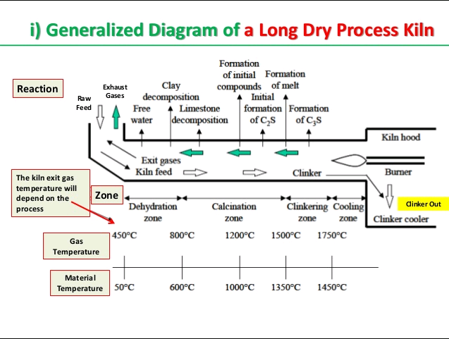
This clinker composition is only a preliminary potential wherein the actual composition of the clinker can vary due to the volatility of the alkalies and the sulfur. The important thing to remember is that, at this stage, there is not a material that has cementitious (hydraulic) properties. That is where the kiln comes in for it is here that this kiln feed is transformed into clinker minerals to obtain the ultimate properties of what is known as cement. During burning, this kiln feed forms the four main clinker compounds:
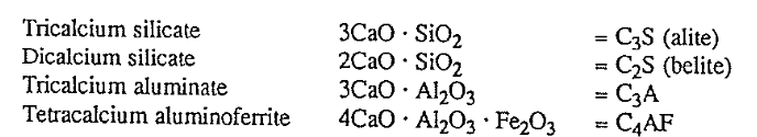
This compound composition is calculated with the help of the Bogue formulas, from the potential clinker analysis above (loss-free basis).
BOGUE FORMULAS FOR CLINKER AND CEMENT CONSTITUENTS
For a cement chemist, these formulas are the most important and frequently used indicators of the chemical properties of a cement or clinker. The constituents calculated by these formulas, however, are only the potential compositions when the clinker has been burned and cooled at given conditions. Changes in cooling rate or burning temperature can modify the true constituent composition to a considerable extent.
a)Bogue Formulas for Cement
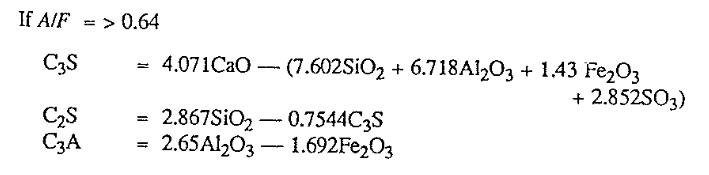
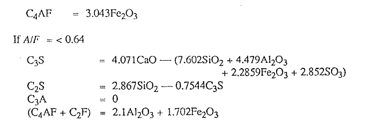
B) Bogue Formulas for Clinker Constituents.
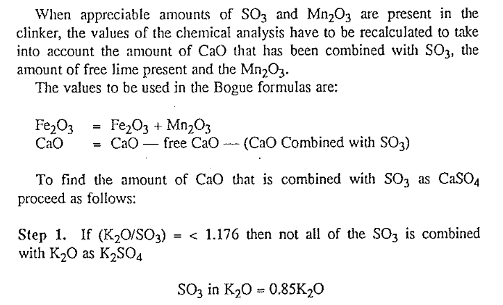
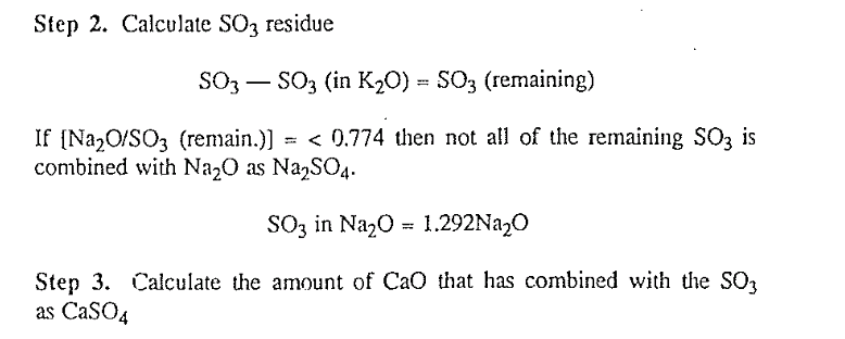

Having determined the appropriate values for the CaO and Fe203, one can then proceed to calculating the potential clinker constituents by using the previously given Bogue formulas. When the Bogue formulas are used for kiln feed compositions, keep in mind that the coal ash addition, dust losses, and alkali cycles can alter the final composition of the clinker. Also, it is necessary to use the analysis on a “loss-free” basis in the calculations of the constituents.
Tricalcium silicate is an important constituent as it is responsible main ly for early strength development of mortar and concrete. Regular portland cement kiln feed has usually a C3S potential of 52-62%. Kiln feed with a potential in excess of 65% is extremely difficult to bum and has a poor coating characteristic.
Dicalcium silicate accounts for approximately 22% of the clinker. Because a higher temperature is required to form C3S than CzS, under burning could result in a higher content of C2S and a lower content of c3s.
Tricalcium aluminate is responsible for the workability of the mortar. The higher the C3A content, the higher the plasticity (workability) of the mortar. This explains why kiln feed for the so-called plastic cements has a higher C3A potential than that for regular cement in which the C3A amounts to 6-8% of the clinker. Concrete containing cement high in C3A is not as resistant to attack by sulfates in soil or water exposure as is concrete made with low C3A cement.
Tetracalcium aluminoferrite governs the color of the cement The higher the content of CA4F in the clinker, the darker the cement This is undesirable, as users almost unanimously prefer a light-colored cement Iron has the desirable property of acting as a fluxing agent in the kiln, facilitating formation of other compounds of the cement at somewhat lower temperature than would otherwise be possible.
It is quite obvious that it is necessary to have a continuing analysis of the material going into the kiln, if there is going to be adequate control of the product coming out of the other end of the kiln. It is the respon sibility of the plant chemist to determine the composition of these materials and to proportion them to produce a kiln feed that ensures a uniform, high-quality clinker, combined with good bumability. Con tinuously uniform composition of the kiln feed is of greatest importance for proper operation of the kiln.
Various systems are employed to introduce the feed into the kiln depending on whether the wet or dry process is to be used. These systems all serve the same purpose: to feed the kiln at a steady and uniform rate with as little fluctuation as possible, which means that each raw material must be carefully metered or measured.
Using our examples above and the appropriate Bogue formulas, the following potential clinker compound content would be obtained:
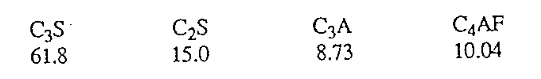
It must be again stressed here that the clinker compounds as calculated by the Bogue formulas are only potential in nature. Formation of these depends on the temperature, time of exposure, and cooling rate of the clinker in the burning zone and in actuality are quite different than the calculated values.
Up until now, a plant chemist has laid the foundation for the possible quality of the cement that will be produced from this clinker. But, his job doesn’t end here. It is his duty to reconcile this clinker with the burnability and coatability of this clinker. In other words, he not only has to concern himself with making a good quality cement but must also give due attention to the ease at which this clinker can be burned. Later in this chapter the microstructures of cement clinkers will be discussed and it will be shown that a plant chemist, in today’s cement technology, should and must also concern himself with the burning-zone environments that will ultimately affect the quality of cement.
INFLUENCE OF FEED COMPOSITION ON BURNABILITY
The “burnability” of a kiln feed is the relative ease or difficulty with which the feed is changed into a clinker in the kiln; that is, it is an indi cation of the amount of fuel required to bum the kiln feed into a clinker of good quality. Although it is highly desirable to produce at all times the same composition of kiln feed, this cannot readily be done. One reason is that most cement plants manufacture different types of cement such as high-early-strength, block and sulfate-resistant; therefore, composition of the kiln feed must change from time to time as different kinds of cement are being manufactured. Every time the feed composition changes, burnability in the kiln will also change.
A plant chemist, when calculating the kiln-feed composition, will employ certain formulas to ensure that the finished product meets the specifi cations of the type of portland cement to be made. Kiln-feed compositions are identified by a multitude of factors and indexes which are also used to express burnability. These are discussed briefly below.
Silica Ratio
The Silica Ratio is found by dividing the silica content by the sum of the contents of alumina and iron in the kiln-feed blend. That is,
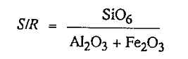
Increasing the silica ratio produces a clinker that is more difficult to burn; in other words, the clinker is “harder” to bum. It is mainly the content of alumina and ferric oxide that governs the combination of calcium and silica at lower sintering temperatures.
At this poin it is appropriate to define the terms “easy burning” and “hard burning.” In this text, an easy-burning kiln feed is one that requires less fuel to bum to a clinker than a hard-burning feed.
Alumina-Iron Ratio.
The Alumina-Iron Ratio is found by dividing the alumina content of the kiln feed by the iron content. That is,
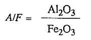
The higher the ratio, the harder the burning. Iron has a favorable influence on the speed of reaction between lime and silica; therefore, one can also say: Other values remaining constan a higher iron content leads to easier burning. Because both the numerator and denominator in the equation are expressions of fluxing componenls, however, the alumina alone is not used to express burnability.
This ratio indicates the quantity of initial liquid phase present during burning. It is generally accepted that an AIF ratio between 1.4-1.6 is a desirable optimum level and most beneficial to U1e burning of U1c clinker. The higher this ratio, the harder the clinker will be to burn.
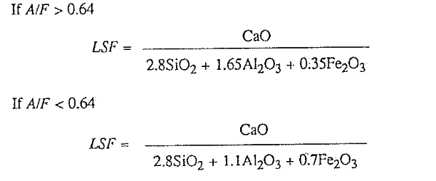
The Lime-Saturation Factor.
This factor has been used for kiln-feed control for many years in Europe and only recently has also found acceptance by American cement manufacturers. When the lime-saturation factor approaches unity, the clinker is difficult to burn and often shows excessively high free-lime contents. A clinker, showing a lime-saturation factor of 0.97 or higher approaches the· threshold of being “overlimed” wherein the free-lime content could remain at high levels regardless of how much more fuel the kiln operator is feeding to the kiln.
This lime-saturation factor when viewed in context with other indicators is an excellent indicator of what the free-lime content will be in the clinker when it has been burned at normal temperatures.
There have been instances in the past where a foreman, upon learning
from the lab results that the free-lime content was too high, approached the kiln bumer and asked him to bum the kiln hotter to lower the free lime It is true that lower burning zone temperatures deliver higher and, conversely, “hotter” kilns resulting in lower free lime in the clinker. Bu this is not the: only factor. High free lime can be associatd with too low a burning zone temperature only when the feed mix and the fuel burned remain unchanged; and. when the Iime saturation factor of the feed is below the so called saturation point. If for whatever reason the mix should suddenly show a lime-saturation factor of, e.g., 0.97 or higher, it would be very difficult for an operator to lower the resultant free lime by raising the burning-zone temperature. Such action most likely would do more harm to the coating and refractory than it would do any good to the clinker quality.
The opposite has also been observed where complaints were voiced to the kiln operator about burning the kiln too hot The reason given was that the free lime was consistently too low in the clinker. Again, a badly underlimed mix, having a lime saturation of less than 0.88, tends to deliver clinker that is low on free lime.
The point to remember is that when the free lime in the clinker is not up to standards, a check with the laboratory should be made first to see if the mix (lime-saturation factor) has changed. If this factor is still within normal ranges, then and only then, is there an indication that the kiln operator might not have burned the clinker at the proper temperature.
The permissible range of variation for free-lime contents varies among different plants but the majority of the plants attempts to obtain values that are between 0.4 and 1.2%. Experience has shown that when the clinker is burned as close as possible to the 0.8% level of free lime, the mix is then within acceptable levels.
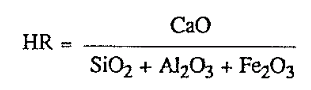
The Hydraulic Ratio.
The hydraulic ratio, developed by W. Michaelis over 100 years ago, is very seldom used any more in modern cement technology for kiln-feed control but is here included for plants that still regard this ratio as significant
Percent Liquid.
Clinker, when burned at 1450 C (2642 F) will be in a socalled semiliquid state. · This viscous appearance of the clinker bed is a very important control factor for a kiln operator when viewing the burning zone. This will be discussed in greater detail later on. The percent liquid is calculated by the Lea and Parker formula as follows:
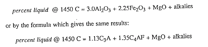
In both these formulas, the restriction applies that the MgO content is limited to a maximum of 2%. In other words, a value of not more than 2% MgO can be used in these formulas.
Most portland cement clinkers show a liquid content of 25-27.5%. Higher liquids produce stickier burning-zone clinker-bed appearances. Since the percent liquid as calculated by the above formulas applies to a temperature of 1450 C, higher temperatures give higher liquid and, conversely, lower temperatures result in lower contents of liquid in the clinker. Also, since alumina, iron, magnesia, and alkalies are fluxes, higher liquid contents make a clinker easier to burn.
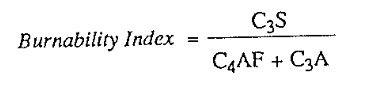
Burnabilty Index.
Kuehl’s bumability index is based on the potential clinker compounds C3S, C4AF, and C3A. The higher the content of C3S with corresponding lower contents in C4 AF or C3A, the harder the clinker is to burn.
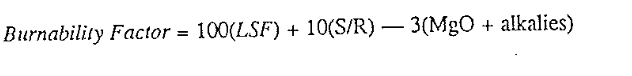
The Burnability Factor.
This factor was first introduced by this auth0r in the original Rotary Cement Kiln book. It was brought to the attention of the author that several chemists and engineers have made further research on the application potential of combining the lime-saturation factor with the silica ratio to express bumability. As mentioned in the original writeup, this formula was developed based on pure empirical notions and observations and, hence, was suspect in its fundamental reasoning.
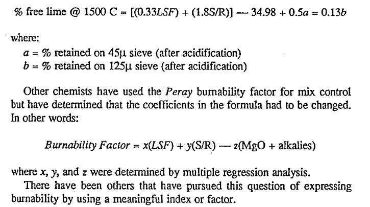
The laboratories of F.L. Smidth, Copenhagen, have recently presented their results of an investigation on this subject. Their findings are significant since they used scientific methods to arrive at a direct indicator of percent free lime in the clinker when the clinker is burned to 1500 C. The effect of alkalies and magnesia on burnability have been assumed constant in their formula, but due consideration was given to the effect of kiln-feed fineness on burnability. The FLS formula is:
Analysis of Burnability.
In addition to .the kiln-feed composition discussed above, the operator of a wet-process kiln has to consider also the moisture content of the kiln feed, as this indirectly affects burnability of the clinker. With unchanged composition of the kiln feed, a higher moisture content results in easier burning. The reason for the change in burnability is the simple fact that less feed is available to be burned when the moisture content is higher.
Because changes in kiln-feed composition have a large influence on kiln operation, it is important that the kiln operator be advised by the laboratory well in advance of any upcoming change in composition. Another good procedure is to note the chemical characteristics of the kiln feed every day in the kiln log.
So far only the influence of chemical properties on burnability in the kiln feed has been discussed. Plant operators must also pay attention to the kiln-feed fineness as these physical properties of the feed can influence burnability and the stability of the kiln operation. Since each plant produces clinker by using different raw materials and various types of kilns are in use, there are no clear cut standards in matters of kiln feed fineness that would apply to all kilns. There is, however, a consensus among operators that
- The coarse fractions in the kiln feed tend to be more significant than the finer fractions in their relationship to Hence, each plant needs to test for and specify the maximum limits of allowable fractions retained on the 30- or 50-mesh sieve (300, 500J.1 sizes respectively).
- The kiln feed has to be ground consistently uniform and with a little variations in particle-size distribution as possible on a daily
It is essential to make a clear distinction between a feed blend that tends to give a better visibility in the burning zone and a blend that requires less fuel to burn. Certain feed compositions create “dirty” conditions in the burning zone. Here a kiln operator could come to the wrong conclusion that because of the poor visibility the burning zone has cooled down. The action of raising the fuel rate in order to clear 01e burning zone could result in an overburned clinker.
On the other hand, another kiln-feed blend could possibly improve visibility in the burning zone. In such a case, a kiln operator could wrongly reduce the fuel rate because he concluded that the burning zone was warming up. The final result of his action could then be an underburned clinker.
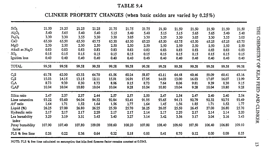
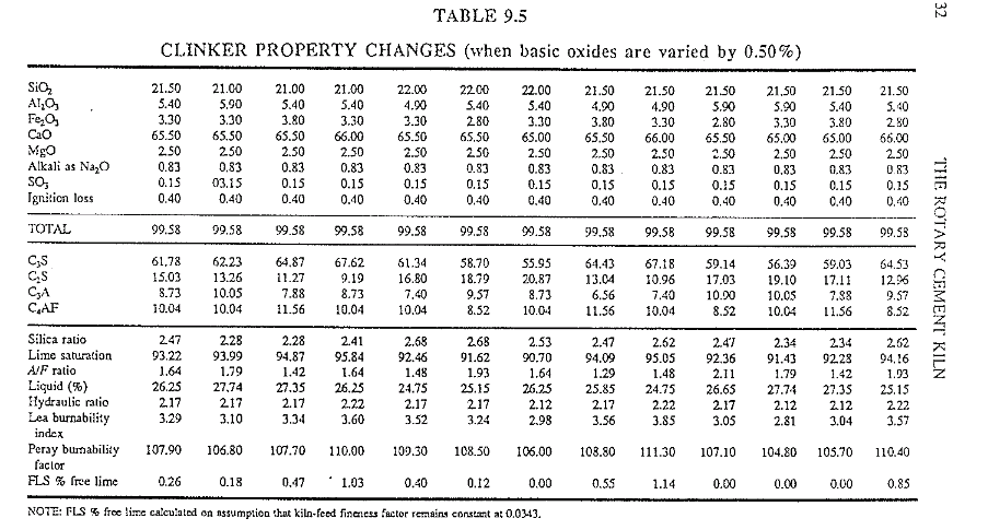
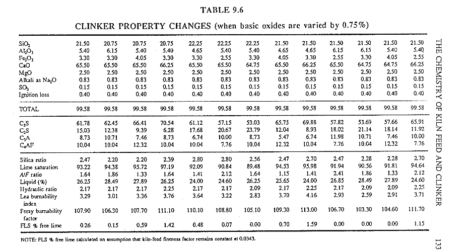
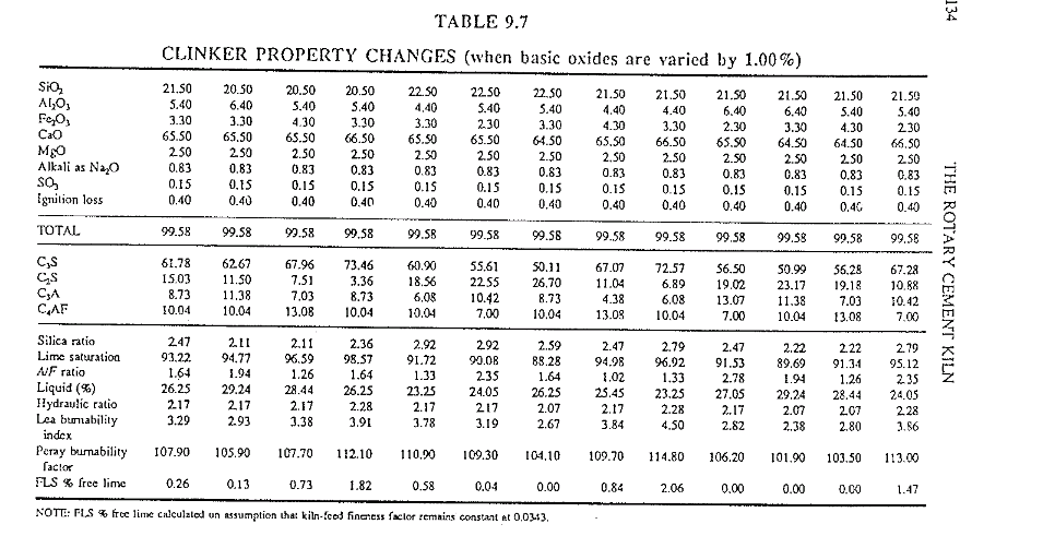
In Tables 9.4-9.7 the original potential clinker composition and the
various ratios and factors are computed. The percent free lime at 1500 Cis calculated using the F.L. Smidth formula but assuming that the kiln-feed fineness (45 and 125J.1 respectively) remains constant at 0.04 and 0.11 percent respectively.
For the purpose of illustration, changes of identical magnitude have been made in all four main oxides to show the reader how changes affect these various factors.
Several of the computed compositions are completely unacceptable in terms of burnability and clinker quality but they serve the purpose of familiarizing the reader with some of the intricate aspects of quality control.
Kiln-feed blends for production of special cement-clinker types such as high-early, sulfate-resistan !ow-alkali, and oilwell cement will all have somehow .different properties and chemical compositions. Changing from one type of clinker to another bum always requires special attention from the kiln operator and advice of such a change should be given well before this new feed is being used in the kiln.
The Liter-Weight Test.
One of the easiest tests a kiln operator can perform to learn if he has burned the clinker at the proper temperature is the liter-weight test. Free lime content also gives essentially the same information but analysis for free-lime content takes up to an hour until the results are reported. Since the sample is usually taken from the outlet of the cooler, the results tell what was done 1.5-2 h before which, from an operator’s viewpoin is not much help. In the liter-weight test, the sample is first passed through a 10- mm .screen then through a 5-mm screen. The fraction retained on the 5-mm.screen is then allowed to fall through a prescribed distance into a 1000- ml.container which is in the shape of a frustrum of a cone with the small end up. The weight of the clinker in this container, called the liter weight, indicates how well the clinker has been burned, as a hard-burned clinker has a higher liter weight than a soft-burned clinker, provided there is no change in raw-mix composition. A well-burned clinker has a liter weight between 1250-1350 g. The liter weight can vary considerably, even though the clinker is well burned, between one feed composition and another. If the raw-feed ·COmposition remains constant, the best clinker will have the appropriate liter weight and lowest free-lime content. The time required to run a liter-weight test is approximately 5 min.
Care must be taken to assure that the entire test procedure is carried out in the same consistent manner. From personal experience it better serves the operator to determine at what time the liter weight should be performed. In a well-running kiln, there is not much use in wasting time running a liter-weight test every hour. Liter-weight tests should be done when the operator or foreman is not quite sure if the clinker is being burned at the proper temperature.
Here, too, as with the free-lime tes there is the disadvantage of the time lag to consider since most samples are extracted from the cooler discharge. Some plants have overcome this by extracting the sample directly from the kiln hood before it falls into the cooler using careful cooling procedures to guard against burns.
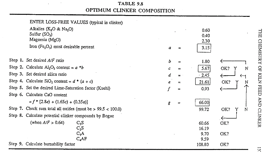
How many and what types of clinker indexes, factors, etc., are to be used for effective quality control is a matter that has to be decided by the operator and plant chemist. This author has used a backward approach to arrive at an optimum mix that theoretically would successfully produce a desired clinker. First, certain fixed desired properties like the lime-saturation factor, silica ratio, and AIF ratio are set and using these as constants the needed oxide composition is dived at. this method of opti \mum-mix design is very tedious when done by hand since it involves repeated trial-and-error calculations until the right suitable mix is reached. But, with the help of a computer program, this work is greatly simplified and quickly accomplished. An example using this procedure is shown in Table 9.8 In the preceding pages tile chemistry of the kiln feed and clinker have been extensively discussed. The novice reader should now have a fairly broad knowledge of the many problems and factors that are associated with making cement clinker in a kiln. For new kiln operators there will come a time when the realization that something is not quite right with tile mix occurs. It might suddenly happen while burning a problematic kiln feed. Sometimes these problems can persist for several days and a kiln operator can become frustrated. It is common for kiln operators, whenever the kiln doesn’t operate and handle properly, to blame these problems mistakenly on ti1e laboratory staff. In most instances this is not justified. It must be realized that the plant chemists face just as many obstacles as the kiln operator. Most of the time a chemist is aware that the mix is not up to his liking but he can do nothing about it because of many factors not · directly under his control. Raw materials might not be available to make appropriate corrections, kiln-feed reserves could be at low levels, or the raw grinding department might face it’s own disturbances.
In other instances the laboratory might get right back at the kiln operator and tell him that there is nothing wrong with the mix. The best way to guard against this type of stalemate is to establish a good dialogue between the laboratory and the kiln control room. A kiln operator can accept problems when they are explained. Being made aware of potential upcoming disturbances in the kiln is a more tolerable situation.
Assuming that the point has been reached where a shining clinker of superior quality has discharged from the cooler, the stage would be set for a good finished product. However, the cement as yet has not been produced. If just clinker alone is ground, the final product would be an inferior, unworkable cement. To control setting time, gypsum has to be added to the clinker during the finish-grinding process. Typical portland cement contains approximately 5% of gypsum.
At this stage, the production of cement, the binder that holds the sand and the a.ggreg::Hes in the concrete and mortar together, is completed. 1his is the most durable construction material that is known. No wood, glass, or steel construction will ever have the life span of concrete. The many things thnt were made of clinker serve as tributes to the kiln operator. An old, now retired kiln operator, told this author a few years ago that one of the most memorable things he did in life was to be involved in making the cement used for the construction of the Hoover Dam in Nevada .
. Considered at that time to be one of the eight technical wonders of the world, it is still around and doing well. What a monument to a kiln operator that had no automatic controller, no computers, no air-conditioned control room, and operated a kiln that was driven by a leather belt around the shell.
.
click here to Download the Most Important 13 Books in Cement Industry
click here to Download the Most Important 13 Books in Cement Industry
Please explain about the Rawmix desine.