Contents
EVERYTHING YOU NEED TO KNOW ABOUT ESTABLISHING CEMENT GRINDING PLANT 1MTY
THIS WAS FEASIBILITY STUDY MADE BY OUR COMPANY INFINITY FOR CEMENT EQUIPMENT IF YOU WANT ANY FEASIBILITY STUDY FOR 750 USD ONLY KINDLY CONTACT US ON
PROJECT DESCRIPTION
The present chapter describes the technical aspects of the clinker grinding plant, namely its capacity, imported raw materials, size and type of various equipment, storage of raw material and finished product, systems design, the plant layout and flow process.
Plant Capacity
The plant will have a capacity to produce 1.0 million tonnes of cement per annum (1.0 MTPA). Three different types of Portland cement1 will be produced in quantities dependent on market demands:
a) Ordinary Portland cement
This is a high strength cement grade manufactured to meet the needs of the consumer for higher strength concrete especially for specialized works, such as highway bridges, prestressed concrete and certain items of precast concrete structures requiring consistently high strength concrete.
b) Portland Composite Cement
It is a type of blended cement which is produced using pure calcite limestone. Portland Composite Cement makes concrete more impermeable and denser as compared to OPC, with advantages of higher degree of workability and reduced plastic shrinkage. The compressive strength at 28 days is equivalent to that of 42.5 R OPC.
c) Blast Furnace Slag Cement
This is a type of blended cement which is produced using granulated blast furnace slag and has similar advantages of higher degree of workability and reduced plastic shrinkage. The compressive strength at 28 days is equivalent to that of 42.5 R OPC.
Raw Material Requirement
The main raw material in terms of quantity will be clinker. This will be imported from the company’s own supply sources in India and China, and will not be manufactured on site in Mauritius. Clinker manufacture is a polluting process unsuitable for the Mauritian scenario, namely very restricted land space and the importance of its sectors like tourism which exacts a pristine island destination.
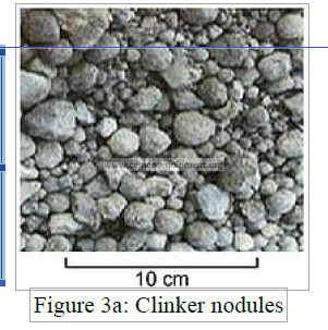
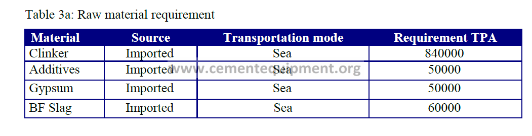
Table 3a indicates the general raw material requirement in tonnes per annum (TPA), based on a targeted output of 1.0 MTPA of cement comprising the 3 aforementioned grades.
Table 3a: Raw material requirement
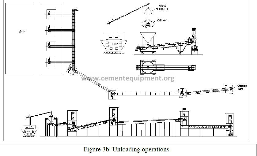
Unloading Operations
All the raw materials required for plant operations will be sourced from the company’s clinkering plants in China and India and will be transported overseas in bulk cargo vessels.
The vessels will carry clinker, additives, slag and gypsum in the same proportion in which they are expected to be consumed at the plant in Mauritius. Such dedicated vessels have wide experience in the loading, transportation and destination unloading of such materials, particularly with regard to pollution control regulations of their destinations.
Each vessel will be equipped with three to four Grab cranes capable of operating simultaneously during unloading operations (Ref. Appendix C on page 85).
The vessels will have a transportation capacity of 40-50000 metric tonnes (MT) equipped with four grab cranes of 30 MT capacities and a grab capacity of 12m3 each capable of unloading at a rate of 10-12,000 MT per day. Each vessel will thus, on an average take approximately about 4 days time for emptying. The hourly rate of emptying will be approximately 600 MT per hour.
Upon arrival of the vessel, four portable hoppers will be placed in position besides the vessel along the length of the quay. Each of these hoppers will have a capacity of 20 MT, suiting the grab capacity of the crane, and a gate at the bottom for controlled discharge. 800 mm width portable belt conveyors will be placed under each of these hoppers having a capacity of 350 MT per hour each.
The grab cranes will collect the material from the bulk cargo hold of the vessel and discharge it into the hoppers on the quay, from where the material will be fed onto the portable belt conveyors through the discharge gates. The portable belt conveyor will in turn discharge on to one of a series of belt conveyors leading up to the plant.
Once the unloading operations of the vessel are completed, the hoppers and the belt conveyors would be removed and stored at a suitable area so that the quay is available for normal operations.
Frequency of Vessels and Duration of Unloading
Based on the foregoing estimates and operations it is expected that two vessels on an average would be received in a month and the quay will be occupied for about 8 to10 days for raw material unloading operations.
Transportation from Quay to Plant
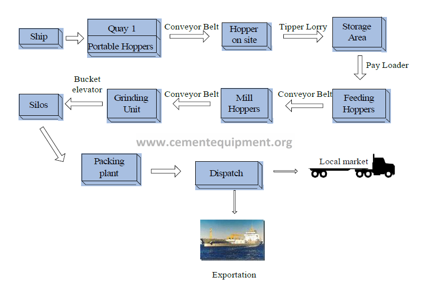
From the unloading portable hoppers on the quay (Quay I, Terminal II) the raw materials will be transported to the plant (up to a hopper on site) through a series of interconnected belt conveyor system with transfer from one belt to another
Block diagram indicating the steps of the process up to dispatch stage
A 1.0 metre wide belt conveyor with a capacity of 800 tonnes per hour (TPH) will be installed at one side of the quay. This belt conveyor which will be a permanent structure on one side of the Quay will be fed by the four portable belt conveyors as mentioned above and discharge onto another belt conveyor for takeoff to the plant. The belt conveyor will be designed in a manner so as not to obstruct the normal operations on the quay, whenever raw material of the plant is not being unloaded.
The takeoff conveying system will consist of a series of belt conveyors with transfer points in between, the route and elevation of which will depend upon the alignment of the belt conveyor from the quay to the plant, ground space available and possible obstructions and belt conveyor design considerations.
A preliminary study of the possible routes has been made and a possible route is indicated at Appendix C on page 87. The existing road from Quay I to the site (300 m) is quite wide and presents one possibility for the conveyor route.
However a detailed survey will be carried out so as to finalize the feasibility and design of the conveying system as there could be some obstructions on the proposed route.
All belt conveyors will be 1.0 m in width, having a capacity of transporting raw materials at the rate of 800 TPH and mounted on steel trestles and galleries. The galleries will be fully enclosed and each transfer point will be dedusted with high efficiency bags type dust filters (Ref. Appendix C on page 88 and 89)
The last conveyor in the series of belt conveyors will discharge into a steel hopper located inside the plant. The hopper will be enclosed and dedusted with high efficiency bags type dust filters. This hopper will have a gate for controlled discharge and will load onto tippers which will transport the material to their respective storage areas.
To check dust conveyors will be enclosed as far as would be practicable.
Storage of Raw Materials on Site
The areas for the storage of raw materials on site are shown in plan at Appendix C on page 90 and page 91.
The raw materials will be stored at two locations on the site; one for the clinker with a storage capacity of around 40,000 MT, and one for gypsum, slag and additives with a capacity of around 10,000 MT.
The drawing at Appendix C on page 88 illustrates the mode of material handling and storage when it arrives from the quay. A tipper lorry from under the unloading hopper will transport the material to the storage yard. Throughout the process all the hoppers of the clinker grinder plant (CGP) are equipped with efficient bag type dust collectors. This is elaborated in subsequent chapters of this Report.
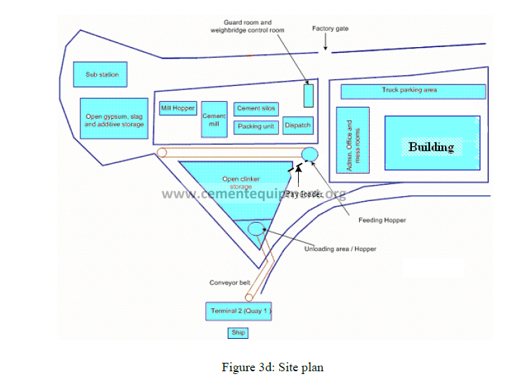
The raw material will be stockpiled and a pay loader will collect the material from the stockpiles to deliver it to the feeding hopper. The stockpiles would be around 6.0 to 7.0 metres high.
Whilst the raw material stockpiles will in the open, they will be covered with tarpaulins duly secured so as not to be blown away with gusty winds. Since the moisture content of the raw materials fed to the grinding mill must be controlled, the stockpiles must be covered so as to protect them from rain. This also eliminates windborne yard dust.
Additionally, a green belt cover will be developed around the periphery of the plant, so as to aid in arresting fugitive dust.
Raw Materials feeding
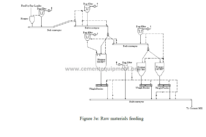
A feeding hopper will receive raw materials by pay loaders. A conveyor will next transport the material to the mill hoppers. The latter will comprise three hoppers handling clinker, gypsum and additive, in controlled quantities as shown in diagram above. The conveyor will then transport this mix of materials to the cement mill for grinding.
All hoppers and transfer points throughout the process will be enclosed and dedusted by high efficiency bag type filters, as indicated in the drawings appended to this Report.
Clinker Grinding Mill
The clinker, gypsum, and additive will next be fed into the grinding mill, to produce the desired type of cement. Essentially this is a rotating horizontal cylinder containing steel balls. The materials are crushed by impact and finely ground by attrition (friction) between the balls. Water sprays are passed through the mill to keep it cool since the high impacts produce heat and the cement temperature must be kept below 1000 C. The cooling water does not mix with the cement and therefore does not produce silt-laden effluents (Ref. Appendix C on page 93)
There are several types of grinding mills, and based on the best technical and economic options, for the present CGP a closed circuit ball mill has been chosen.
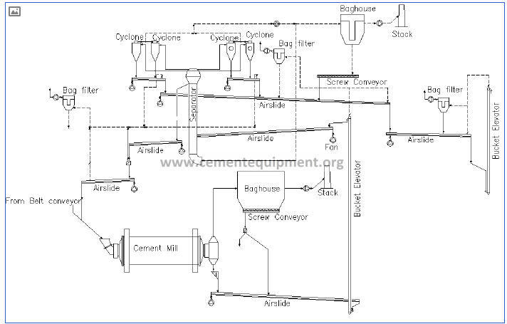
Figure 3f: Clinker grinding mill
The output from the mill produces both the required fine cement and partially ground coarse particles. A system incorporating an air separator through a bucket elevator and air slides separates the fine and coarse constituents. The coarse product will be returned back into the mill for further grinding.
The air separator will be provided with a dust filter in series into which the fines will be carried with the air stream, which will collect cement, the finished product.
The air from the cement mill will be dedusted in a bag filter before being vented out to the external environment.
The cement from the mill will be transported by a series of air slides and belt bucket elevator to the cement storage silos. As at the previous stages of the process, all the material transfer points and process venting will be dedusted with high efficiency bags type dust filters.
A clinker grinding plant (CGP) for the production of cement is in fact a blending process of finely ground clinker and additives. It is sometimes misunderstood for an integrated cement plant which also manufactures the clinker. The integrated plant process involves very high temperatures and the emission of high volumes of particulates and gaseous effluent. This is not the case for a straightforward CGP as in the present proposed project. The main energy input to the mill is the electrical power to drive the motors that rotate it. And the bag filters, which are known to be efficient, perform to the required emission standards.
Cement Storage
Cement from the mill will be transported by a system comprising air slides and a belt/chain bucket elevator to two storage silos each having a capacity of 5000 MT, and made of reinforced concrete. They will be equipped with aeration and extraction systems for cement discharge Ref. Appendix C on page 94.
One silo will contain ordinary Portland cement and the other blended cement. Discharge points from the silos will deliver cement to the packing plant and to the bulk discharge section. Dust emissions at discharge points are consistently checked by filter bags.
Cement packing
The packing plant will consist of a 16 spout Rotary Packer with double discharge having a bagging capacity of 4800 bags (50Kg each) or 240 MT of cement per hour. The entire operation of the packer will be electronically controlled, to ensure accuracy and consistency of weights in the individual cement bags (Ref. Appendix C on page 95).
Cement from the silos will be extracted through a series of air slides to the packer plant, where it will be fed to the packer hopper with an elevator and through a vibrating screen. The cement from the packer hopper will be fed to the rotary packer where it will be bagged into 50 Kg paper/HDPE bags.
The 50 Kg bags will be transported by a series of belt conveyors to semi automatic loading machines, one for each packing outlet. The loading machines will directly load the bags onto trucks for onward dispatch to the domestic markets.
For the export despatches, the 50 Kg bags will be stacked into 1.5/2.0 MT sling bags by making a 5X6 high stack and wrapping the sling around the stack. Higher or lower capacity slings depending upon market/customer requirement can also be used in a similar manner.
The packing plant will be equipped with two high efficiency bags type dust collectors for process venting and dedusting of all transfer points.
Cement Dispatch
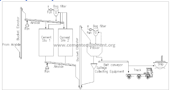
Figure 3g: Cement packing and dispatch stages
Cement for the domestic market will be either packed in 50 kg bags or loaded directly onto trucks for dispatch to warehouses/customers or will be loaded onto bulkers for dispatch of bulk cement to domestic customers, depending upon requirements.
It is envisaged that cement for the export markets will generally be required to be shipped either in 50 kg bags, or 50 kg bags packed in jumbo bags of 1.5/2.0 MT capacity or in bulk. All these modes of dispatch would require different handling methods from the plant to the Quay.
A belt conveyor system is proposed to be installed to transport 50 kg cement bags from the plant to the Quay 3. A suitable arrangement will be provided for handling the bags, to enable for an optimized loading system into the ships.
The proposed route is tentatively indicated at Appendix C and this would be finalised after detailed surveys.
The sling bags, which will be packed in the plant and stored in a covered shed with a capacity to store and handle about 10000 MT, will be transported by trucks to the Quay and will be loaded onto the ships by their cranes.
Pipelines through which cement will be pneumatically conveyed from the plant to the Quay 1 (or possibly Quay 3) along the same route as the conveyors has also been considered and provided for.
Plant System and Machinery
All plant items and machinery will be acquired from suppliers reputed for their experience, high global standards of workmanship and state of the art technology. The clinker grinding plant would thus be ensured of its eco-friendly performance and compliance with environmental standards.
All the handling operations of raw materials are proposed to be carried out on local contract. These will include loading and unloading of raw materials and cement into trucks/tippers, handling during storage, feeding from storage and transportation within the plant and from the plant to the Port.
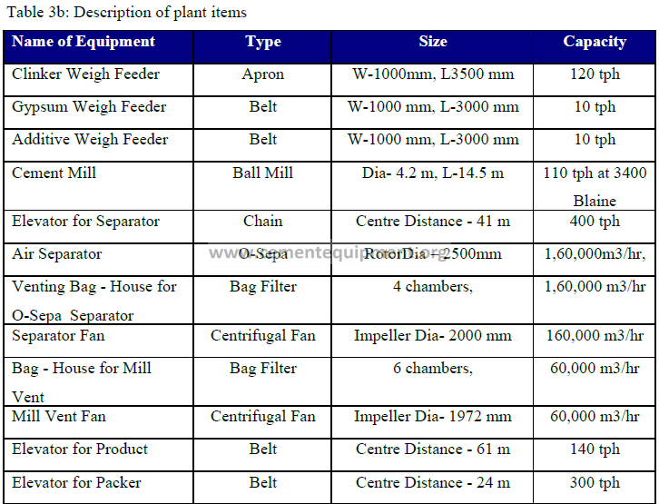
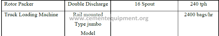
A broad description of the plant items to be used is listed in Table 3b. Their selections are based on reliability and matching capacities between different sections of the plant. Certain items are indicative and may be changed at detailed design stages.
Storage Capacities
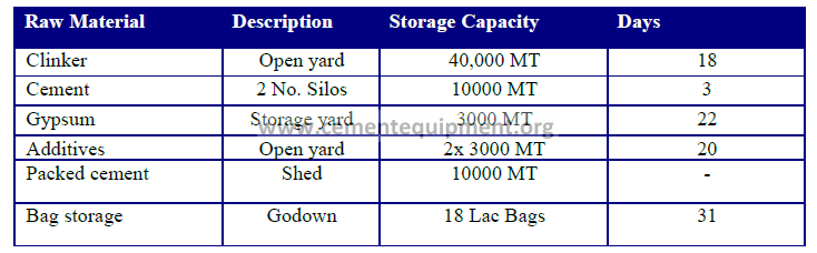
The storage capacity of the proposed plant for the respective raw materials and finished goods are indicated in Table 3c.
Table 3c: Storage capacities
Quality Control
The proposed plant will comprise a modern, technologically advanced laboratory to ensure the quality control of its finished products and maintain the high standards which the company aims at worldwide.
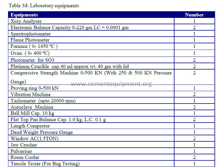
Highly accurate weighing systems will be used for controlling input materials to the cement mill, and for ensuring uniform and constant plant operations. These are essential requirements for maintaining sound and uniform quality cement. The laboratory will include the following equipment shown in Table 3d.
Water Requirements
The total daily requirement of water for the proposed plant is estimated to be 125 cubic metres as shown in Table 3e
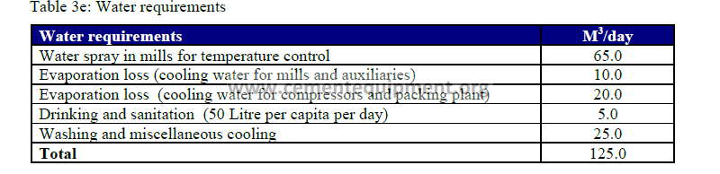
The water requirement of the plant shall be met from the existing water supply network of the harbour area. The water storage capacity at the plant will meet the requirements for 3 days.
Electricity Supply
Ref. Appendix C on page 96 for electrical details in single line diagram
The power demand of the proposed plant is estimated at around 5.5 MW. The Table 3f illustrates the power requirement for producing one tonne of cement. General specifications of E&I equipment, machinery and systems are at Appendix C on page 97.
Table 3f: Power requirement to produce 1 Ton of cement
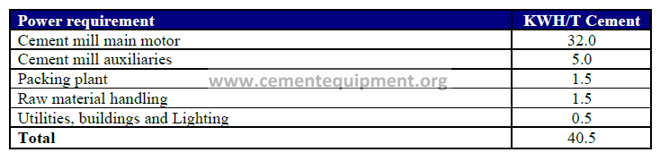
Basically, the plant will have a total connected load of about 6.25 MW and an average operating power of 4.5 MW. Fort George power station (Central Electricity Board) has sufficient surplus capacity to meet the power demands of the proposed plant, and arrangements will be made with the Central Electricity Board to finalise the supply modalities.
Power supply to the plant will require the following:
1. Extension work at the power station relating to dedicated power feeding to the plant.
2. Laying of 22 kV High voltage (HV) underground cables from the power station to the plant
3. Installation of HV metering switch gear panels.
Salient power features that would be incorporated to ensure safety, energy efficiency and conservation will include:
• Intelligent power and motor control centres.
• Power factor improvement
• Double earthing and lightning conductor for the entire plant
• Power saving variable voltage/frequency drives
• Emergency push buttons and pull cord switches
• Appropriate lighting levels in all areas in conformity with norms
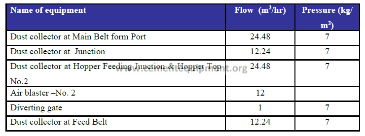
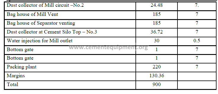
Compressed Air Requirement
The overall compressed air consumption of the plant is estimated to be 900m3/hr as laid out in Table 3g. To provide this requirement the plant will have 2 screw compressors (one standby), each of capacity 926m3/hr.
Table 3g: Compressed air requirement
Working Hours of the Plant
The viability of the proposed clinker grinding plant rests on its output volume (1.0 MTPA of cement) and several economies of scale, as laid out at Section 1.3 which elaborates the Economic Feasibility of the project.
The hours of unloading and storage of raw materials would be dictated by ship arrival schedules, as in most similar industrial sectors.
The cement production would be dictated by local and foreign demands, and, by the targeted 1.0 MTPA. Grinding operations would therefore necessarily be carried out 24 hours a day through three eight hour shifts for 365 days a year.
The packing plant is planned to operate 24 hours a day through three 8-hour shifts, 365 days a year. Although this may vary according to market requirements, it is not expected to fluctuate significantly. The port is manned 24 hours, 7 days a week, and 365 days a year. Bulk cargo vessels operate on a 3-shift basis round the clock, at the MPT from Monday to Saturday, and one shift on Sundays and public holidays.
THIS WAS FEASIBILITY STUDY MADE BY OUR COMPANY INFINITY FOR CEMENT EQUIPMENT IF YOU WANT ANY FEASIBILITY STUDY FOR 750 USD ONLY KINDLY CONTACT US ON CONSULTANTS@CEMENTEQUIPMENT.ORG
It caught my attention when you said that cement from silos is being extracted through a series of air slides to the packer plant during the process of cement packing. This reminded me of the process of cement manufacturing where air cannons should be used to solve blockage and buildup issues within coolers. I could imagine how this could help many other industries to ensure smooth operations.