Contents
EVERYTHING YOU NEED TO KNOW ABOUT BAG FILTERS ” EXCELLENT COMPREHENSIVE GUIDE “
A: Introduction – Baghouse Dust Collectors
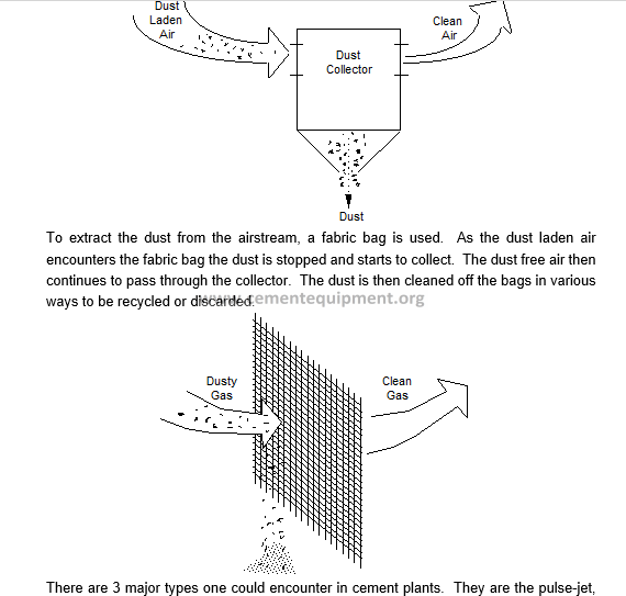
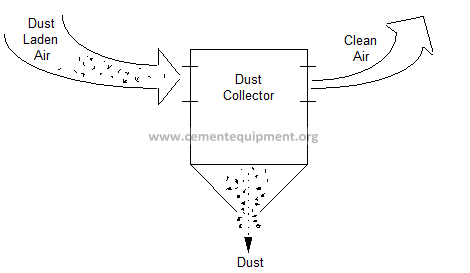
A baghouse dust collector is a simple but efficient device designed to extract dust particles from an airstream and to collect those particles in order to recycle or discard them.
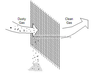
To extract the dust from the airstream, a fabric bag is used. As the dust laden air encounters the fabric bag the dust is stopped and starts to collect. The dust free air then continues to pass through the collector. The dust is then cleaned off the bags in various ways to be recycled or discarded.
There are 3 major types one could encounter in cement plants. They are the pulse-jet, reverse-air and shaker. The shaker is a collector which mechanically shakes the bags clean. These are becoming rare and therefore will not be discussed.
A1 Description and characteristics – Pulse jet collector
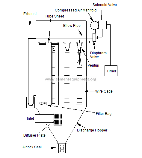
A pulse jet collector (figure 1) typically consists of a one compartment bag house with a specific number and size of bags. The number and size of bags depends on the area to be vented. An I.D. fan provides the air flow. A tube sheet which divides the collector into an upper and lower section, a blow pipe cleaning mechanism and diaphragm valves that are controlled by an electronic control module. This type uses blasts or pulses of compressed air to clean the bags.
A1.1 Tube Sheet and Bags
The upper and lower halves are divided by the tube sheet, which also serves as the mounting plate for the collector bags. The upper half is the clean air side and the lower half is the dirty air side. In the pulse jet collector the bags are suspended from the tube sheet. A snap band is designed into the bag to hold the bag in place, (different suppliers will have different designs). A wire cage is installed inside the bag to prevent if from collapsing inward. Especially on older models (pre 1990), the clamping method to the tube sheet is the weakest point in the design. Many leaks occur here. Newer designs pay a lot of attention to reinforcing this area.
Dirt laden air is drawn into the collector by the air flow created by the I.D. fan. The dirty air enters in the lower half of the collector and is cleaned as it is drawn up and through the bags. As the dirt is collected on the outside of the bags it forms a dust cake. As the cake builds up on the bag it creates an air flow resistance, and for this reason the bags need to be cleaned.
The baffle plate is important since it is there to knock down as much dust as possible before reaching the bags. It will also help prevent the incoming dusty air from wearing holes in the bags nearest the intake.
Close attention should be paid the assembly quality or condition of the cages. Burrs, sharp edges, weld flashings, etc. will quickly abrade holes in the bags.
Bags are usually made from polyester, glass or Gortex felts. Felts normally work best in pulse-jet collectors and can be supplied with a variety of surface treatments (teflon, singed, etc.). The type best to used depends of the temperature, dust type, duty and dust loading. Note it is strongly recommended for bags used in fuel system dust collectors that they have a grounding wire sewn into them.
A1.2 Differential Pressure
This resistance is measured between the top and the bottom of the tube sheet and is called Differential Pressure or D.P. There are three types of devices used here in the plant to measure the D.P. One of the devices used to measure D.P. is called a magnehelic. It is located on the side of the collector near the tube sheet level. A copper tube goes from one outlet of the magnehelic to the upper side of the tube sheet, while another goes from the magnehelic to the lower side of the tube sheet. The difference between the two sides or the resistance to air flow is calculated and gives the D.P., or the pressure drop across the tube sheet.
The second type is called a photohelic. It is located adjacent to the magnehelic, but is capable of controlling the D.P., by setting a high and low point. The general range is 2″ low and 6″ high. What this does is keeps a constant measure of the D.P. and starts the cleaning cycle by activating the electronic control module. As the D.P. reaches the high set point it activates the control module, this is turn starts the cleaning cycle. It continues to clean until the D.P. reaches the low set point at which time it shuts off the controller. Once it is initiated, rows of bags are sequentially pulsed until all rows have been cleaned. This system is particularly useful in minimizing compressed air consumption and increasing bag life. However it is not recommended for use on units where the fan must regulate a pressure setpoint.
The third type of is an electronic differential pressure regulator. This does the same job as the photohelic but has no gauge or visible way to read or change the set points. The set points are pre-set by the electronics department in the plant.
Ideally the differential pressure across a dust collector should be about 4″ WC. However one should check with the manufacturer if a particular unit is rated differently.
A1.3 Cleaning Process
The electronic control module activates a diaphragm valve which sends a pulse of compressed air through the blow pipe. Between the diaphragm valve and the control module is a copper or plastic bleed off tube, which allows pressure to equalize between the diaphragm valve and the control module. Once the pressure has equalized the diaphragm releases and sends a blast of compressed air down the blow pipe.
The blow pipe is placed in line at a horizontal position typically about four inches above the row of bags. The blow pipe has a hole about 1/4 to 3/8th’s of an inch in diameter located over the center of each bag, (this depends on the design). The top of the wire basket has a venturi in it. As the pulse of air enters the venturi it draws in some surrounding air. This is referred to as induced secondary air. The duration of the pulse is approximately 1/10th of a second, and the effect is that of shock rather than bag inflation. One can observe this as a bulge which travels with the shock wave. When the shock impacts the bag, most of the dust cake is knocked loose and begins to fall toward the bottom of the collector, but since the duration of the shock is so short, the dust returns to the outside of the bag, only after it has fallen just a few inches. The dust near the bottom of the bag falls into the discharge hopper and is either returned to the system or discarded. An air seal device is located at the discharge point to prevent outside air from entering into the collector.
Note, it is a common but mistaken belief that pulsing the dust collector after the system is down will purge the dust collector bags clean. If the fan is off, some dust may fall off after the first pulse but it has been shown that very little will come off afterwards. To purge a pulse jet dust collector the fan must be left running while the collector pulses. The normal air flow holds the bag against the cage which allows the shock wave to bulge the bag. This is the most effective cleaning.
Air pressure is very important because it is the force that cleans the bags. The amount of pressure required depends to some extent on the specific application, fineness of dust, density, etc., but for most applications the minimum pressure is 90 PSI. This compressed air is also dried by an air dryer which is located between the compressor and the collector. The compressed air used must be dry otherwise moisture can cause dust to cling and blind the bags.
A1.4 Process Notes
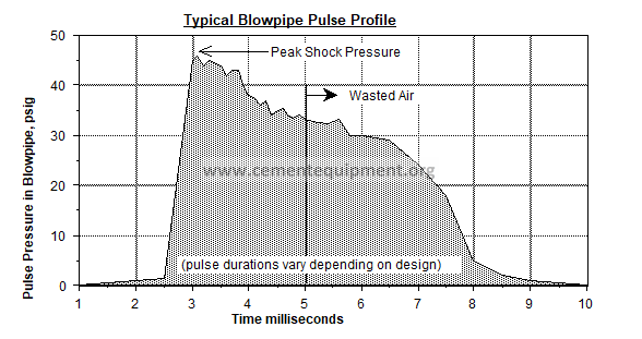
Most early models of the Pulse-jet dust collector were not well designed. Often they were not sized correctly and as a result many plants experience problems with not being able to get enough gas flow through the dust collector and the differential pressures were always high (10 to 12 inwc). Usually the problem is that there is too much dust (per unit volume of gas) and the collector cannot pulse the bags sufficiently clean. As mentioned already it is important to maintain a minimum air supply pressure of at least 90 psi. Really effective cleaning comes from getting the largest possible shock. The induced secondary air purge helps some but on early models it really doesn’t do much, (this is reportedly much better on the latest but very expensive models). The following graph shows a typical pulse pressure profile as measured in the blow pipe. The best shock and hence cleaning occurs by attaining the highest peak pressure in the shortest time. At the very minimum this should be 40 psi although 60 to 70 is more ideal (for 100 psi air supply pressure). The rest of the pulse draws in purge air through the venturi but as mentioned, on early models, this is wasted compressed air. Since most units come equipped with electronic solenoid timers, it is possible to adjust the pulse span. This should be adjusted to get the sharpest “thud” but no more. If you have a new model check to see where the pulse length should be set. Also the frequency of pulsing can be adjusted to get more or less cleaning. Too high of a setting just wastes compressed air.
How to get more cleaning (and more flow through the dust collector)
- a) Check that the cross sectional area of the blowpipe is greater than or equal to the sum of the area of all holes in each blowpipe. If it is less then the cleaning shock will be too low. You can increase this ratio to get better cleaning but only up to a point, (which = supply pressure – pressure losses across fittings).
- b) Check that all fittings and valves feeding compressed air into the blowpipe are larger than the blowpipe diameter. The larger the better since the pressure loss across these fittings can be very high. Any restrictions will drop the shock pressure.
- c) Occasionally the venturis must be replaced due to wear. Be sure that the replacement has the largest possible throat diameter. (different suppliers will give you venturis that fit your cages but have different throat diameters). The smaller the throat, the smaller the cleaning shock pressure and the higher the resistance to normal flow.
For example at one plant the dust collector was using blowpipes made from standard 3/4″ sched. 40 pipe and each were fitted with a 1/2″ shutoff valve. Changing the valve to 3/4″ improved cleaning which allowed them to increase airflow by 8%. Then they took the step of changing the blowpipe size to 1″ dia. as well as the diaphragm valves, shutoff valves, couplings, nipples etc. Cleaning improved again and they were able to increase airflow by another 10%.
New designs, we have observed employ 6″ diaphragm valves feeding 2″ diameter blowpipes and double venturis. The venturi fitted to the cage is the same diameter less the thickness of the metal casting, (in other words it has the largest possible throat). Cleaning is claimed to be so much more effective that plants are able to reduce compressed air requirements.
A1.5 Troubleshooting – Pulse jet collector
Condition: Dirty exhaust air
- Through compartment windows observe top of tube sheet for evidence of dust leaking through bags or holes in tube sheet or around the venturi where it is fastened to the tube sheet. Notify condition and location to Mechanical Maintenance.
Condition: High D.P. noted
- Check main air supply and dryer for proper operation. If not O.K. refer to equipment troubleshooting guide.
- If O.K. check air pressure at manifold, which should be 90-100 PSI. If the PSI is to low, check for leaks in the air lines. If leak is located attempt to repair or notify Mechanical Maintenance.
- If no leaks are located, check for sticking solenoid or defective diaphragm valves. If noted, isolate defective unit and notify mechanical maintenance of location and condition.
If no air loss noted on this collector, check remaining collector systems. (Cleaning air comes from a common air supply). Also observe for high D.P. on these collectors and continue to check for leaks in the system until located. Repair if possible, if not possible notify mechanical maintenance.
Condition: High D.P. – System air supply O.K.
- Check to make sure collector is cleaning properly, if cycling not to specs. Notify electrical maintenance.
- If cycling O.K. check collector discharge and tipping valve for plugging condition (air slide, screw or rotary feeder). If plugged refer to related troubleshooting guide. Check collector fan dampers for proper operation.
- If dampers not operating properly and you are not able to repair, notify electrical or mechanical maintenance of the problem.
Condition: Low D.P.
- Make sure all doors are closed and there are no holes in the piping.
A1.6 Safety – Pulse jet collector
- Never work inside a collector without another employee present.
- Make sure related equipment is locked out or turned off, such as fans, collector screw if equipped, compressed air supply and rotary feeders and dampers.
- Use respirators and goggles when necessary.
A1.7 Walk through inspection – Pulse jet collector
- Check collector vent stack for dust emissions; there should be none.
- Look through the windows (where applicable), installed on the clean air side of the collectors that have them, for dusty conditions.
- Check the D.P. gauge; it should read between 2″ and 6″.
- Listen for air leaks along the solenoid valve manifold.
- Listen to the solenoid valve (s) go through the pulse cycle, to ensure that all valves are working properly.
- Check the pulsing air pressure; it should be no lower that 90 PSI.
- Check for leaks around doors, seams and on the piping.
- Check discharge hopper points for leaks around the air seal.
A2 Description and characteristics – Reverse air collector
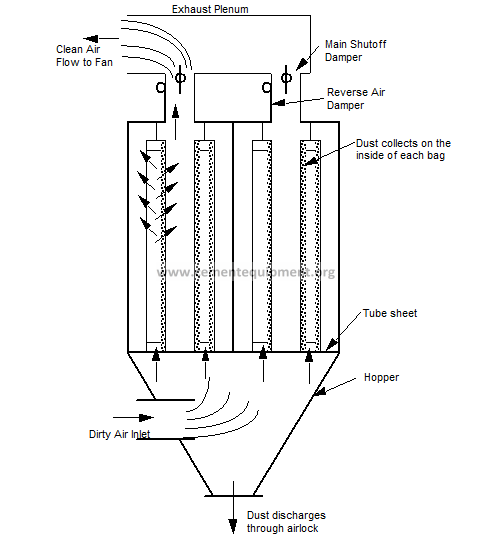
A reverse air collector (figure 1) consists of a bag house containing two or more compartments each fitted with an equal number of bags. Size and quantity of bags depends on the amount of venting to be done. An I.D. fan creates the air flow, and a tube sheet which divides the collector into an upper and lower half. Dampers are in place to direct air flow, and a timer to control the dampers operations. Discharge hopper or hoppers with various mechanisms to take dust away, and an air seal to prevent outside air from entering the collector through the discharge end.
A2.1 Tube sheet and bags
The I.D. fan creates the air movement through the collector and the duct work. The tube sheet which divides the collector in half also serves as the mounting plate for the bags. The upper half which contains the bags is also known as the clean air side and the lower half is know as the dirty air side. The open end of the bag is attached to the tube sheet with metal clamps. The opposite end is then hooked and suspended from the top of the compartment with a chain and spring assembly. The tension is set so that the bag will remain upright and retain its shape.
Woven bags are generally preferred in reverse air units. They come in a variety materials depending on application such as polyester, glass and Gortex.
A2.2 Collector Operation
Two dampers are used on each compartment to direct air flow. When the main damper opens the reverse air damper is closed. This puts the compartment under negative pressure. The air flow entering the collector is dust laden and is drawn up through the tube sheet and the bags. The dust is filtered out by the bags and the clean air exits the collector through the main damper (figure 1). During the cleaning cycle the main damper closes, this puts the compartment at a neutral state allowing trapped dust to start falling out of the bags. Then the reverse air damper opens and the air is reversed which starts to shake the bags and dislodges the remaining dust, (backflushes with air). This dust is drawn out of the bags with the air flow and falls into the collector hopper. The dust in then discharged by various ways and put back into the system (figure 2).
Since whole compartments at a time are purged clean, reverse air units will be much larger than pulse jet units processing the same amount of gas.
Fig. 1: Reverse air collector
An air seal of various sorts is located at the discharge point to keep outside air from flowing back into the collector. The cleaning cycle is repeated on each compartment until the entire collector has been cleaned and then repeats over and over. Only one compartment at a time should be cleaning.
A2.3 Compartment Isolation
Some larger units are designed with each compartment having an isolation switch. This switch is normally located in the vicinity of the compartment door. The switch takes the compartment out of the cycling mode. This closes the main damper and opens the reverse air damper. It isolates the compartment so it can be inspected and worked on.
A2.4 Trouble shooting – Reverse air collector
Condition: Not venting properly
- Check for proper draw. If not proper, check duct work for plugging conditions and clean obstruction.
- If not plugged, check fan for proper operation, refer to fan troubleshooting guide.
- Fan’s operational – check collector hopper. If full, check discharge screw to inspect if running properly, or refer to screw troubleshooting guide.
- Hopper’s okay, screw running, but collector still not venting; check off/on switch for each compartment – inspect tagged compartments.
Open compartment doors for visual inspection – seam leaks in the tube sheet; dirt build-up on the tube sheet; down, ripped or full bags. If needed, shake bags down. If unable to clean bags or bags are down or ripped, shut compartment off and notify mechanical maintenance.
- Compartments visual check is okay; check collector cycling, dampers stuck, i.e. one or more dampers open all the time.
- If stuck, free up.
- Check motor (or pneumatic cylinder) and linkage on each damper for proper operation or damper cycle.
- If timer not working properly or a motor will not operate. Contact electrical maintenance.
Condition: Collector exhausting dust – steps 3, 4. 5.
Condition: Collector pressurized – steps 5, 4, 3.
If all of the above check out okay, notify mechanical maintenance to check bag permeability or process technician to check collector pressure drop.
A2.5 Safety items – reverse air collector
- Never work inside a collector without another employee present.
- Make sure related equipment is locked out or turned off, such as fan, collection screw if equipped, compressed air supply, rotary feeder and dampers.
- Use respirators and goggles when necessary.
A2.7 Walk through inspection:
- Check discharge air to make sure it is clean.
- Check dampers to ensure proper cycling.
- Check duct work for leaks and holes.
- Look and listen for air leaks around the doors.
- Check fan for vibration, unusual noise, air leaks, worn drive components and hot or bad bearings.
Dust collector and bag filters can be more complicated than I thought. I did not know there were 3 main types. Hunting down a dust collector inspection service might be wise because there are more components that make things more confusing for the novice.