Contents
EVERY SINGLE EQUATION IN CEMENT INDUSTRY
[wpecpp name=”package + Updates forever” price=”250″ align=”center”]

P A R T I
CEMENT CHEMISTRY
Chapter 1
QUALITY CONTROL FORMULAS
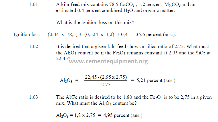
1.01 Ignition Loss
Ignition loss is usually determined by tests in a laboratory furnace. It can also be
calculated from the chemical analysis of the kiln feed by the following formula:

1.02 Silica Ratio
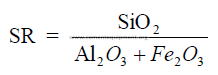
Large variations of the silica ratio in the clinker can be an indication of poor
uniformity in the kiln feed or the fired coal. Changes in coating formation in the burning zone,
burnability of the clinker, and ring formations within the kiln can often be traced to changes
of the silica ratio in the clinker. As a rule, clinker with a high silica ratio is more difficult to
burn and exhibits poor coating properties. Low silica ratios often lead to ring formations and
low early strength (3 – 7 days) in the cement.
1.03 Alumina – Iron Ratio
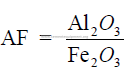
Clinker with a high alumina – iron ratio, as a rule, produce cement with high early
strength (1 to 3 days) but makes the reaction between the silica and calcium oxide in the
burning zone more difficult.
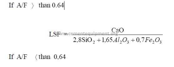
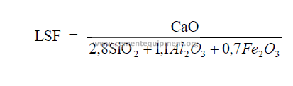
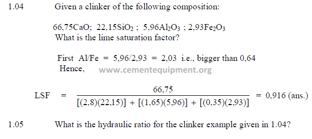
1.04 Lime Saturation Factor
This factor has been used for kiln feed control for many years in Europe and only
recently has also found acceptance by American cement manufactures. When the lime
saturation factor approaches unity, the clinker is difficult to burn and often shows excessive
high free lime contents. A clinker, showing a lime saturation factor of 0,97 or higher
approaches the threshold of being “overlimed” wherein the free lime content could remain at
high levels regardless of how much more fuel the kiln operator is feeding to the kiln.
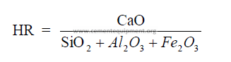
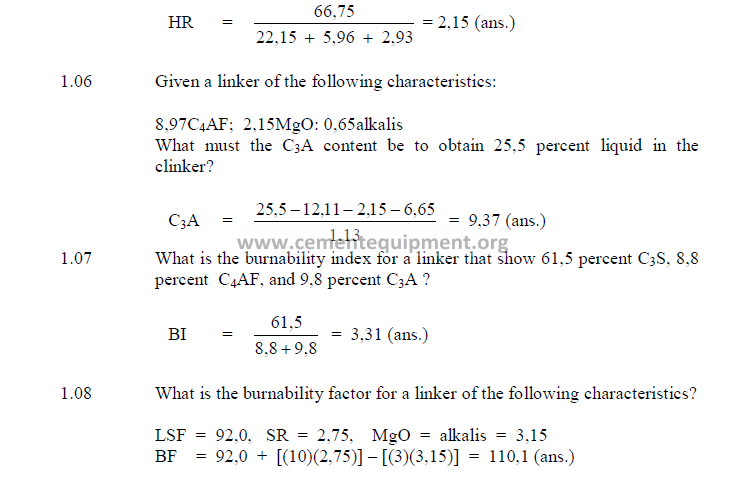
1.05 Hydraulic Ratio
This index is very seldom used any more in modern cement technology for kiln feed
control.
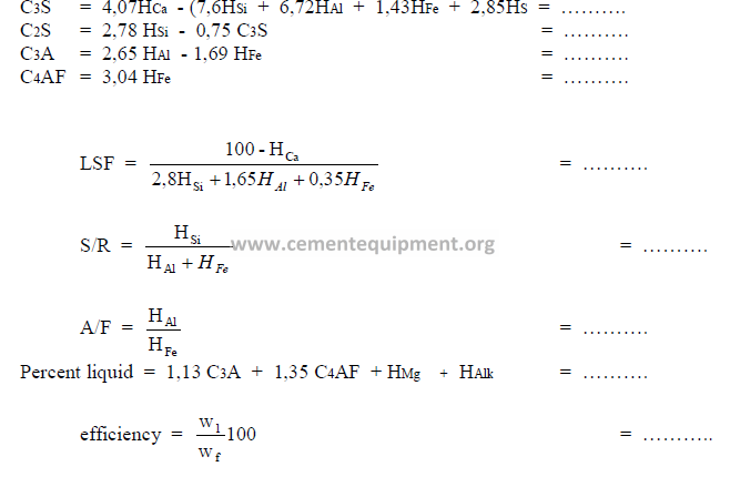
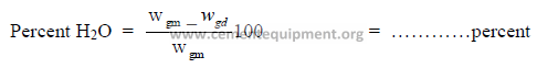
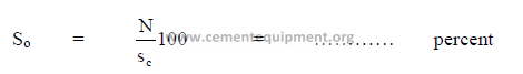
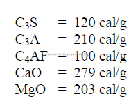
1.06 Percent Liquid
Clinker, when burned at a temperature of 1450ºC, Has the following liquid content:
![]()
![]()
1.07 Burn ability Index
This is an indicator of the ease of burning for a given clinker. The higher the index
number, the harder the clinker is to burn.
BF = LSF +10SR – 3(MgO + Alkalis)
(find LSF in 1.04 and SR in 1.02)
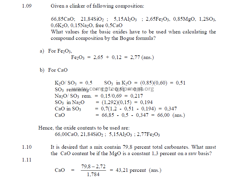
1.09 Bogue’s Formulas for Clinker and Cement Constituents
For a cement chemist, these formulas are the most important and frequently used
indicators of the chemical properties of a cement or clinker. The constituents calculated by
these formulas, however, are only the potential compositions when the clinker has been
burned and cooled at given conditions. Changes in cooling rate or burning temperature can
modify the true constituent composition to a considerable extent.
a) Bogue’s Formulas for Cement Constituents
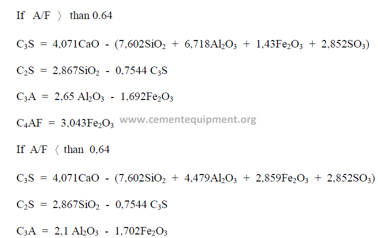
b) Bogue Formulas for Clinker Constituents
When appreciable amounts of SO3 and Mn2O3 are present in the clinker, the values of
the chemical analysis have to be recalculated to take into account the amount of CaO that has
been combined with SO3, the amount of free lime present and the Mn2O3.
The values to be used in the Bogue formulas are:

To find the amount of CaO that is combined with SO3 as CaSO4 proceed as follows:
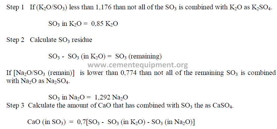
Having determined the appropriate values for the CaO and Fe2O3, one can then
proceed to calculating the potential clinker constituents by using the previously given Bogue
formulas. When the Bogue formulas are used for feed compositions, keep in mind that the
coal ash addition, dust losses, and alkali cycles can alter the final composition of the clinker.
Also use the analysis on a “loss free” basis in the calculations of the constituents.
1.10 Total Carbonates
Total carbonates are usually determined analytically by the acid-alkali titration
method. They can also be calculated from the raw (unignited) analysis as follows:
![]()
![]()
1.11 Total Alkalis as Na2O
The total alkali content in terms of sodium oxide is calculated from the loss free
analysis:
![]()
![]()
1.12 Conversion of Raw Analysis to Loss Free Basis
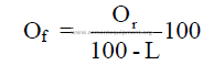
where
Or = percent of oxide (by weight) on a raw basis
Of = percent of oxide (by weight) on loss free basis
L = percent loss on ignition (by weight)
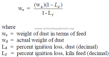
1.13 Conversion of Kiln Dust Weight to Kiln Feed Weight
Dust collected in a precipitator or bag house of a kiln shows a different loss on ignition
than the kiln feed because it has been partially calcined. For inventory control purpose and in
some kiln operating studies it is often necessary to express the weight of dust in terms of
equivalent feed weight.
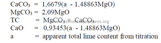
1.14 Calculation of Total Carbonates from Acid-Alkali Titration
This method is only applicable when the MgO content of the sample is known. Values
from the raw (unignited) basis are used for the calculation.
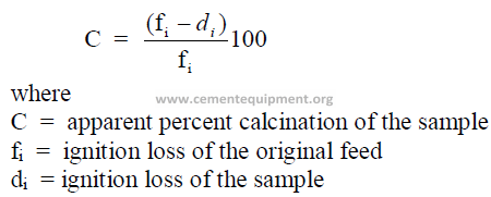
1.15 Percent Calcination
Kiln feed or dust samples taken at any location of the kiln are often investigated for
the apparent degree of calcination the sample has undergone.
PROBLEMS AND SOLUTIONS
Problems and examples shown in this chapter are all subsequent chapters are arranged
in the same sequence as the formulas are presented in the chapter.
Chapter 2
KILN FEED MIX CALCULATIONS
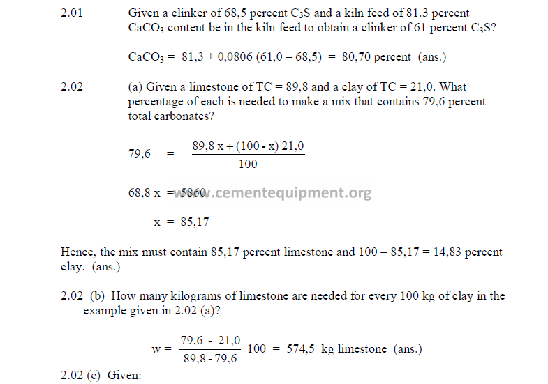
2.01 CaCO3 Required to Obtain a Given C3S in the Clinker
This formula should only be used as a quick reference in times when no other
analytical methods, other than the titration method, is available.
![]()
![]()
where
A = desired C3S in clinker
a = existing C3S in clinker
2.02 Two-Component Mix Calculations
a) To obtain a constant total carbonate content
This method can only be used when the MgCO3 content in the two components is
constant.
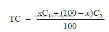
where
x = material A needed (percent by weight)
100 – x = material B needed (percent by weight)
C1 = TC in material A (percent by weight)
C2 = TC in material B (percent by weight)
TC = desired total carbonates
b) Percent of each component needed for a desired CaCO3
Use this formula only when the MgCO3 content in the two components is constant.
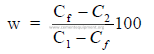
where
w = weight of material A needed for each 100 unit weights of material B
Cf = CaCO3 desired in mix
C1 = CaCO3 in material A
C2 = CaCO3 in material B
c) To obtain a constant C3S/C2S ratio
Insert the values found from the raw material analysis (on the raw basis)
d) Formulas for mix corrections
Limestone added to a cement rock to correct mix.
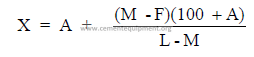
where
M = percent CaCO3 desired in mix
F = percent CaCO3 found in mix (before correction)
A = percent limestone already added
L = percent CaCO3 in limestone
X = corrected percent limestone needed to obtain M.
Clay added to a limestone to correct mix.
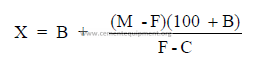
where
M = percent CaO or CaCO3 desired in mix
F = percent CaO or CaCO3 found in mix
B = percent clay already added
C = percent CaO or CaCO3 in clay
X = percent clay needed to obtain M
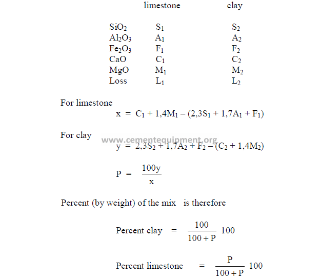
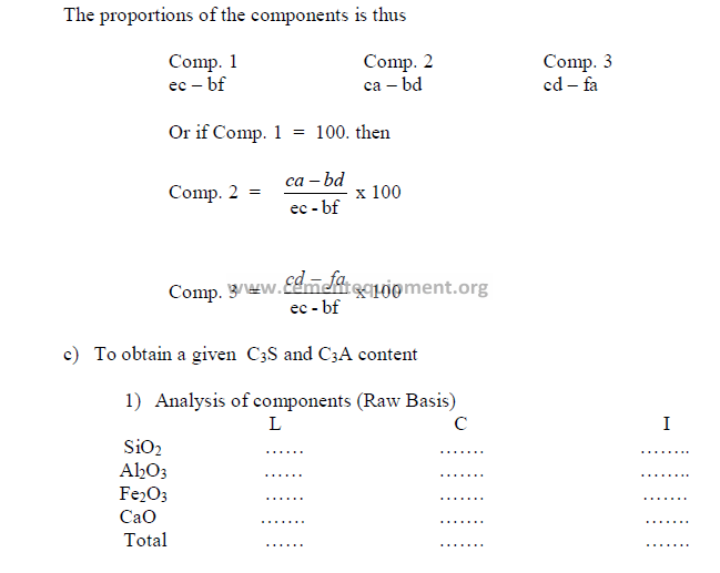
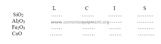
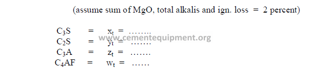
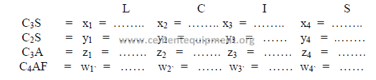
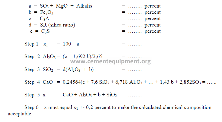
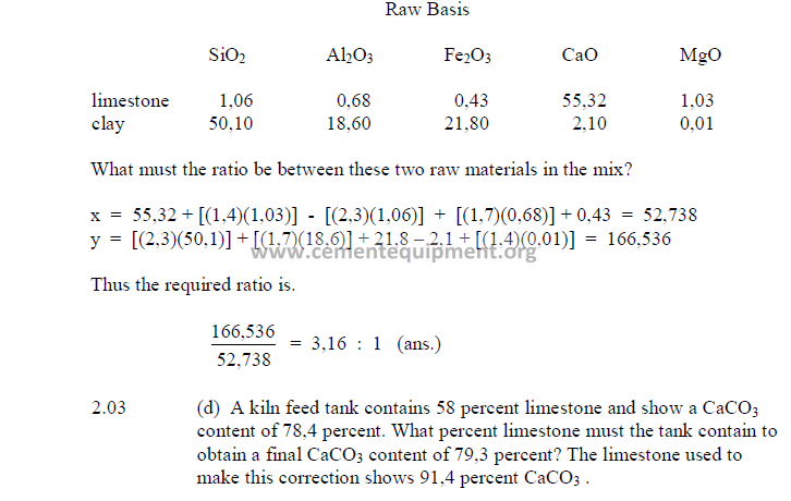
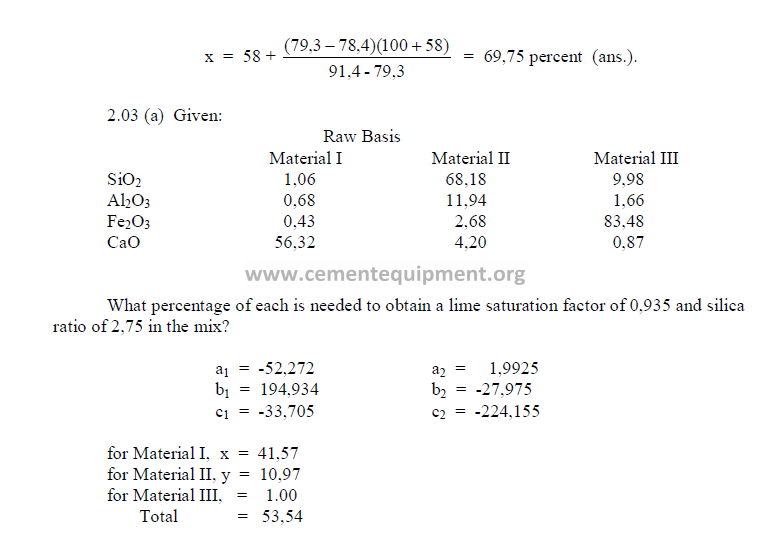
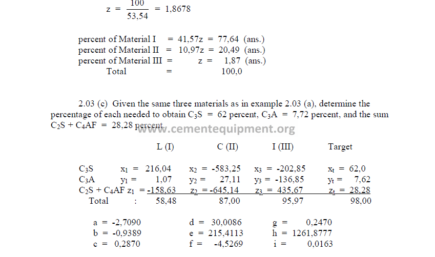
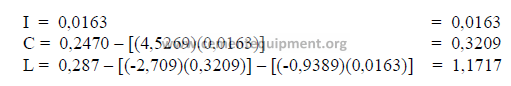
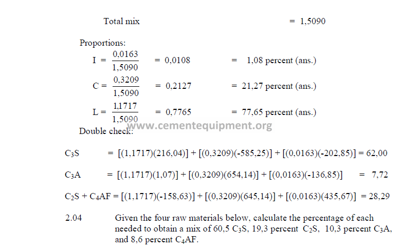
2.03 Three Component Mix Calculation
a) To obtain a desired LSF and SR
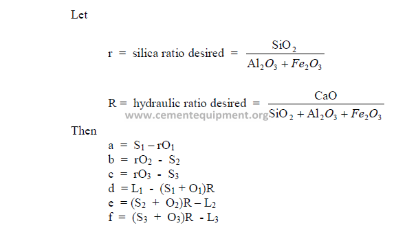
2) Desired compound composition
Whatever targets are set, make sure to make:
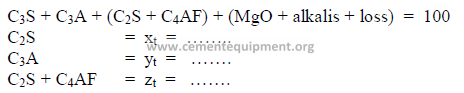
3) Theoretical compound composition for each component
To be calculated from the raw analysis data. Also make sure to use the proper sigh (+
or -).
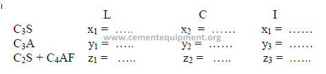
Note: Proceed with the calculations only when the sum total of the compounds
corresponds to the total of the oxides, i.e, for L: total oxides = x1 + y1 + z1 , etc.
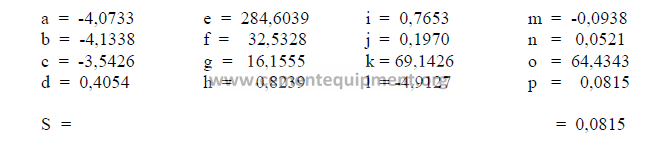
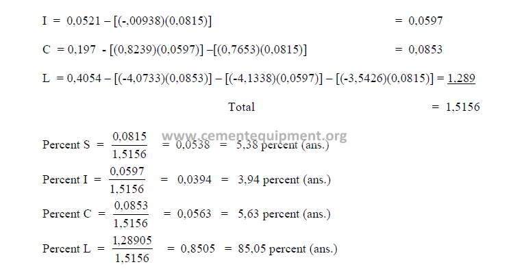
4) Calculations, auxiliary matrix
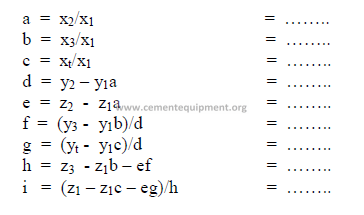
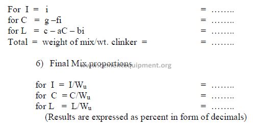
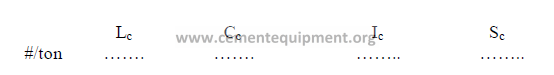
5) Weight of each component needed per unit weight of clinker
All weights units can be used, i.e., the results can be expressed in ton/ton, or kg/kg of
clinker. Results obtained must all be positive numbers. If any of the results are negative, the
desired mix cannot be obtained with the given raw materials. Fighter the targets have to be
changed or other suitable raw materials must be selected.
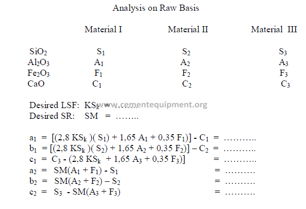
2.04 Four – Component Mix Calculation
a) Analysis of components (raw basis)
b) Desired clinker composition
c) Theoretical compound composition for each component
(to be calculated from raw analysis data, make sure to use the proper sign)
d) Raw material costs
(insert here the total costs per ton, for each raw material. These costs will
later be used to determinate the cost of the calculated mix)
Note: The sum total of the oxides of each raw material must equal the
sum total of the compounds of that material.
e) Calculation, auxiliary matrix
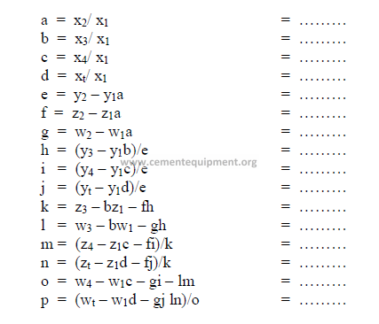
note: Make sure to indicate the proper sign in the results.
f) Weight of each component required per unit weight of clinker.
The result can be expressed in terms of kg/kg clinker. Results obtained must all be
positive numbers.
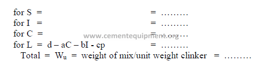
g) Final mix proportions
Note: All results are expressed in terms of a decimal.
h) Cost of the mix
The cost of the mix per unit weight of clinker can be calculated as follows:

2.05 Determination of Chemical Composition
When certain properties are required in a mix, a preliminary investigation of the
needed chemical composition can be made by the following trial and error method. This
method is only applicable when Al2O3/Fe2O3 is higher than 0,64.
Desired:
PROBLEMS AND SOLUTIONS
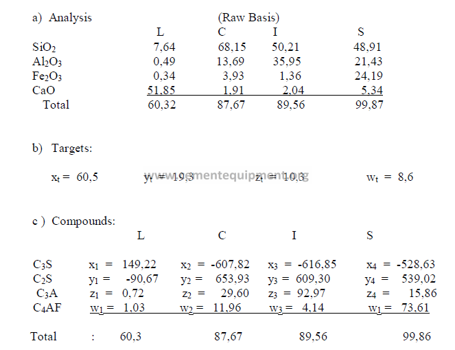
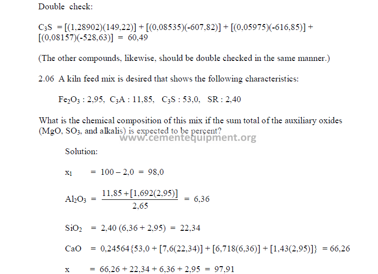
The sum total of the primary oxides is 97,91 and x1 has been found earlier to be 98,0.
Therefore, this composition is acceptable since the two agree closely with each other.
Chapter 3
KILN FEED SLURRY
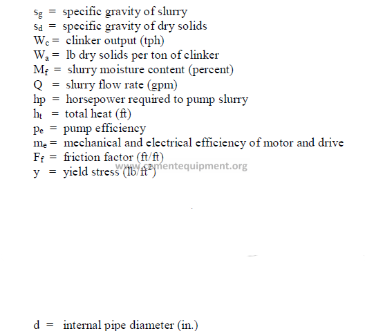
3.01 Specific Gravity and Pulp Density of Slurries
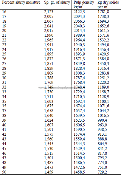
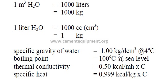
3.02 Properties of Water
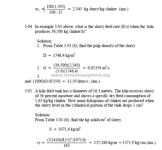
3.03 Mass of Slurry Required per Mass of Clinker
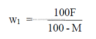
Metric units can be employed in this formula.
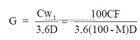
3.04 Slurry Feed Rate Required
3.05 Clinker Production for a Given Slurry Rate
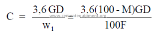
C = clinker rate (long tons per hour)
c = clinker rate (short tons per hour)
w1 = mass slurry per mass of clinker
D = pulp density of slurry (kg/m3)
F = mass dry feed per mass of clinker (tons/ton) or (kg/kg)
G = slurry rate (m3/s)
g = slurry rate (gpm)
M = percent moisture
3.06 Clinker Production per Slurry Tank Unit
Note: This formula applies only to the cylindrical portion of the slurry tank.
![]()
![]()
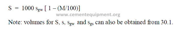
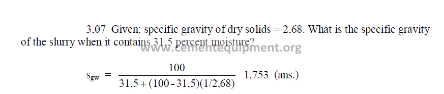
3.07 Specific Gravity of Slurry
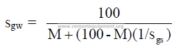
3.08 Dry Solids per unit Volume of Slurry
CT = tons clinker per meter of slurry tank height
F = mass of dry feed per mass of clinker (kg/kg) or (tons/ton)
R = radius of slurry tank (m)
S = kg solids per m3 of slurry
sgs = specific gravity of dry slurry
sgw = specific gravity of slurry
PROBLEMS AND SOLUTIONS
3.03 A given kiln uses a slurry of 32 percent moisture and the dry solids rate
has bee found to be 1,593 kg/kg clinker. What is the slurry consumption on this
kiln?
Chapter 4
CHEMICAL AND PHISICAL PROPERTIES OF
MATERIALS USED IN CEMENT MANUFACTURING
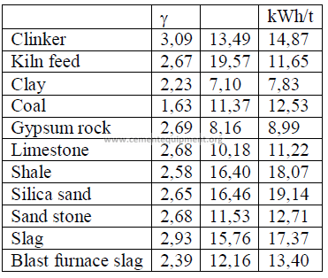
4.02 Bulk Densities of Common Materials
kg/m3
Aluminum 2595
Asbestos 3045
Brick (basic) 2400-2965
(alu.) 1520-1760
(firecly) 1360-1520
Cement (packed) 1506
(loose) 1200-1440
Clay (loose) 960-1200
Clinker 1440-1700
Coal (loose) 800-865
Coke 480-640
Concrete (reinforced) 2325
Gravel (loose) 1760
Ice 919
Iron (Cast) 7210
Iron Ore 2805
Kiln Feed (dry) 1360
Kiln Dust (loose) 1040
Limestone 1520
Mortar 1665
Fuel Oil 895
Sand 1520
Shale 2480
Slurry (@35 percent H2O) 1682
Steel 7850
Water 1000
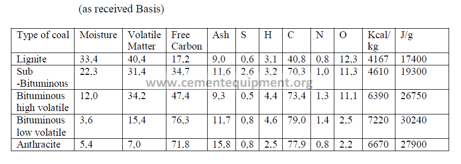
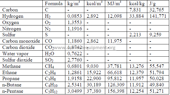
4.03 Typical Coal Analysis
4.04 Typical Fuel Oil Properties
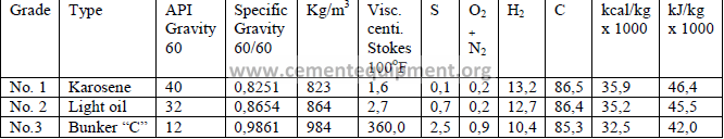
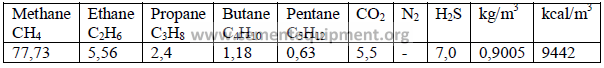
4.04 Typical Gaseous Fuel Properties
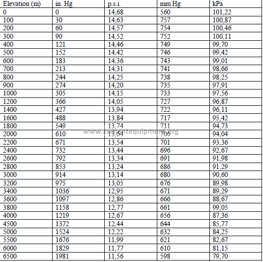
4.05 Barometric Pressure at Different Altitudes
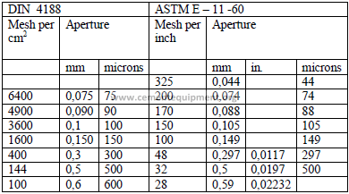
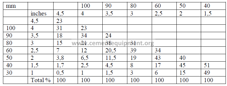
4.06 Sieve Sizes
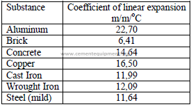
4.07 Coefficients of Linear Expansion
4.09 Properties of Air
4.10 Particulate Concentration in Gases
For gases:
1mg/liter = 24,04 m ppm
1mg/m3 = 0,02404 m ppm
where
m = molecular weight of gas
4.11 Selected International Weights
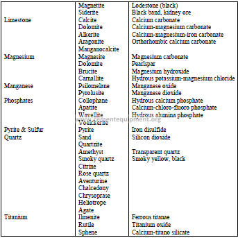
4.12 Selected Minerals and Ores
4.13 Classification of Minerals
a) Ingeous rock
These are formed by the intrusion or extrusion of magma or by volcanic activity. The
following minerals belong to this group:
Granite : Crystalline quartz and orthoclase
Orthoclase : Feldspar containing potassium
Plagioclase : Feldspar containing calcium and sodium
Quartz : Silicon dioxide
Biolite : A dark green form of mica consisting of silicate of Fe, Mg, K, or Al
Pyroxene : Silicate minerals containing calcium, sodium, magnesium, iron, or
aluminum
Olivine : Silicate of magnesium and iron
Magnetite : Oxide of iron
b) Sedimentary rock
These are formed by deposits of sedimentation. They can also consist of fragments
of rock deposited in water or by precipitation from solutions and organisms. The following
rocks belong to this group:
Gravel Shale Chalk
Sandstone Limestone Marl
Siltstone Gypsum Coral
c) Metamorphic rock
These are minerals that have been changed by the action of heat, pressure, and water.
The following minerals belong to this group:
Gneiss : Laminated or foliated metamorphic rock
Schist : Crystalline metamorphic rock with foliated structure along
parallel planes
Marble : Metamorphic crystallized limestone
Quartzite : Metamorphic sandstone
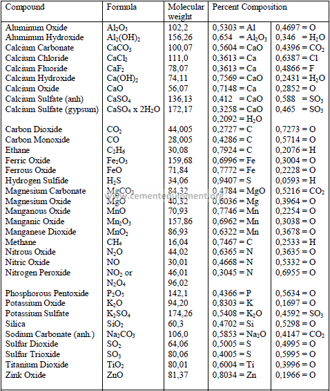
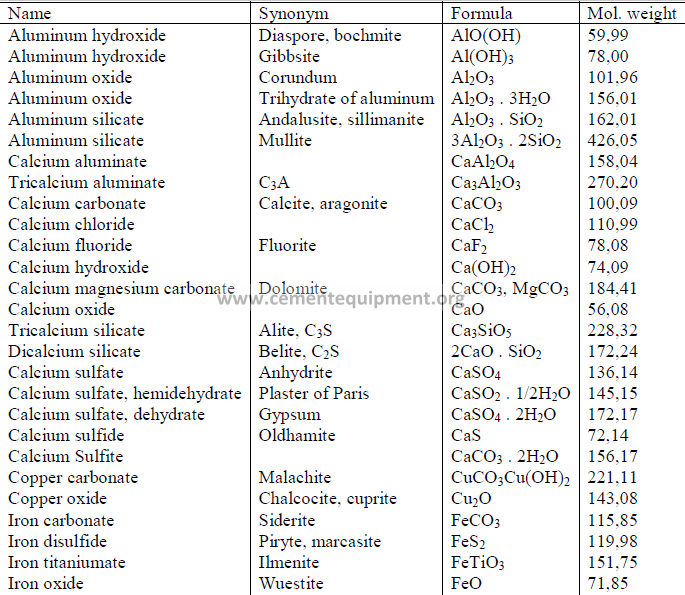
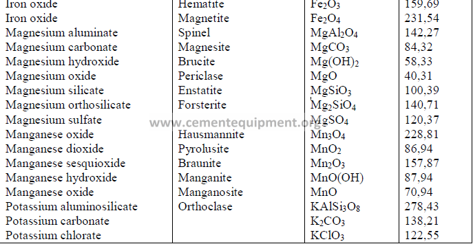
4.14 Chemical Formula and Molecular Weight of Common Minerals
Chapter 5
FORMULAS AND DATA USED IN COMBUSTION
CALCULATIONS
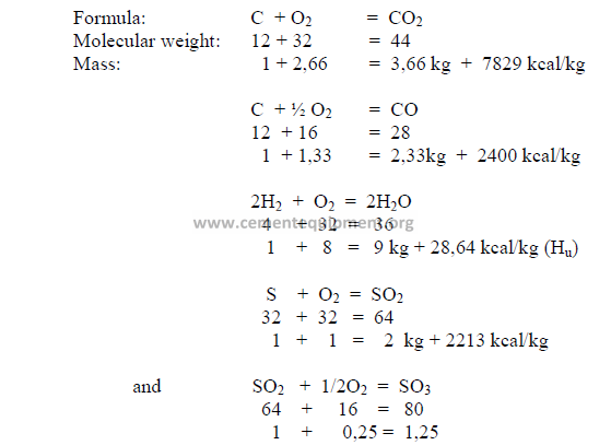
5.01 Termochemical Reactions
5.02 Combustion Constants
Note: Volumes at 16oC and 760 mm Hg.
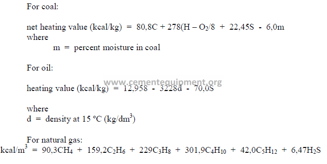
5.03 Heat Value of Fuel
The heat value of a fuel is usually determined in a calorimeter. For an approximate
indication, the heat value can also be calculated from the ultimate analysis. Values for C
(carbon), S (sulfur), H (hydrogen), etc., are expressed in terms of percent by weight for coal
and in terms of percent by volume for natural gas.
5.04 Conversion from “Gross” to “Net” Heating Value’
The net heating value accounts for the heat losses that are experienced for the
evaporation of the moisture in the fuel as well as the water that is generated by the
combustion of hydrogen. Heating values obtained in the calorimeter are “gross” values and
can be converted to the “net” basis by the following formulas:
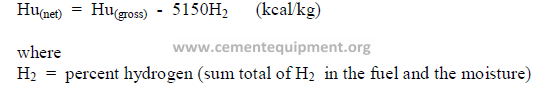
In Europe it is the custom to express the heating value or fuel consumption in terms of
the “net” basis whereas in North America the “gross” heating value is generally used.
5.05 Analysis of Coal
a) Ultimate analysis
C + H + N + S + O + Ash = 100 percent (by weight)
where
C = percent carbon, H = percent hydrogen, N = percent nitrogen,
S = percent sulfur, O = percent oxygen.
The percent oxygen (O) is not determined by analytical methods but calculated by
difference to make the sum total equal to 100.
b) Proximate analysis
V + free C + ash + m = 100 percent
where
V = percent volatiles,
free C = percent free carbon,
m = percent moisture
The percent free carbon is calculated by difference to make the sum total equal to 100.
5.06 Methods of Expressing Solid Fuel Analysis
Analysis of solid fuels should be reported with a note containing a remark in respect to
the method in which the analysis is expressed. The following are the methods (basis)
frequently used:
a) “as analyzed”
b) “dry basis”
c) “as received”
d) “combustible basis” (moisture and ash free)
e) “as fired”
For inventory control purposes it is of advantage to express coal tonnage, heating
value and its composition on the “dry basis” to eliminate the fluctuations coal undergoes
when it is stored and exposed to weathering.
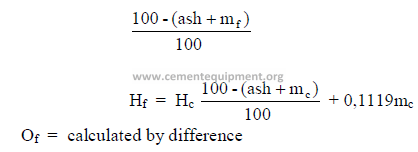
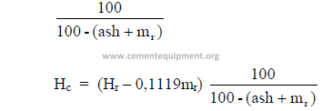
5.07 Conversion of Coal Analysis to Different Basis
Let
Y = percent C, S, N, or percent ash
O = percent oxygen
H = percent hydrogen
m = percent moisture
subscript:
a = “as analyzed” basis
d = “dry basis”
r = “as received” basis
f = “as fired” basis
c = “combustible” basis
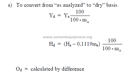
a) To convert from “as analyzed” to “dry” basis
b) To convert from “dry” to “as received” basis
Multiply all components, except hydrogen, by the factor

c) To convert from “dry” to “as fired” basis
Multiply all components, except hydrogen, by the factor
![]()
![]()
Note: in b) and c) above, the percent hydrogen is calculated as follows:
![]()
![]()
d) To convert from „as received” to „dry” basis
Multiply each component, except the hydrogen, by the factor
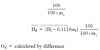
e) To convert from “combustible” to “as fired” basis
Multiply each component, except the hydrogen, by the factor
f) To convert from “as received” to “combustible” basis
Multiply each component, except the hydrogen, by the factor
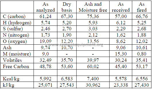
The following table shows clearly how the values of a coal analysis and the heating
value can change when the analysis is expressed in different terms.
5.08 Typical Coal Ash Analysis
For a cement chemist, it is important to know the chemical composition of the coal
ash. The majority of the ash, during the burning of coal, enters the clinker and modifies its
chemical composition. On coal fired kilns, it is not only important to maintain a uniform kiln
feed but also to fire the kiln with a coal of uniform composition. In plants, where coal
originates from several different suppliers, provisions should be made to blend these coals
before they are fired in the kiln. A typical analysis of coal ash is shown in the following:
![]()
![]()
5.09 Fuel Ignition Temperature
The approximate ignition temperature of various fuels are
ºC
Coal 250
Wood 300
Bunker C oil 200
Diesel fuel 350
Natural gas 550
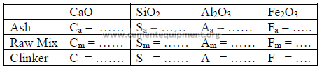
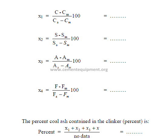
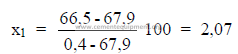
5.10 Percent Coal Ash Absorbed in Clinker
The percent coal ash contained in the clinker can be calculated from the loss-free
analysis of the ash, raw mix, and clinker as follows:
Analysis
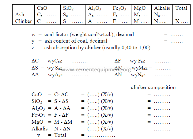
5.11 Effect of Coal ash on Clinker Composition
Changes in the composition of the clinker as a result of coal ash addition can be
calculated by the following method:
Analysis (loss-free)
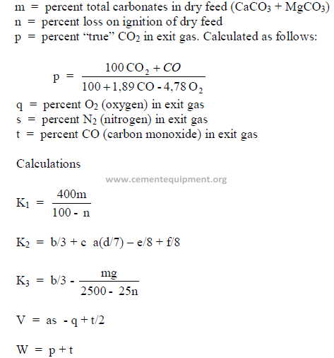
5.12 Determination of Theoretical Fuel Consumption
Knowing the properties of the coal, kiln feed, and the exit gas allows an engineer to
calculate the coal consumption by using Dr. Kuhl’s formula:
Data needed:
a = constant, 0,266
b = percent carbon in dry coal
c = percent hydrogen in dry coal
d = percent nitrogen in dry coal
e = percent oxygen in dry coal
f = percent sulfur in dry coal
g = percent ash in dry coal
What is the coal consumption on this kiln?
PROBLEMS AND SOLUTIONS
What is the net heating value of this coal expressed in terms of kcal/kg?

5.10 Given the following analysis on a loss free basis;
What percent ash does the clinker contain?
Chapter 6
pH: HYDROGEN – ION – CONCENTRATIONS
6.01 Definition of pH
The pH value of a chemical is indicated by the negative log of the hydrogen-ionconcentration
(hc +).
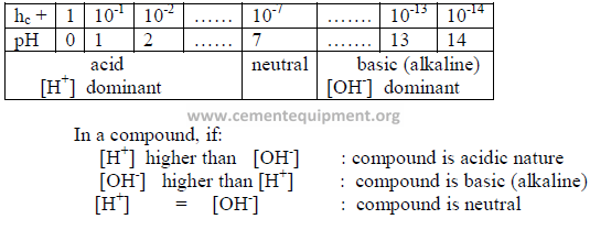
6.02 Calculation of pH
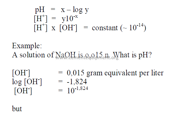
P A R T II
B U R N I NG
Chapter 7
TECHNICAL INVESTIGATION OF
KILN PERFORMANCRE
Introduction
The significant formulas for a study of the kiln performance and efficiency are given.
An engineer should follow the sequence in which the formulas are presented herein as many
calculation require the results obtained from earlier computations.
To simplify the engineers task, all the formulas are presented in the form of work
sheets that can be used to arrange the study in an orderly fashion. At the conclusion,
a summary sheet is also given to compile all the significant results of this study.
Data, formulas, and results are presented in metric system units by using the
appropriate worksheets in this chapter.
These worksheets can also be used to perform studies of parts of the kiln system
(e.g., the cooler operation). The reader should have no difficulties in selecting the appropriate
formulas from the worksheets in these instances.
For a complete study, it is essential that the kiln data be selected during a time when
the kiln operates in a stable and uniform manner.
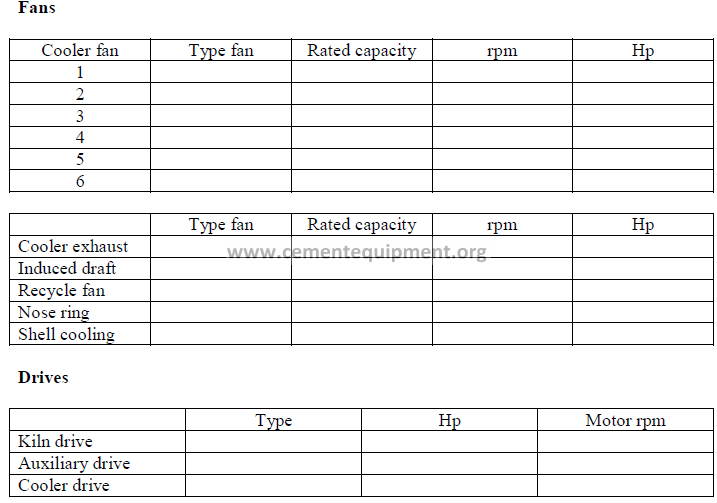
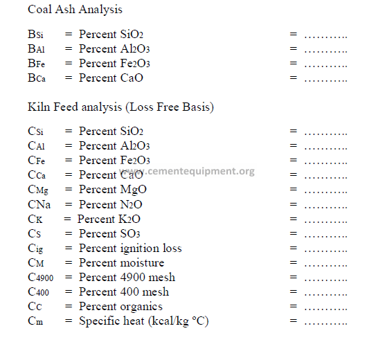
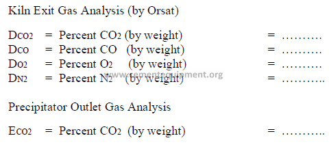
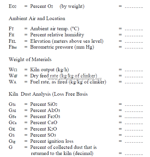
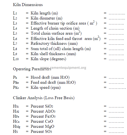
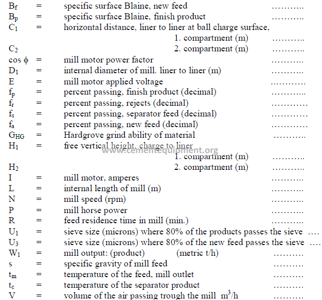
7.01 Technical Information on kiln Equipment
Plant location:____________________________________ Kiln: _____________________
Kiln
Process: ___________________________________________________________________
Manufactured by: ____________________________________________________________
Year placed in operation: ______________________________________________________
Types of clinker produced: _____________________________________________________
Types of fuel burned: _________________________________________________________
Primary air source: ___________________________________________________________
Feeder type: ________________________________________________________________
Type of dust collector: ________________________________________________________
Dust processing: _____________________________________________________________
Preheater
Type: _____________________________________________________________________
Manufactured by: ___________________________________________________________
Year: _____________________________________________________________________
Cooler
Type: ____________________________________________________________________
Manufactured by: ___________________________________________________________
Year: _____________________________________________________________________
Other kiln equipment
Function Type Hp
……….. …….. ………
……….. …….. …………
……….. …….. …………
Date of investigation:_________________________________________________________
Tested by: _________________________________________________________________
Chapter 8& 9
KILN PERFORMANCE AND EFFICIENCY
Data needed
Fuel Analysis (Oil or Coal – as Fired)
AA = Percent ash = ………..
AH = Percent hydrogen = ………..
AC = Percent carbon = ………..
AN = Percent nitrogen = ………..
AO = Percent oxygen = ………..
AS = Percent sulfur = ………..
AM = Percent moisture = ………..
AQ = Heat value (kcal/kg) = ………..
AJ = Heat value (kJ/kg) = ………..
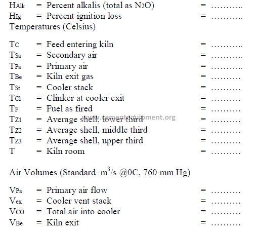
CALCULATIONS
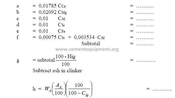
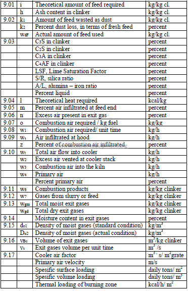
9.01 Amount of Feed Required to Produce One Kilogram of Clinker
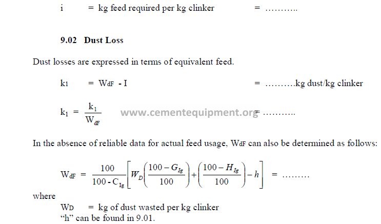
9.03 Potential Clinker Compounds and Clinker Factors
Page 102 and 103 are missed
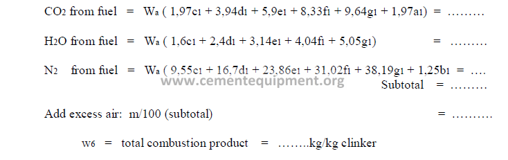
9.11 Products of Combustion
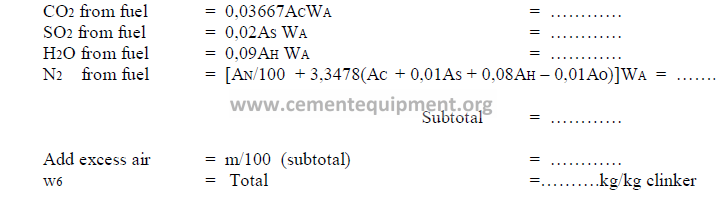
Note: For natural gas firing, use the formula 13.08 in chapter 13.
9.12 Weight of Gases from the Feed
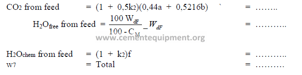
Note: The assumption is made that wasted dust has been 50% calcined. Find a, b, f in 9.01
and k2 in 9.02.
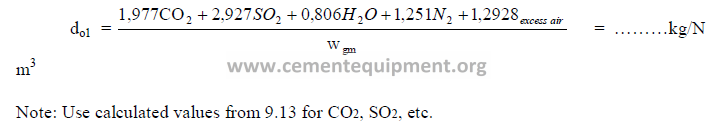
9.13 Total Weight of Kiln Exit Gases
Adding the products in 9.11 and 9.12 gives the total weight of exit gas
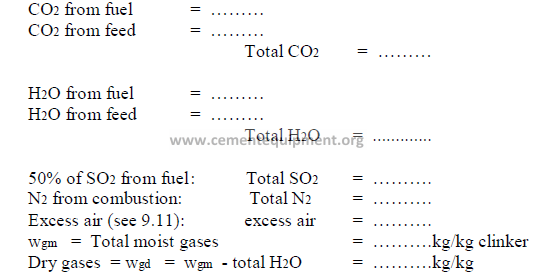
9.14 Percent Moisture in Kiln Gas
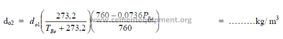
9.15 Density of Kiln Exit Gas
a) At 0 C, 760 mm Hg
b) At prevailing pressures and temperatures
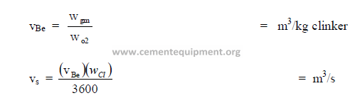
9.16 Volume of Moist Kiln Exit Gas
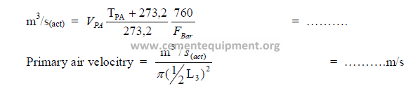
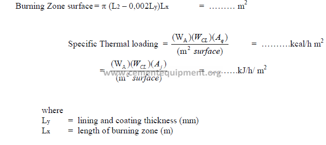
9.17 Kiln Performance Factors
a) Cooler air factor
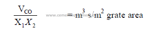
b) Primary air velocity
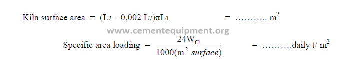
c) Specific kiln surface area loading.
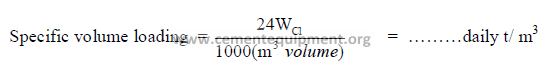
d) Specific kiln volume loading.
Using the “inside lining” kiln volume, the specific volume loading in terms of daily metric
tons production is calculated as follows:
e) Specific thermal loading of the burning zone.
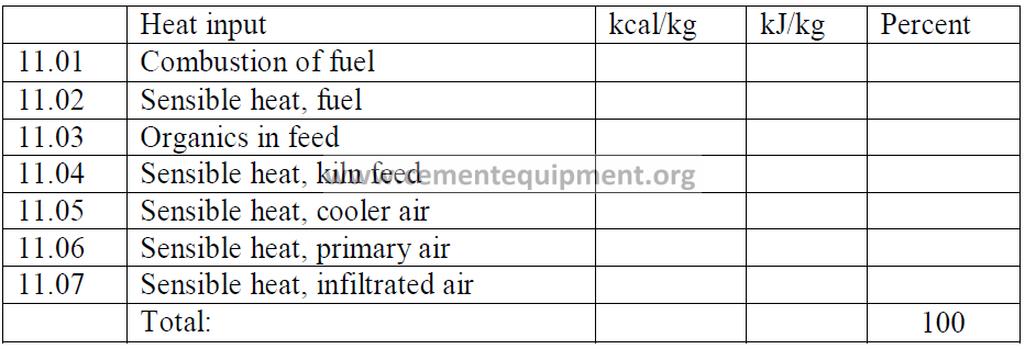
Chapter 10 & 11
HEAT BALANCE
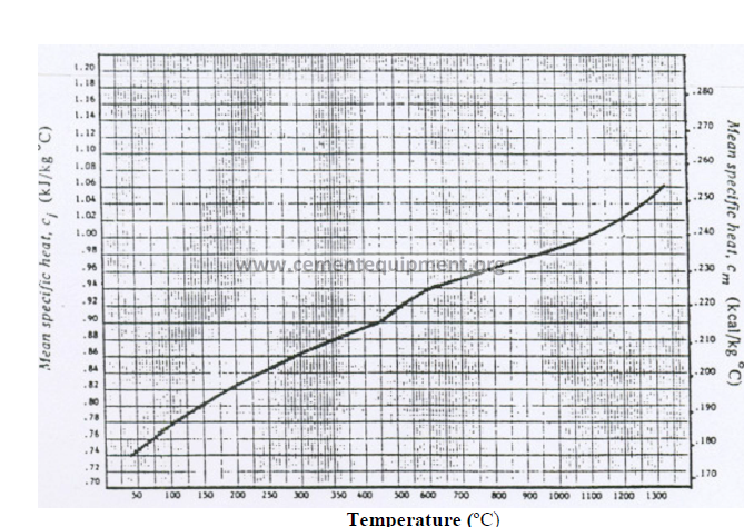
In the appendix, the reader will find graphs for the mean specific heat of gases and
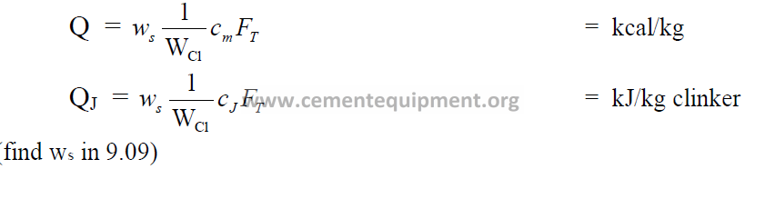
solids that will be used in the ensuing calculations. In all the formulas given, “Q” denotes the
heat content (kcal/kg), “QJ” , and “c8” the mean specific heat in terms of (kcal/kg)(C), “cJ”
in terms of (kJ/kg)©.
HEAT INPUT
11.01 Heat Input from the Combustion of Fuel
11.02 Heat Input from Sensible Heat in Fuel
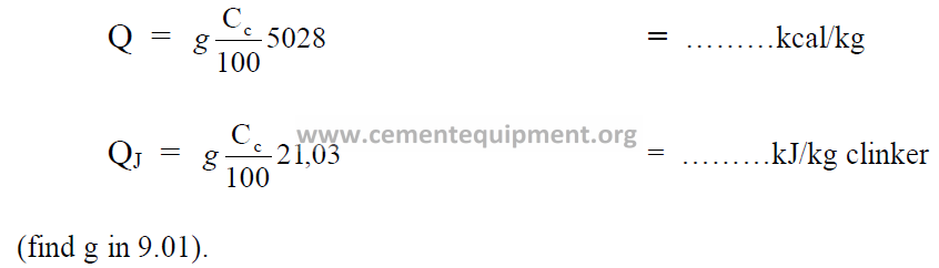
11.03 Organic Substance in Kiln Feed
It is assumed that the organic matter in the kiln feed has a constant heat value of
5028 kcal/kg and 21,036 kJ/kg.
11.04 Heat Input from Sensible Heat in Kiln Feed
11.05 Heat Input from Cooler Air Sensible Heat
11.06 Heat Input from Primary Air Sensible Heat
Include in this calculation only that amount of primary air which originates from the
atmosphere. Do not include the fraction of primary air that has its origin from the cooler.
11.07 Heat Input from Infiltrated Air Sensible Heat
When the temperature in the area where the majority of the infiltration takes place, is
significantly different from “T”, use the appropriate temperature for this calculation.
HEATS OUTPUTS
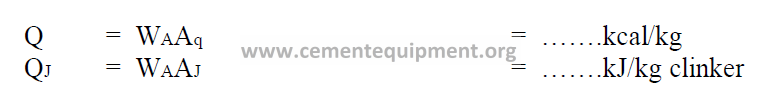
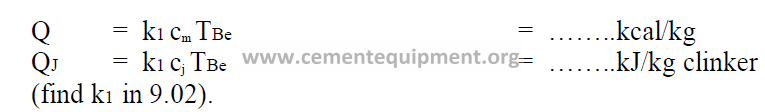
11.08 Heat Required for Clinker Formation
For “Q” in terms of kcal/kg, the result of 9.04 can be entered here directly.
Q = ………kcal/kg clinker
In the International system of units (SI) this heat fraction is calculated as follow:
![]()
![]()
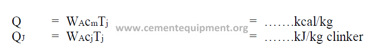
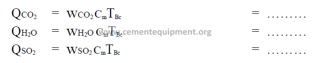
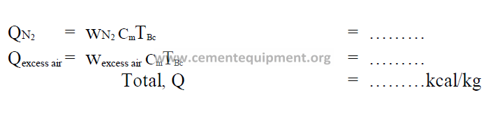
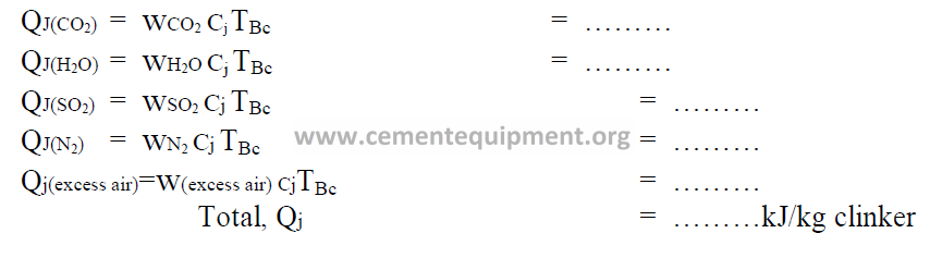
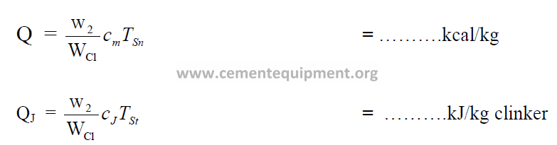
11.09 Heat Loss with Kiln Exit Gas
The heat loss in the exit gas is calculated from the heat content of each individual gas
component. The weights of these components has been calculated in 9.13.
In terms of the International system of units (SI):
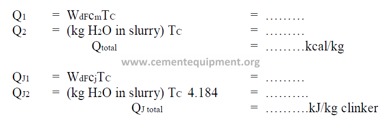
11.10 Heat Loss Due to Moisture in Feed of Slurry
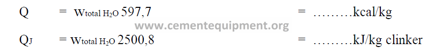
The total weight of water, (wtotal H2O) can be found in 9.13. The remits obtained represents only the amount of heat that has to be expanded to turn the given weight of water into steam at 0 ºC. The heat losses associated with raising this steam to the kiln exit gas
temperature have been included in 11.09.
11.11 Heat Loss Due to Moisture in Feed or Slurry
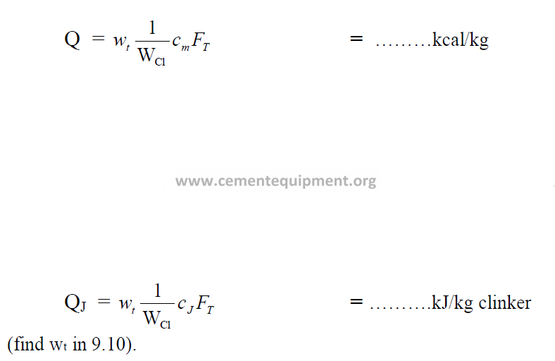
11.12 Heat Loss with Clinker at Cooler Discharge
11. 13 Heat Loss at Cooler Stack
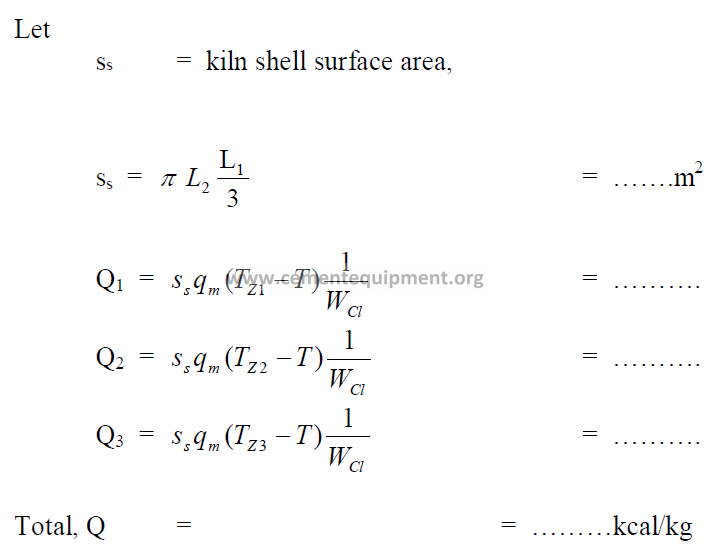
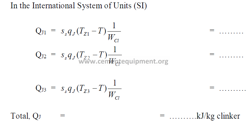
11.14 Heat Losses by Radiation on Kiln Shell
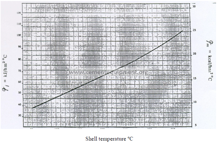
In the appendix find the heat transfer coefficient qm (kcal/ m2 h C) and qJ (kJ/ m2 h C) for
the average shell temperature, Tz, in each zone of the kiln.
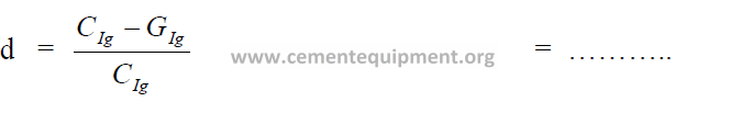
11.15 Heat Loss Due to Calcination of Wasted Kiln Dust
Calculate first the percent calcination of the kiln dust:
Second, calculate the total carbonates in the kiln dust:
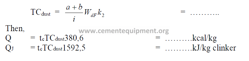
Note: Include this heat loss in the heat balance only for that fraction of the dust that is
wasted and not returned to the kiln
(find a, b in 9.01 and k2 in 9.02).
Heat Balance
Note: Unaccounted losses are calculated by difference
Chapter 12
TECHNICAL INVESTIGATION OF
THREE KILN MODELS
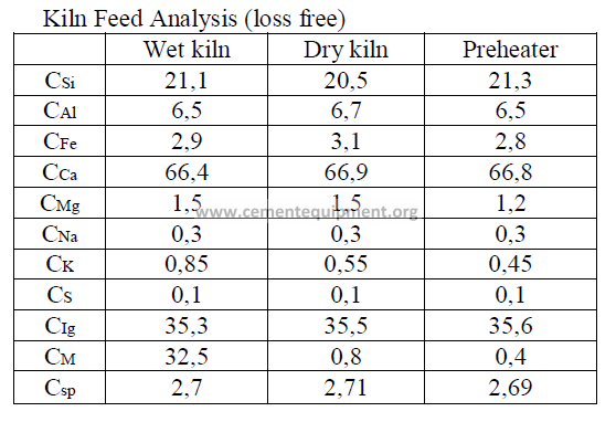
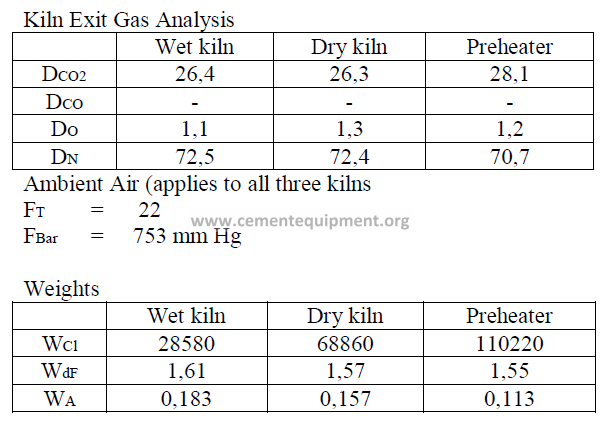
Introduction
Models of wet process, a dry process, and a suspension preheater kiln are given here
and their performance characteristics have bee calculated in accordance to formulas given
in this chapter. The data are selected values of kiln parameters typical to these types of kilns
when they are operated efficiently and properly maintained.
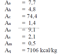
Data
Fuel analysis
(applied to all three kilns and stated on a “as fired” basis)
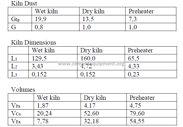
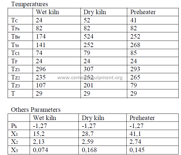
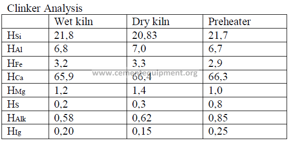
Summary of Kiln Performance Study Results
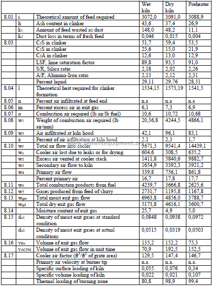
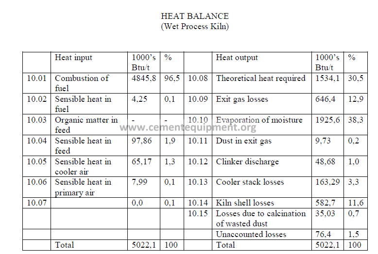
Note: Unaccounted losses are calculated by difference to make the two sides equal.
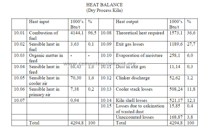
Note: Unaccounted losses are calculated by difference to make the two sides equal.
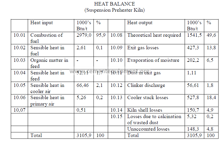
Note: Unaccounted losses are calculated by difference to make the two sides equal.
Chapter 13
COEFFICIENT, AND
COMPUTATION FOR NATURAL GAS FIRING
Compiled in this chapter, are the important parameters an engineer needs to complete
a kiln investigation as outlined in Chapters 8 through 11.
Here the engineer will find the graphs that show him at a glance the appropriate
specific heat and heat transfer coefficient to be used for his computations. The reader
is advised to make use of the appropriate graphs and formulas in accordance with the
particular system of units employed for his study.
The formulas shown in Chapter 8 through 9 apply to kilns fired with coal or fuel oil.
In this chapter, the appropriate formulas for gas firing which should be used in Chapter 8
and 9 are also shown.
13.01 Mean Specific Heat of Clinker (Base: 0 ºC)
13.02 Mean Specific Heat of Raw Materials (Base: 0 ºC)
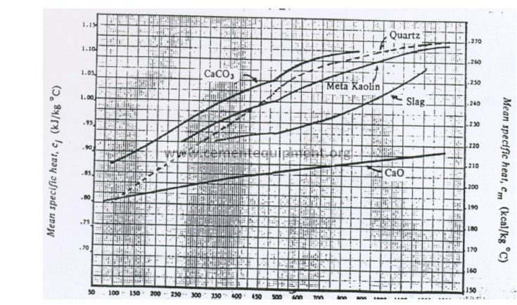
Temperature (ºC)
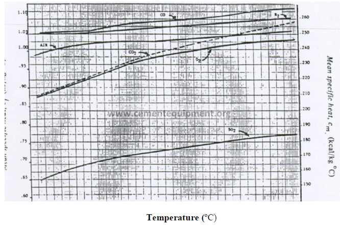
13.03 Mean Specific Heat of Exit Gas Components (Base: 0 ºC)
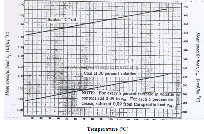
13.04 Mean Specific Heat of Fuels (Base: 0 ºC)
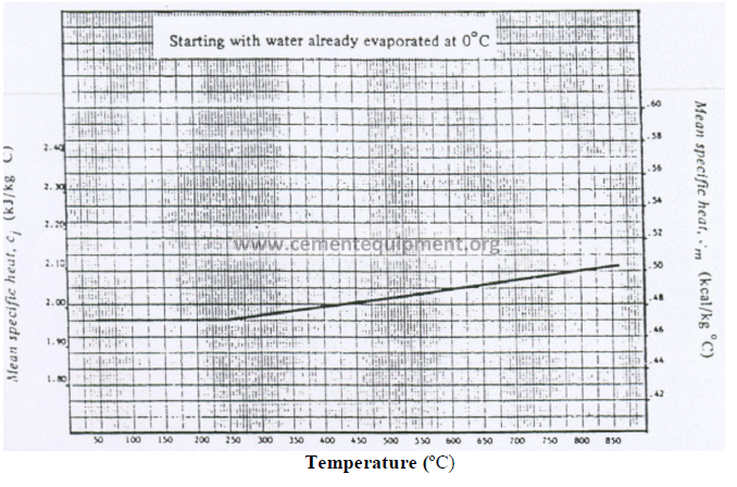
13.05 Mean Specific Heat of Water Vapor (Base: 0 ºC)
13.06 Heat Transfer Coefficients for Heat Loss on Kiln Shell
13.13 Computations for Natural Gas Firing
Analysis of natural gas fuels are usually expressed in terms of percent by volume with
is the same as molar proportions. The formulas given below allow for combustion
calculations in terms of the unit production of clinker. Hence, the results obtained are
expressed in the same terms as the results computed in this study for liquid and solid fuels.
Data required:
Combustion air required (items 9.07 and 9.07 for natural gas firing)
Weight of combustion air entering kiln (items 8.08 and 9.08 for natural gas firing)
![]()
![]()
Products of combustion (items 8.11 and 9.11 for natural gas firing).
Chapter 14
USEFUL FORMULAS IN
KILN DESIGN AND OPERATION
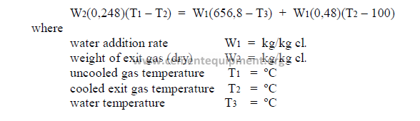
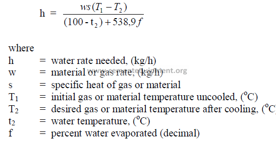
14.1 Cooling of Kiln Exit Gases by Water
Any moisture introduced into the gas stream is ultimately transferred into superheated
steam and, in doing so, absorbs heat and cools the exit gases. The equations can be solved
for any one of the unknowns if the other variables are known.
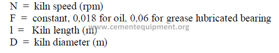
14.02 Kiln Feed Residence Time
The approximate time taken by the feed to travel the length of the kiln can be
calculated by the following formulas:
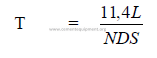
where
T = travel time (min)
L = length of kiln (m)
N = kiln speed (RPM)
D = kiln diameter (m)
S = slope of kiln (m/m)
14.03 Kiln Slope Conversion
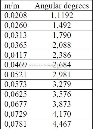
Slope is often expressed also as a percent of the kiln length
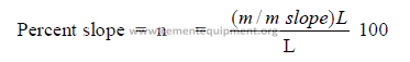
L = kiln length (m)
14.04 Kiln Sulfur Balance
If a kiln performance study has been completed in Chapter 8 and 9, the necessary data
below can be obtained from the data sheet given in these chapters.
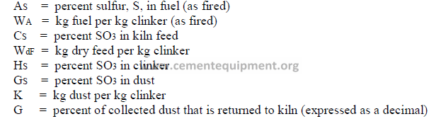
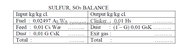
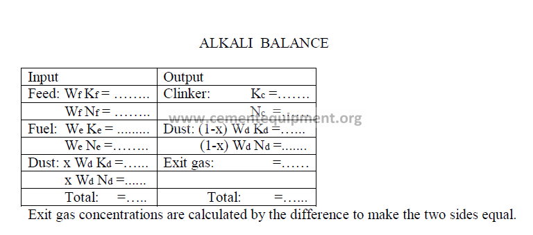
Note : Exit gas concentrations are calculated by difference to make the two sides equal
in the total.
14.05 The Standard Coal Factor, Combustion Air Requirements
To determine the approximate combustion air needed to burn a given unit weight
of coal, the formulas given below can be used when no ultimate coal analysis is available.
The combustion air requirements include here 5% excess air.
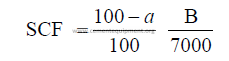
kg air/kg coal = 10,478 SCF
SCF = standard coal factor
a = percent moisture in coal (as fired)
B = heat value of coal (kcal/kg as fired
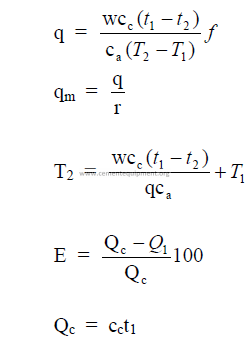
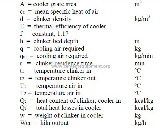
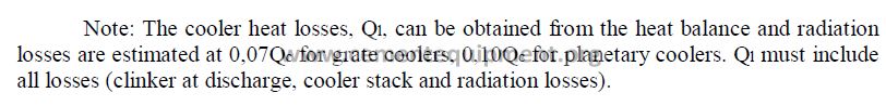
14.6 Cooler Performance
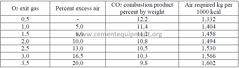
14.07 Combustion Air Required for Natural Gas Firing
In the absence of a complete analysis of the gas, the air requirements can be estimated from
the following table. This table is based on natural gas with a heating value of 9345 kcal/m3
14.8 Products of Combustion on Natural Gas Firing
One standard cubic meter of natural gas, when burned, yields the following
combustion products:
CO2 = 2,0778 kg
H2O = 1,6340 kg
N2 = 11,1003 kg
O2 = 0,3669 kg
Total = 15,179 kg
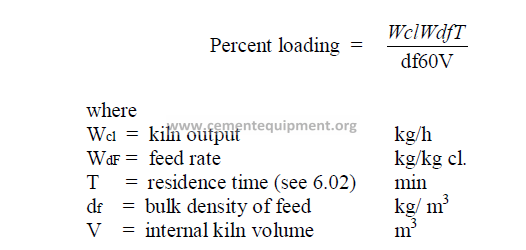
14.9 Percent Loading of the Kiln
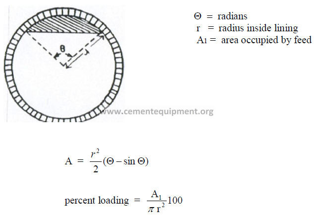
14.10 Cross – Sectional Loading of the Kiln
The formulas given here are applicable in the metric system of units
14.11 Flame Propagation Speed
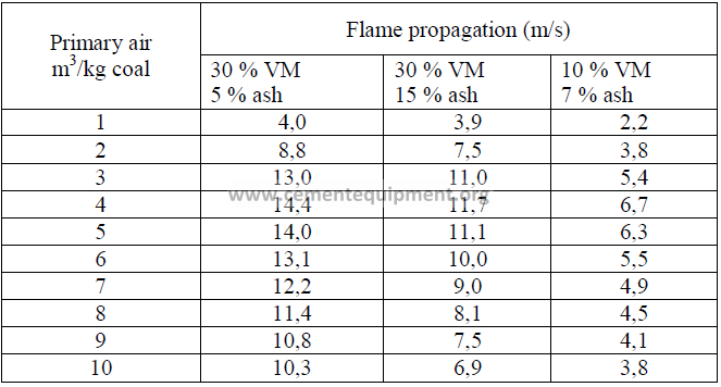
For coal fired kilns, the primary air velocity should be at least twice as high as the
flame propagation speed to prevent flash backs of the flame. Flame propagation is usually
considerably lower than the velocity needed to convey coal dust by means of primary air into
the kiln. Therefore, the minimum velocity necessary to convey coal without settling in ducts
takes precedence over flame propagation speed when setting air flow rates or designing new
burners (minimum velocity needed in ducts to prevent settling: 35 m/s). Coal burners are
usually designed to deliver a tip velocity of 45 to 70 m/s.
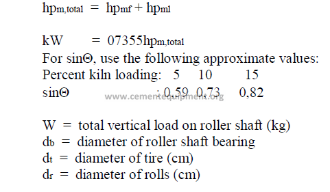
14.12 Kiln Drive Horsepower
a) Friction horsepower
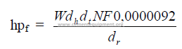
b) Load horsepower
![]()
![]()
Total kiln drive horsepower
14.13 Theoretical Exit Gas Composition, by Volume
In chapter 9, Section 9.13, the total weight of the exit gas components were
calculated. In many studies, it is desirable to express this composition in terms of percent
by volume. The following steps are taken to accomplish this.
Step 1: Convert weights of each component into kg – moles as follows:
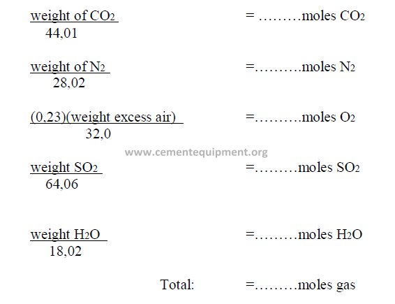
Step 2: To obtain the percent by volume of any component, divide the moles of the
component by the total moles of gas.
14.14 Conversion of Specific Heat Consumption into Annualized Costs
For U.S. currency:
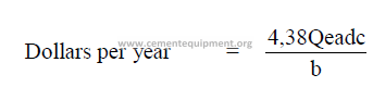
For any other currency denomination:
a = fuel costs (dollars/ton)
b = fuel heat value (Btu/lb)
c = kiln output (tph)
d = percent operating time (decimal)
A = cost per kg fuel
85
B = fuel heat value (kcal/kg)
C = kiln output (kg/h)
Qe = specific heat consumption (Btu/t)
Qm = specific heat consumption (kcal/kg cl.)
14.15 Theoretical Flame Temperature
(This formula applies only to oil or coal fired kilns)
Note: “V” can be obtained by dividing the result of 8.11, or 9.11 i.e., w6 by 1,3569WA when
metric units are using.
14.16 The “True” CO2 Content in the Exit Gases
The true CO2 content is the amount of carbon dioxide contained in the exit gases after
a correction has been made to account for the effects of excess and deficiency of air present.
14.17 Alkali Balance
Data needed:
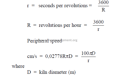
14.18 Kiln Speed Conversions
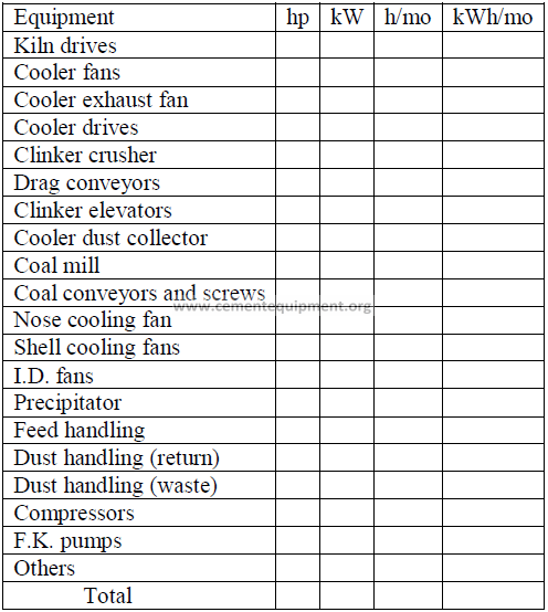
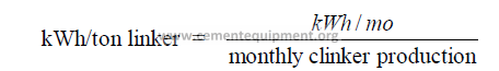
14.19 Power Audit on Kiln Equipment
kWh/ton clinker: ………………………………
kW = 0,7457 hp
h/mo = Total hours per month unit in operation
kWh/mo = (h/mo)(kW)
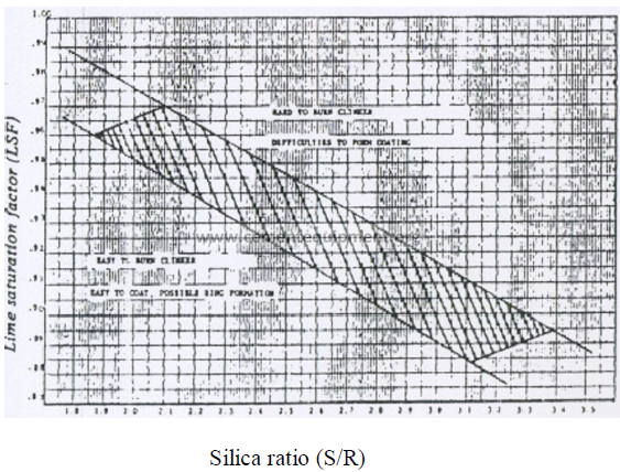
14.20 Coating and Ring Formation
The graph shown here can serve as a guideline to indicate it a given clinker
composition has the tendency to form heavy coating and rings or if coating formation would
be difficult. Clinkers that fall outside the shaded areas in their relationship between the silica
ratio and the lime saturation factor tend to be either difficult or easy coating in nature
depending on which side of the shaded area they are located. Clinker compositions that are
located within the shaded area of this graph are considered acceptable from a coating
formation viewpoint.
14.21 Relationship Silica Ratio vs. Saturation Factor
PROBLEMS AND SOLUTIONS
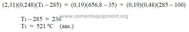
14.01 The exit gas temperature on a kiln is 285 ºC when a water spray rate of 0,19 kg
water/kg clinker is used. Exit gas rate, dry, is 2,31 kg gas/clinker and the water temperature is
35 ºC. What is the exit gas temperature of the uncooled gases?
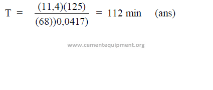
14.02 A kiln has the following characteristics:
length: 125m, diameter: 4,5m, kiln speed: 68 rph, slope: 0,0417 m/m.
What is the theoretical residence time of the feed in this kiln?
Chapter 15
CHAIN SYSTEMS IN WET PROCESS KILNS
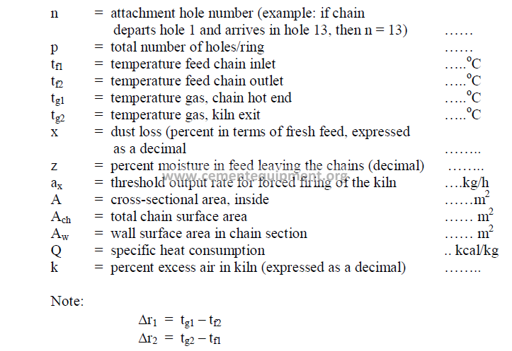
Data:
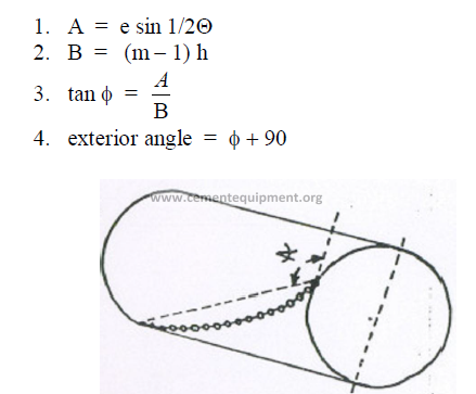
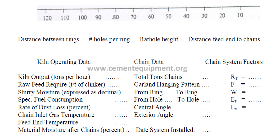
15.01 Chain Angle of Garland Hung Chains
There are three different methods commonly used to express the chain angle. To avoid
confusion, we propose new terms for each in order to make a distinction between them.
a) The central angle
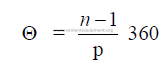
b) Exterior chain angle
Definition: The exterior angle formed between the straight line (connecting the two
attachment holes of the chain) and the perpendicular to the kiln axis. This angle, is calculated
by using the result of (a) and proceeding in the following manner:
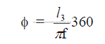
c) The chain length angle
The chain length expressed in degrees of the kiln circumstance.
15.02 Evaporation Rate (Wet Kiln)
A distinction must be made here between the total moisture given to the kiln and the
evaporation done in the chain system.
a) Total evaporation in kiln
b) Evaporation in chain system
c) Percent of evaporation done in chain system
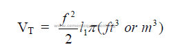
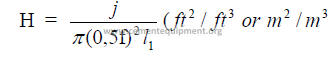
15.03 Total Heat Transfer Surface
15.04 Effective Heat Transfer Volume for Evaporation
15.05 Chain Zone to Kiln Length Ratio
15.06 Length of Chain System
a) For garland hung system
![]()
![]()
b) For curtain hung systems
![]()
![]()
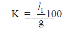
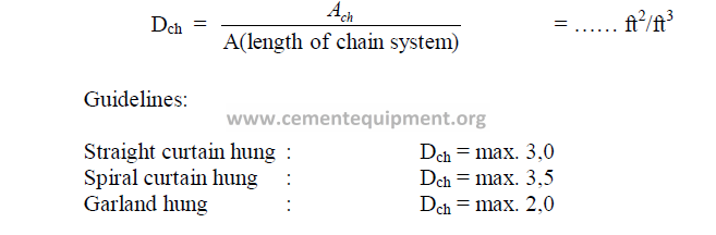
15.07 Chain Density
15.08 Heat Transfer Required in Chain System
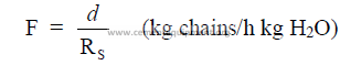
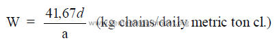
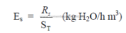
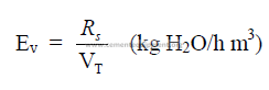
15.09 Specific Chain System Performance Factors
a) Mass of chains per mass of water to be evaporated
b) Mass of chains per daily mass of clinker production
c) Specific evaporation per unit surface area
d) Specific evaporation per unit kiln volume
e) Specific heat transfer required per unit chain surface
15.10 Chain System Design for Wet Process Kilns
A chain system design method is herein proposed that takes into account the amount
of thermal work expressed and the amount of heat made available in the system.
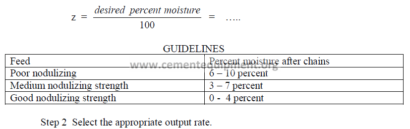
Step 1 Select the moisture in the feed leaving the chains.
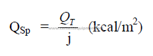
This formula was developed by the author to show the theoretical threshold output rate
for “forced firing” of the kiln. Forced firing is defined as that output rate at which excessive
dust losses occur in the kiln as a result of the gas velocity exceeding 30 ft/s downstream of the
chain system. Please note that only English systems of units are employed in this and all
successive steps. For example, use only MBtu/short ton of clinker for “Q” in the above
formula.
Step 3 Select the desired kiln exit gas temperature
![]()
![]()
For optimum fuel efficiency, it is desirable to set this temperature as low as possible
without causing condensation in the precipitator. If the temperature, at which condensation
takes place, is known, the target should be set 50oF higher. For example, when it is known
that condensation occurs at a kiln exit gas temperature of 350oF the target for tg2 should be set
at 450oF.
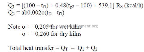
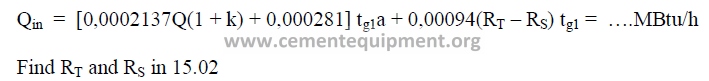
Step 4 Quantity of heat entering the chain system.
This empirical formula was developed by the author to obtain an approximate value
for the heat entering the chain system.
Step 5 Quantity of heat leaving the chain system
This formula was developed by the author to give an approximate value for the heat
leaving the kiln at the feed end.
![]()
![]()
Step 6 Heat supplied for thermal work in the chain system
![]()
![]()
Step 7 Ratio: heat supplied to heat transfer expected.
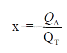
Find QT in 15.08.
The value for “x” must be close to unity, i.e., 0,90 – 1,10. When this value is outside
of this range, return to step 1 and adjust any of the variables such as z, a, c, e, tg2, or b to bring
this value in line with the above given range.
Any adjustment in the variables causes the specific heat consumption of the kiln to
change. To select the appropriate value for Q, the following guidelines can be used:
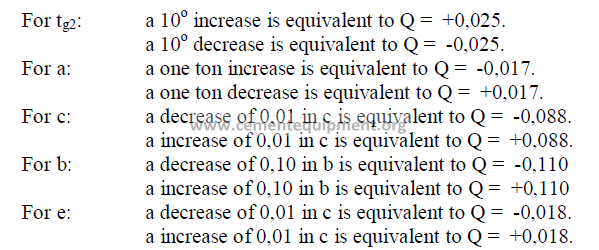
(If several of these factors are changed, the sum total changes in Q applies.)
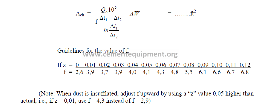
Step 8 Chain surface area required.
Formula based on the logarithmic mean temperature differential in the chain system.
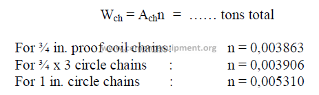
Step 9 Chain weight total
Step 10 Chain Density
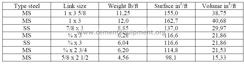
15.11 Kiln Chain Data-Round Links
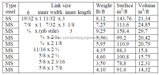
15.12 Kiln Chain Data-Proof Coil (Oval Links)
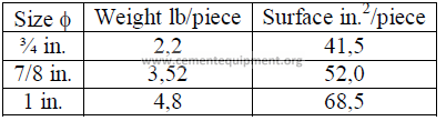
15.13 Chain Shackle Data
15.13 Chain System Record Form
Chapter 16
KILN REFRACTORY
On the North American continent, rotary kiln blocks, arches, and wedges are the most
common refractory shapes used to line rotary kilns. In countries using the metric system
of units, VDZ and ISO shapes are used. The following data will familiarize the reader with
the dimensional differences between these shapes. It is important to note that dimension “a”,
i.e., the back cord, is the face of the refractory that is in contact with the kiln shell. All shapes
are installed so that the given dimension “l” forms a parallel line to the kiln axis. Dimension
“h” indicates the lining thickness.
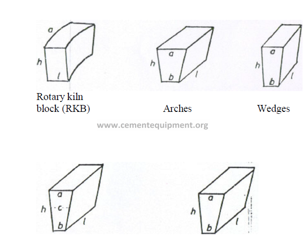
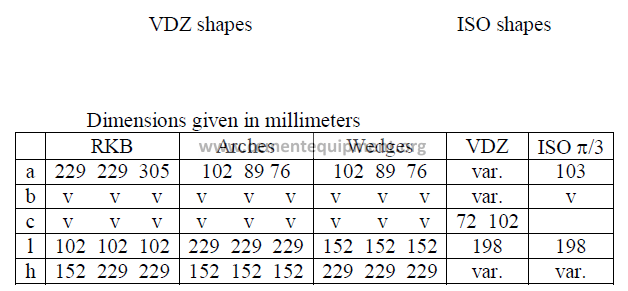
Note: VDZ and ISO shapes are usually manufactured for 160, 180, 200, 225, and
250 mm thick linings (h).
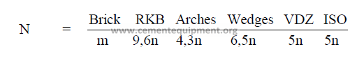
16.2 Number of Bricks Required per Ring
Outside the United States, it is customary to use two different shapes of bricks with
different backcords (a) to complete a full circle of the kiln circumference. Experience has
shown that this produces a superior fit of the refractory to the shell particularly when the kiln
shell is slightly out of round.
a) for RKB, arches and wedges
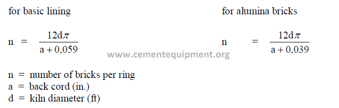
b) for VDZ shapes
The attached tables, supplied by Refratechnic GmbH, show the number of bricks each
required when a given kiln diameter is encircled with two different sizes of bricks. All of the
brick shapes shown have a uniform dimension “l” of 198 mm.
c) for ISO shapes (p/3)
ISO shapes have a uniform back cord of 103 mm. With an expansion insert of 1 mm,
the cord length becomes 104 mm which is equivalent to p/3, explaining the reason
for identifying these shapes by this nomenclature. With p a constant in the brick back cord
and the circumference of the kiln shell, the calculation for the number of bricks required
per circle becomes simple:
n = 1000 D (0,0333) = 33,33 D
where D: internal kiln shell diameter (m)
Example: How many bricks are required in ISO shapes to complete a circle on a 4,8 m
diameter kiln?
Answer: (33,33)(4,8) = 160 pieces.
16.03 Number of Bricks Required per Unit Kiln Length
a) when dimension “l” is expressed in millimeters and kiln length in meters:
P A R T III
G R I N D I N G
Chapter 17
TECHNICAL INVESTIGATION OF GRINDING MILL
Formulas for study of the grinding mill and circuit are given. To simplify the
engineers task, all the formulas are presented in the form of work sheets that can be used in
the course of the mill investigation. At the conclusion, a summary sheet is also given to
compile all the significant results of this study.
17.1 Technical Data of Grinding Circuit
Plant location: ……………………………………………. Mill: ………………………….
Type of mill: ……………………………………………………………………………………
Manufactured by: …………………………………………. Build: ………………………..
Types of products ground: …………………………………………………………………….
…………………………………………………………………….
…………………………………………………………………….
Type of grinding circuit: ……………………………………………………………………….
Separator
Type: ……………………………………………………… Size: …………………………..
Motor: ………………………………………………………………………………………….
Mill drive
Type: ………………………………………………………………………………………….
Motor: …………………………………………………………………………………………
Chapter 18 and 19
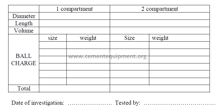
GRINDING MILL INVESTIGATION
Data needed
CALCULATIONS
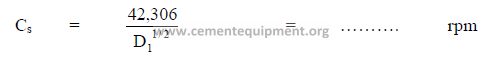
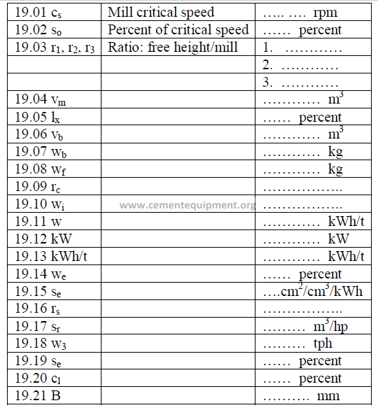
19.01 Mill Critical Speed Cs
19.02 Percent of Critical Speed
19.03 Ratio: Free Height to Mill Diameter
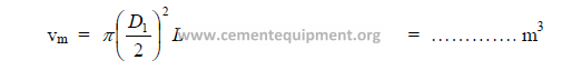
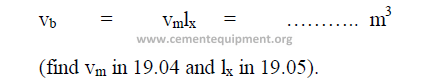
19.04 Internal Volume of Mill
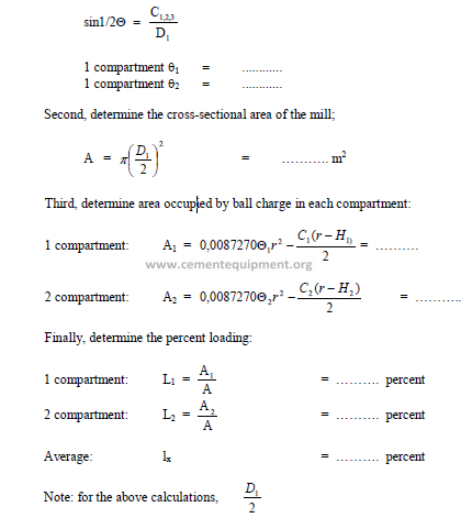
19.05 Percent Loading of Mill
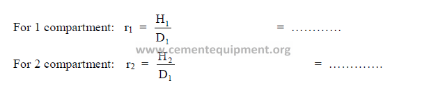
First, determine the central angle (q) for each compartment by using the formula:
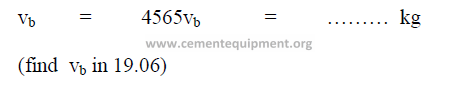
19.06 Bulk Volume of Ball Charge
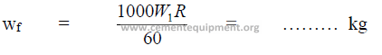
19.07 Weight of the Ball Charge
In this chapter data on the mills ball charge is given. Since this data refers usually to
the initial load of the mill, the following formula can be used to calculate the weight of the
charge based on the bulk volume occupied
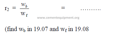
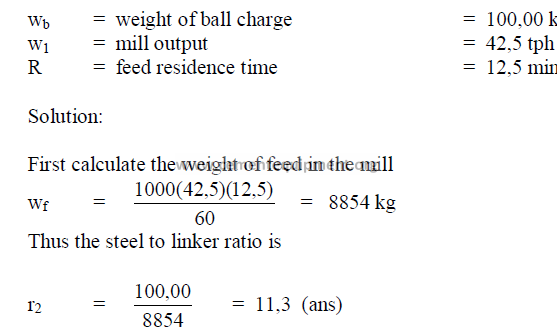
19.08 Steel of Feed in Mill
19.09 Steel to Clinker Ratio
19.10 Bond’s Laboratory Work Index
Definition: The work (kWh/t) required to reduce one metric ton of a material from
theoretical infinite size to 80% passing 100 microns.
The result applies to wet grinding in closed circuit.
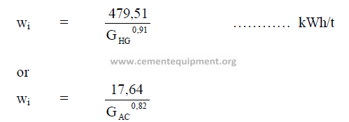
For dry grinding in closed circuit, multiply wi by 1,3333. For open circuit grinding,
dry or wet, multiply wi by 1,2. When no Hardgrove grind ability ratings are available for a
given material to be ground, use the Work Index guide lines given in Chapter 20, Section
20.01.
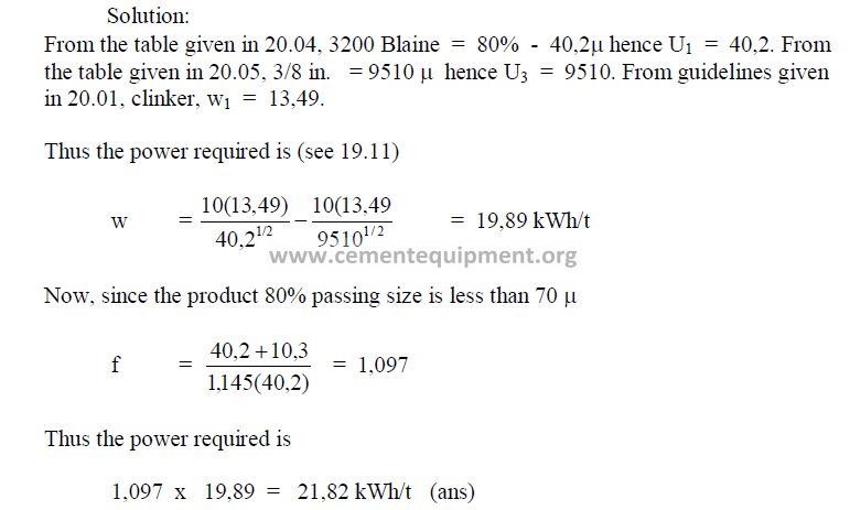
19.11 Power Required
To grind a material from any feed size to any product size, the power required for
grinding can be calculated from the equation given for Bond’s Third Theory of Comminution.
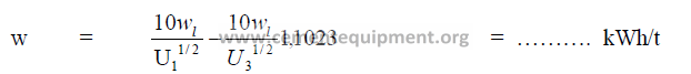
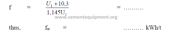
When the product 80% passing size is less than 70 microns, the result (w) above must
be multiplied by the factor “f”.
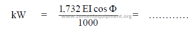
19.12 Mill Power
The kilowatts expanded in grinding, with an AC – 3 phase system is
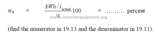
19.13 True Specific Power Demand of Grinding Mill

19.14 Mill Operating Efficiency
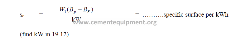
19.15 Specific Surface Grinding Efficiency
19.16 Mill Size Ratio
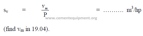
19.17 Specific Mill Volume per Horsepower
19.18 Separator Load
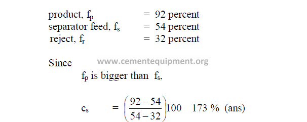
19.19 Separator Efficiency
19.20 Circulating Load
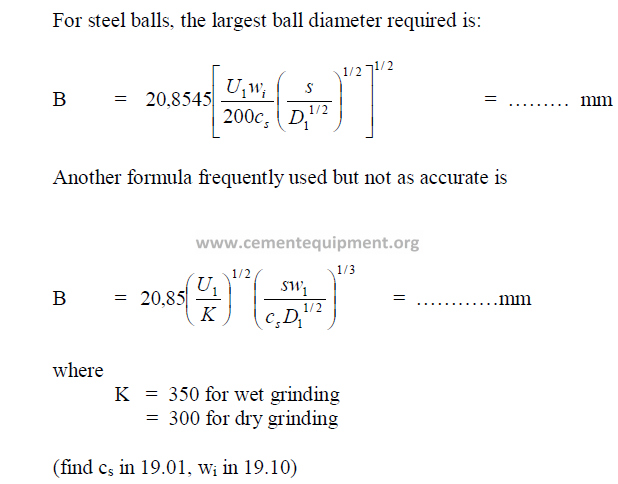
19.21 Size of Grinding Balls Required
RESULTS OF GRINDING MILL STUDY
PROBLEMS AND SOLUTIONS
19.09 What is the steel to clinker ratio of the following mill?
19.11 linker of 80 percent passing 3/8 in. has to be ground to a specific surface Blaine
of 3200 cm2/g. what is the power required (kWh/t) to do this grinding work?
19.20 What is the circulating load when a given mill shows the following fineness
passing the 325 sieve:
19.21 What is the largest ball diameter required (mm) for a mill whose critical speed
is 21.15 rpm when clinker has to be ground to 80% passing 40 m sieve. The mill
diameter is 4.0 m and the specific gravity of clinker equals 3,15.
CHAPTER 20
USEFUL DATA FOR GRINDING MILL STUDY
20.01 Work Index for Various Materials
20.02 Size Distribution for a New Ball Charge in Mill
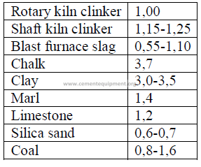
20.03 Grind ability Factor
Mill output when other materials than clinker are ground in the same mill:
20.04 Approximate 80 Percent Passing Size in Microns
The approximate value can be calculated from the specific surface Blain as follow:
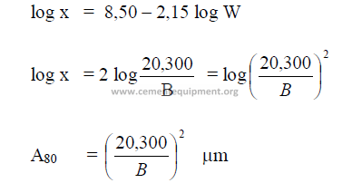
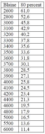
x = micron size, 80 percent passing
W = Wagner
B = Blaine
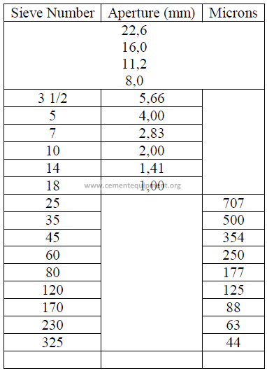
20.05 Screen Size Conversion to Micron Size
a) U. S standard sieves
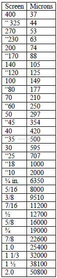
IS.O International Standard Sieves
b) I.S.O Standard International Sieves
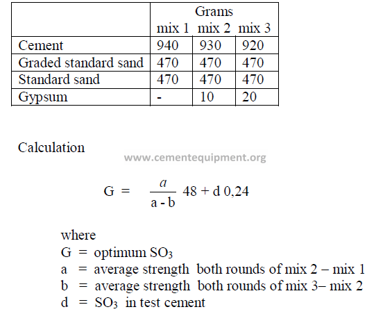
20.06 Optimum SO3 Content in Cement
Quality required for 6-cube batch:
20.07 Calculations Related to Gypsum
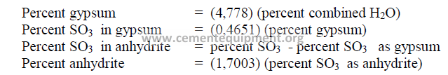
20.07 Percent Gypsum Required for Desired SO3 in Cement
where
x = percent gypsum to be addend to clinker
a = desired percent SO3 in cement
b = percent SO3 in gypsum
c = percent SO3 in clinker
20.08 Cement Fineness
20.09 Heats of Hydration
20.10 Spray Cooling with Water
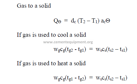
This formula applies to the cooling of gases as well as the cooling of solids
Chapter 21
GRINDING AIDS AND CEMENT FINENESS
21.01 Grinding Aid Solutions
A = water addend (l)
B = grinding aid added (l)
C = weight of solution (kg)
D = density of grinding aid as received (kg/l)
E = density of solution (kg/l)
F = percent solids in solution (expressed as decimal)
M = mill output rate (kg/h)
G = solution addition (l/h)
H = solids addition (kg/h)
I = grams solids/kg cement
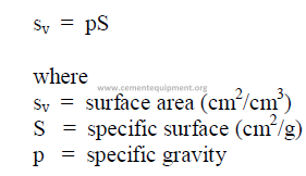
21.02 Fineness of Portland Cement by Turbidimeter (Wagner)
This formula is only applicable to cement with specific gravity of 3.13.
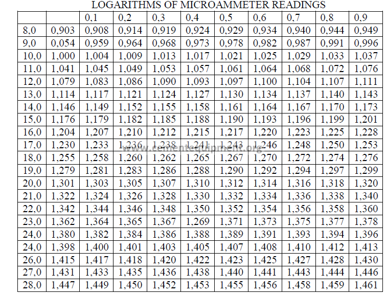
21.03 Table of Logarithms for Turbidimeter Micraammeter Readings
This table has been developed to simplify the physical testers task in calculating the
specific surface of the sample. The table should be copied and posted on or near the
turbidimeter.
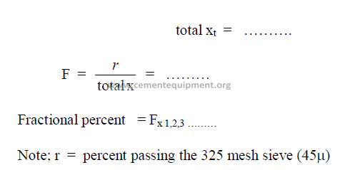
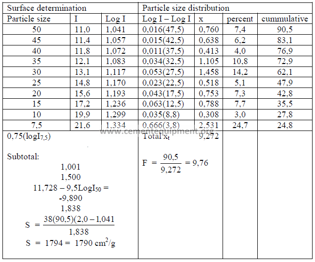
21.04 Particle Size Distribution
The turbidimeter test data can be used to calculate the particle size distribution
of a cement sample. For a detailed description of the calculations refer to the Appendix
of the specification ASTM – 115, Part 9. The work sheet below can be used in the
computation of this particle size distribution.
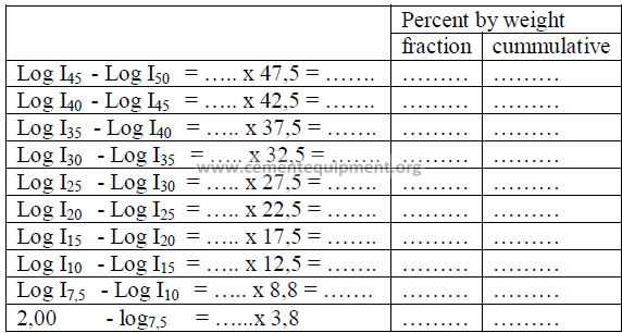
PROBLEMS AND SOLUTIONS
21.03 Determine the specific surface and the particle size distribution of the
cement sample given below. The microammeter readings from the turbidimeter are
shown in the first column under “I”.
Cement sample No: ………
Specific gravity: 3,15
Percent passing 325 sieve: 90,5
PART IV
ENGINEERING FORMULAS
Chapter 22
STEAM ENGINEERING
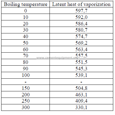
22.01 Latent Heat of Vaporization
This is the heat required to change 1 kg of boiling water to steam.
22.02 Saturated Steam Pressure
(Rankine’s formula)
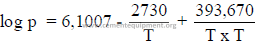
where:
p = absolute pressure (psi + 14,7)
T = absolute temperature (F + 460)
Example: What is the absolute pressure of saturated steam at 245oF?

22.03 Enthalpy
This is the heat required to change the state of water or ice.
a) Enthalpy of liquid
to change 1 kg water from 0oC to boil = 100 kcal.
b) Enthalpy of vaporization (at atmospheric pressure)
to change 1 kg of water from boil to steam = 539,1 kcal
c) Enthalpy of fusion
to change 1 kg of ice to water = 80 Btu’s
22.03 Superheated Steam
Saturated steam shows the same temperature as the water during evaporation.
Superheated steam is defined as the condition where all the water has evaporated and the
steam temperature has been raised.
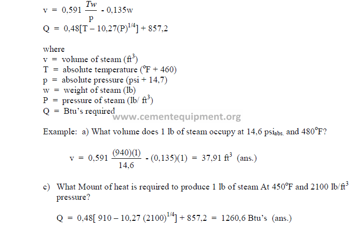
22.04 Properties of Steam
Chapter 23
ELECTRICAL ENGINEERING
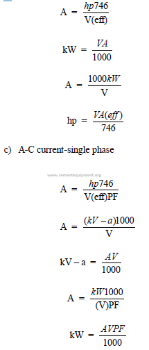
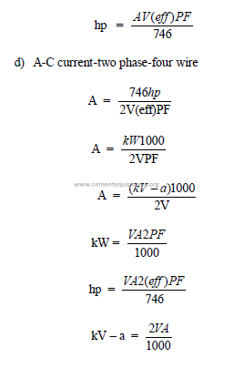
23.01 The Basic Formulas
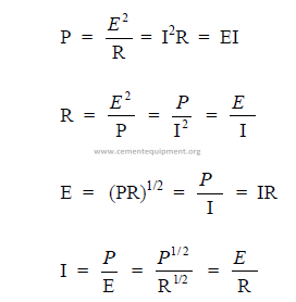
I = current (amps)
E = electromotive force (volts)
R = resistance (ohms)
P = power (watts)
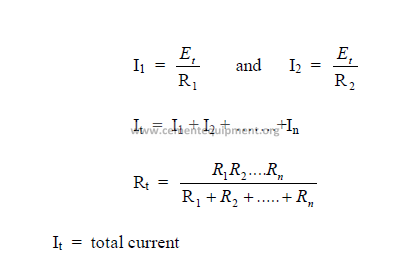
23.02 Direct Current Circuits
a) Series circuits (DC)
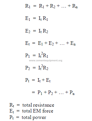
b) Parallel Circuits (DC)
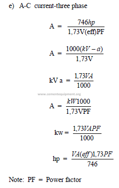
23.03 Alternating Current (AC)
Characteristic values in a cycle
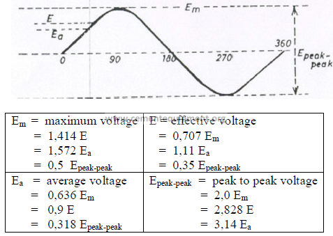
Notes; When converting AC to DC voltage, the average voltage, Ea, is used in the
calculation. The characteristic curve for current is the same as for voltage. i.e., replace the
above signs E with I to obtain the values for current. For AC circuit calculations, effective
voltage and effective current are used. Most AC measuring instruments show effective
voltages and currents.
b) Frequency of an AC cycle (hertz, cps)
Cycle frequencies are expressed in terms of cycles per second (cps) and hertz both of
which have the same meaning. In other words, if an AC has 60 hz or 60 cps, one complete
cycle takes 1/60 of a second.
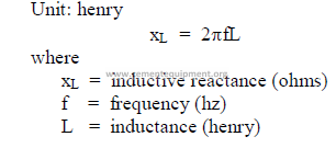
c) Inductance
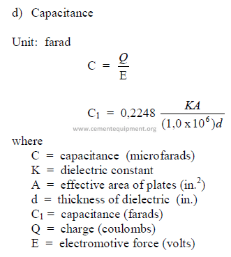
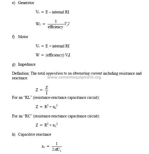
C1 = capacitance (farads)
E = electromotive force (volts)
f = frequency (hz)
I = current (amps)
R = resistance (ohms)
xL = inductive reactance (ohms)
xc = capacitive reactance (ohms)
Vt = terminal voltage
W = mechanical power output
Wl = mechanical power consumption
Z = impedance (ohms)
23.04 Useful Electrical Formulas
a) Direct current
b)
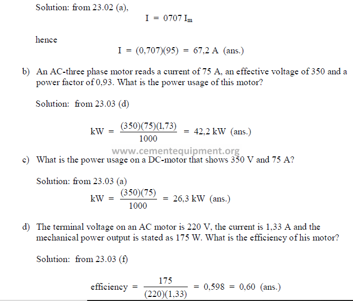
PROBLEMS AND SOLUTIONS
a) In an AC circuit, the maximum current, Im, is given as 95 A. What is the effective
amperage on this unit?
Chapter 24
FAN ENGINEERING
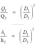
24.01 Fan Laws
Q = flow rate
p = fan static pressure
n = fan speed
h = fan horsepower
t = absolute temp. (F + 460)
d = air density
24.02 Total Efficiency of a Fan
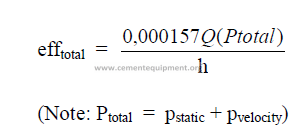
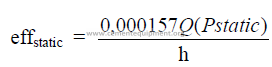
24.03 Static Efficiency of a Fan
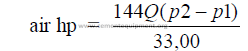
24.04 Air Horsepower
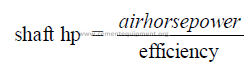
24.05 Shaft Horsepower
24.06 Similar Fans
For fans operating at the same speed and handling the same gas:
24.07 Fan Static Pressure
![]()
![]()
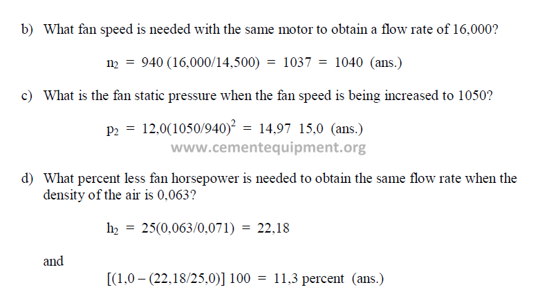
PROBLEMS AND SOLUTIONS
For all problems, given a fan with the following operating characteristics: flow rate –
14,500, horsepower – 25, fan speed – 940, static pressure – 12,0, density of air – 0,071.
a) What flow rate is obtained when the horsepower on this fan is increased to 40 hp?
![]()
![]()
Chapter 25
FLUID FLOW
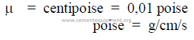
25.01 Viscosity
This is defined as the readiness at which a fluid flows when acted upon by an external
force.
Units:
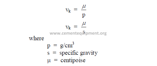
25.02 Kinematic Viscosity
Kinematic viscosity is expressed in centistokes unit
25.03 Specific Weight
This is often also referred to as the weight density and it represents the weight of a
fluid per unit volume.
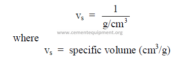
25.04 Specific Volume
This is the reciprocal of the specific weight.
25.05 Specific Gravity
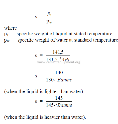
25.06 Mean Fluid Velocity
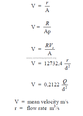
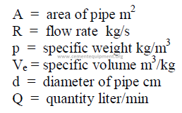
25.07 Barometric Pressure
This is the atmospheric pressure above zero absolute. Barometric pressure is always
positive.
25.08 Atmospheric Pressure
Standard conditions (0o at sea level)
atmospheric pressure = 760 mm Hg
atmospheric pressure = 101,22 kPa
Note: the kPa (kilopascal) is the official unit accepted in the International System of
units to express pressure.
25.09 Gauge Pressure
This is the pressure above atmospheric pressure. When stating gauge pressure of a gas
the plus or minus sign must also be shown to indicate pressure or vacuum.
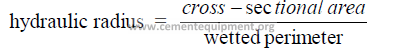
25.10 Hydraulic Radius
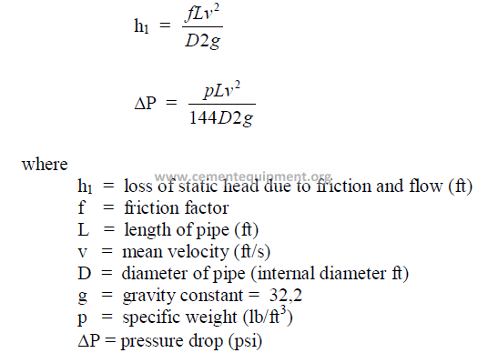
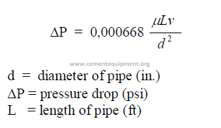
25.11 Pressure Loss In Any Pipe
These formulas apply to any liquid
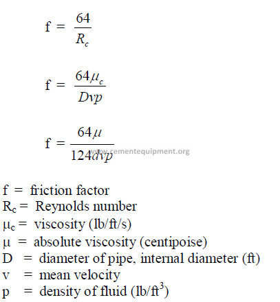
25.12 Friction Factor
25.13 Poiseuille’s Law for Laminar Flow
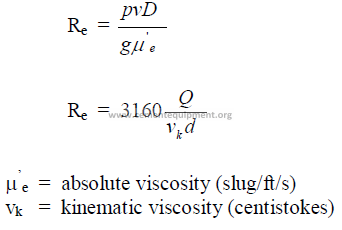
25.14 Reynolds Number
The Reynolds number expresses the nature of the flow. When Re lower than 2100 =
laminar flow; when Re higher than 4000 = turbulent flow.
25.15 Critical Velocity
In fluid flow, the critical velocity is found at a Reynold’s numbers of 2000-4000, i.e.,
when the flow changes from laminar to turbulent.
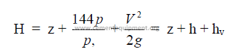
25.16 Total Head
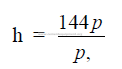
25.17 Pressure Head
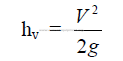
25.18 Velocity Head (Loss of Static Head)
25.19 Resistance Coefficient
Resistance to flow due to valves, elbows, etc.
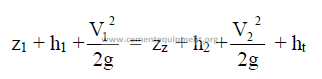
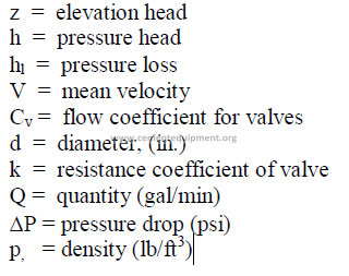
where
H = total head (ft)
z = potential head above reference level, i,e., difference in elevation (ft)
p = pressure (psi gauge)
p, = fluid dencity (lb/ft3)
V = mean velocity (ft/min)
g = gravity constant (32,2)
h = pressure head (ft)
hv = velocity head (ft)
f = friction factor
L = length of pipe
D = diameter of pipe
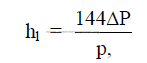
hl = head loss (see 25.21)
k = resistance coefficient
25.20 Bernoulli’s Theorem
25.21 Heat Loss
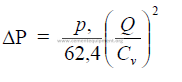
25.22 Flow Coefficient of Valves
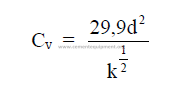
25.23 Flow Through a Valve
Condition: viscosity similar to water.
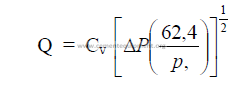
25.24 Pressure Drop Through Valves
25.25 Flow Through Pipe
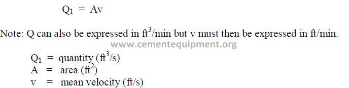
25.26 Velocity vs. Cross-Sectional Area
25.27 Potential Energy for Fluids
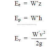
25.28 Total Energy of a Liquid
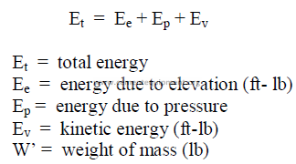
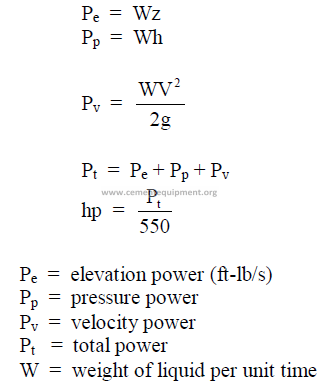
25.29 Power of a Liquid
Rate at which a liquid can do work.
25.30 Flow Trough Nozzles and Orifice
25.31 Flow Coefficient
25.32 Flow Through Pipes
25.33 Flow Through Rectangular Weir
25.34 Flow Through Triangular Weir
25.35 Gas Flow Measurements
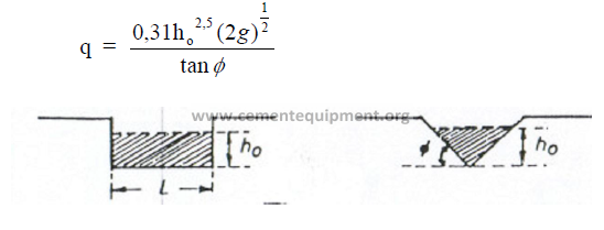
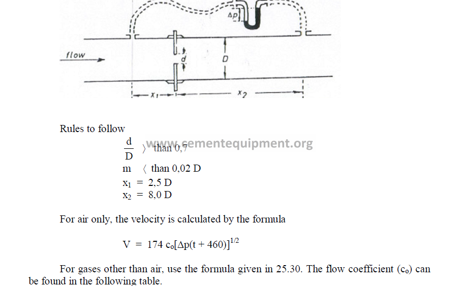
a) Location of sampling ports
For accurate measurements, the sample ports should be located from one half to two
duct diameters upstream and two to eight duct diameters downstream from disturbances such
as bends, reductions, and others.
b) To obtain accurate results, a minimum of 12 traverse points are required as the
duct cross section as shown in the following sketch:
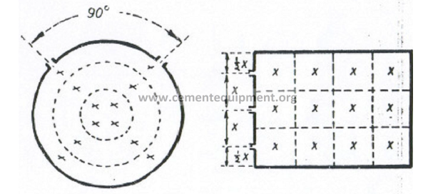
c) Traverse points for circular stacks
To cover equal areas in a circular stack or duct and thus obtain an accurate traverse,
the following table can be used to locate individual points in the traverse.
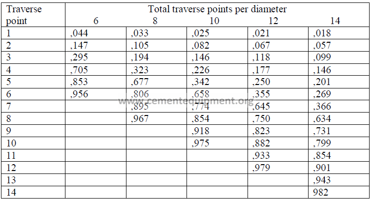
Numbers indicated are fractional distances of the diameter.
Example: When a 12-point traverse has to be make on a stack having an inside wall
diameter of 72 inches, where must the fourth traverse point be located?
Solution: (0,177)(72) = 12,7 in. from the inside wall (ans.)
25.36 Pitot Tube Measurements
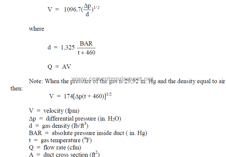
25.37 S-Tube Measurements
The S-Tube operates on the same principle as the pitot tube but is primarily used to
measure gases that contain dust particles which would have the tendency to plug a pitot tube.
To use the S-tube, the tube factor (cs) has to be known or be determined by calibration.
Normally, cs = 0,85 – 0,90. The velocity is calculated by the following formula where “Dp”
and “J” have the same meaning as in the preceding formula.
![]()
![]()
25.38 One-Point Traverse
In cases where only approximate flow rate determinations are required, a one-point
reading of the differential pressure can be made in the center of a circular duct. However, the
calculated velocity (V) has to be multiplied by a factor of 0,91 to obtain the approximate
average velocity in the duct.
25.39 Conversion of Flow Rates
25.40 Flow Determination with Orifice Plate
In small diameter pipes, an orifice plate is usually more convenient employed than a
pitot tube to measure flow rates.
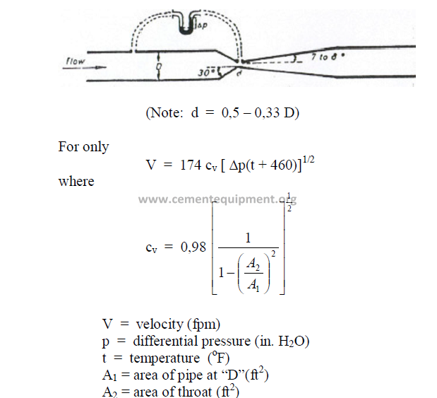
25.41 Ventury Meters
Chapter 26
HEAT TRANSFER
Symbols used:
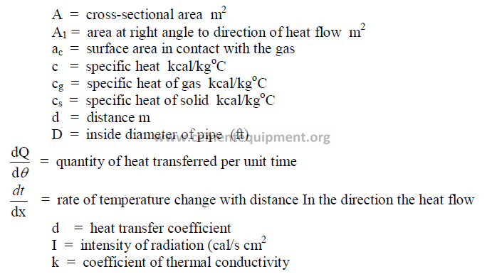
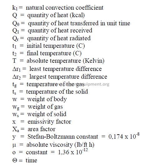
26.01 Heat Required for a Temperature Change
![]()
![]()
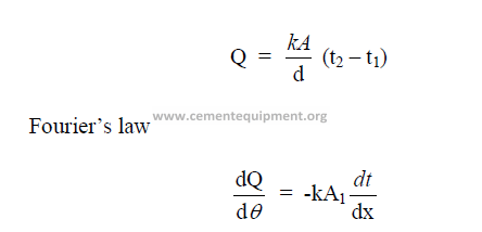
26.02 Conduction
This is defined as the transfer of heat within a substance or from one substance to
another while they are in contact with each other.
26.03 Convection
This is defined as the transfer of heat by the motion of the particles of the heated
substance itself. Convection occurs only in liquids and gases by circulation.
![]()
![]()
26.04 Radiation
This is defined as the transfer of heat from one body to another without the two being
in contact with each other.
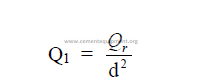
Stefan-Boltzman law
This law expresses the relationship between the intensity of radiation and the
absolute temperature of the body. For a “black” body
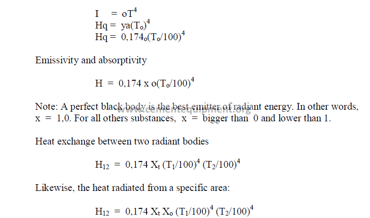
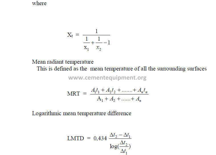
26.05 Nusselt Number (Nu)
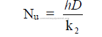
26.06 Prandl Number (Pr)
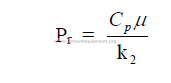
26.07 General Heat Transfer Equations
26.08 Temperature Equivalents
Chapter 27
PHYSICAL CHEMISTRY
GASES
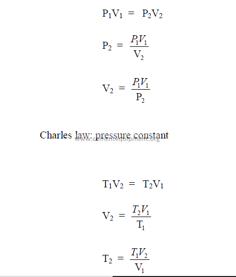
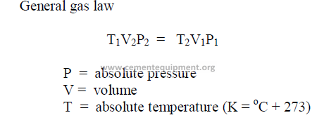
27.01 Gas Laws
These well known laws apply to the English as well as the metric system of units.
27.02 Gas Law Constant

27.03 Avogadros Law
A mole of any substance contains the same number of molecules. Equal volumes of all
gases under the same temperature and pressure conditions contain the same number of
molecules:
The number of molecules in a mole of any substance is constant. Avogadro’s
number = 6,024 x 10 13 (at standard condition). Also: 22,4 liters of any gas at standard
condition contains the above number of molecules.
27.04 Density of a gas
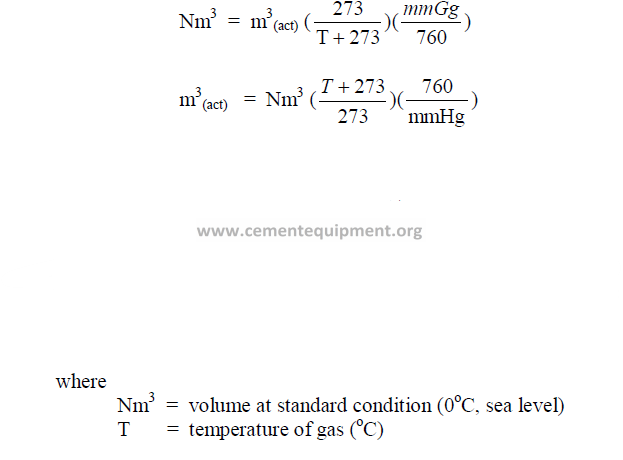
27.05 Standard Condition of a gas
At 0oC, 1 atm.
27.06 Normal Density of a gas
27.07 Molecular Weight of Gases
27.08 Density Changes of Gases
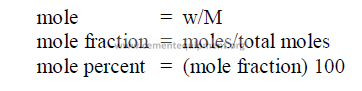
27.09 Moles
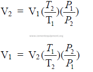
27.10 Volume Changes of a Gas
SOLUTIONS
27.11 Weight Percent of Solutions
This is defined as the number of grams of solute per 100 grams of solvent.
Example: 14 grams of salt dissolved in 100 grams of water fives 114 gram of
solution. Thus,solute = 14/114 (100) = 12,28 percent
In many instances, the weight of solute is expressed also in terms of the volume of
solution ,e.g., 14 grams of salt per liter of solution.
27.12 Mole Fraction of a Solution
This is defined as the number of gram molecules (moles) of solute per total number of
moles contained in the solution.
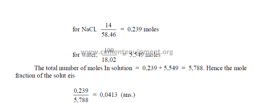
Example: 14 grams of NaCl (sodium chloride) are dissolved in 100 grams of water.
(Note: molecular weight of NaCl = 58,46 and water = 18,02). Thus,
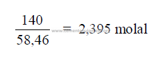
27.13 Molality of a Solution
The number of mole sof solute per liter of water.
Example: 140 grams of NaCl per 1000 grams of water.
27.13 Molarity of a Solution
A molar solution contains one mole of solute per liter of solution.
Example: The molecular weight of NaCl (sodium chloride) is 58,46. Thus a molar
table salt solution contains 58,46 grams of NaCl per liter of solution.
SOLIDS
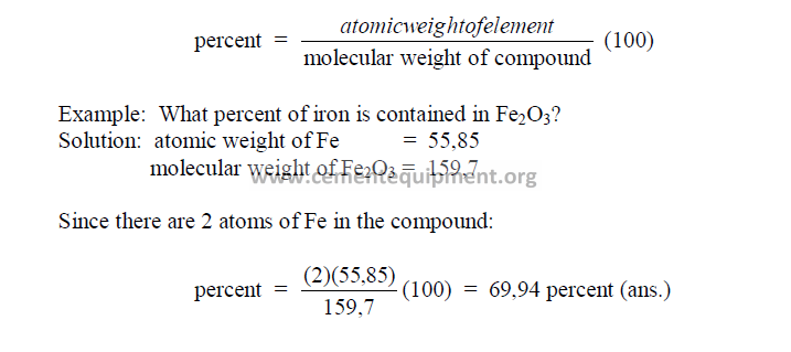
27.14 Percent of an Element Contained in a Compound
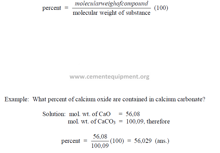
27.15 Percent of a Compound Contained in a Substance
27.16 Weight Problems
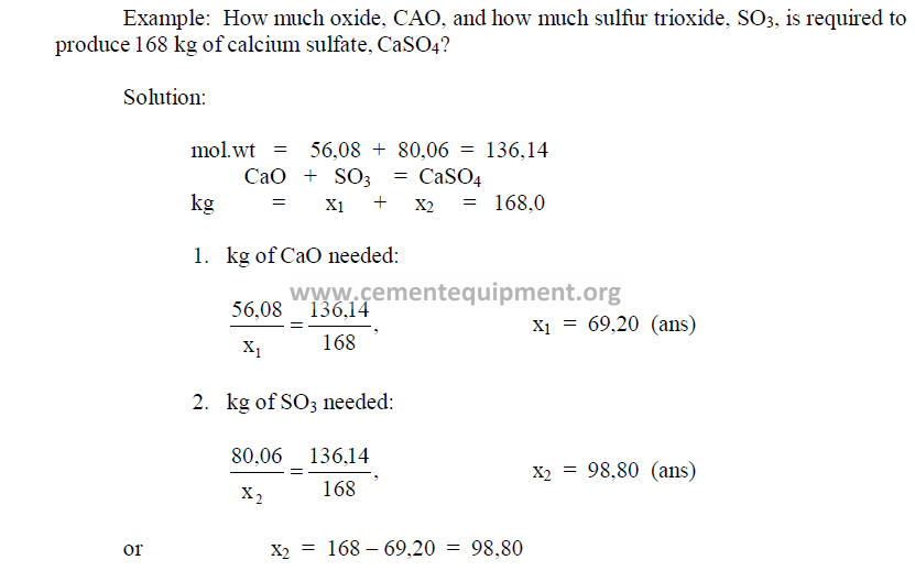
Calculations involving weight and mixture problems can best be solved by writing the
problem in the form of a chemical equation as shown in the following example.
Chapter 28
PHYSICS
28.01 Newton’s Law of Gravitation
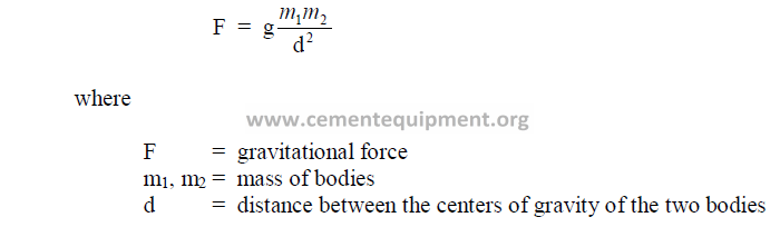
g = gravitational constant = 981 cm/s2
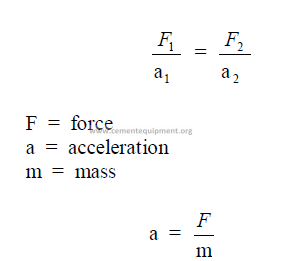
28.02 Acceleration – Forces
The absolute unit is the dyne which expresses the force that produces acceleration, i.e.,
a change in momentum on a body at rest or in motion.
dyne = the force required to produce an acceleration of 1cm/s2 in gram mass.
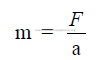
28.03 Mass of a Body
Mass expresses the quantity of matter. The metric unit for mass is the gram.
28.04 Weight of a Body
Weight is defined as the force with which a body is attracted toward the earth
w = mg
28.05 Work Done
W = Fs
Work is expressed as the product of the force acting on a body and the distance the
body has moved against the resistance.
W = erg = force of one dyne through one centimeter
![]()
![]()
= g/cm = 980 erg
28.06 Power
The time rate at which work is done.
28.07 Molecular Heat of Gases
This is defined as the heat required to raise the temperature of one gram-mole of a gas
one degree Celsius.
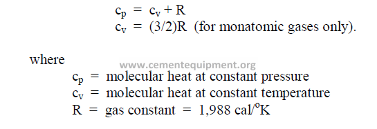
28.08 Molecular Heat of Solids
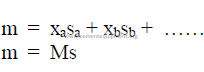
where
m = molecular heat of solid
M = molecular weight
s = specific heat
x = atomic weight
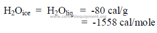
28.09 Latent Heat of Fusion
This is defined as the heat required to obtain a change of state without a temperature
change in the substance. Latent heat of fusion is expressed in either cal/mol, cal/g.
Example
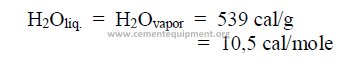
28.10 Latent Heat of Evaporation
This is defined as the heat required to change a substance from a liquid to a gaseous
state without a change in temperature. This is also known as the enthalpy of evaporation.
Example
28.11 Heat of Formation and Reaction
This is defined as the heat units absorbed or evolved in a chemical reaction to form
one mole of a substance.
AB + CD = AC + BD + h
When the heat of formation of individual compounds is known, e.g.,
A + B = AB + a, etc.,
then
AB + CD = AC + BD –a – b + c + d
and
h = c + d – (a + b)
where
A,B,C = compounds weight
a,b,c = heat of formation
h = heat of reaction
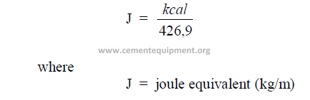
28.12.1Joule Equivalent
This is the mechanical equivalent of heat
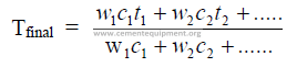
28.13 Temperature of a Mixture
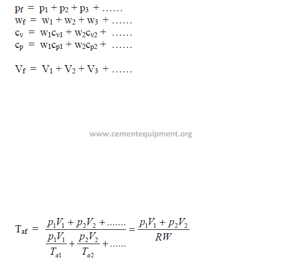
28.14 Gas Mixtures
 4
4
28.15 Gas Constant, R
For air = 29,3
For O2 = 26,5
28.16 Friction Coefficient
This is defined as the ratio of the force required to move one body over the other to the
total force pressing the two bodies together
28.17 Moment of Force-Torque
This is the force that producers rotation about an axis.
L = Fd
where
L = torque (dyne-cm)
F = force that produces rotation about center (dyne), and
d = perpendicular distance from the line of action of the force to the axis (cm).
Chapter 29
PSYCHROMETRY
29.01 Basic Psychrometric Equation
29.02 Wet Bulb Depression
The wet bulb depression is expressed:
wet bulb depression = t – t’
29.03 Relative Humidity
p = partial pressure of water vapor at dry bulb temperature
p’ = saturation pressure of water vapor at wet bulb temperature
P = total barometric pressure
t’ = wet bulb temperature
t = dry bulb temperature
px = saturation pressure of water vapor at dry bulb temperature
29.04 Dew Point
When the partial pressure of water vapor at a dated temperature equals the saturation
pressure of water vapor at the same temperature, the air is saturated, i.e., the dew point has
been reached.
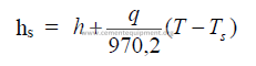
hs = saturation humidity, dew point
h = absolute humidity
q = 0,24 + 0,45 h = heat capacity
T = dry bulb temperature (oF)
Ts = saturation temperature (oF)
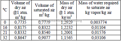
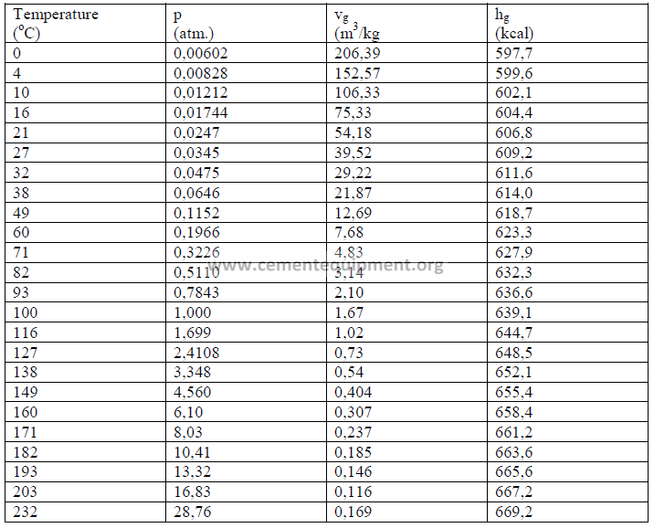
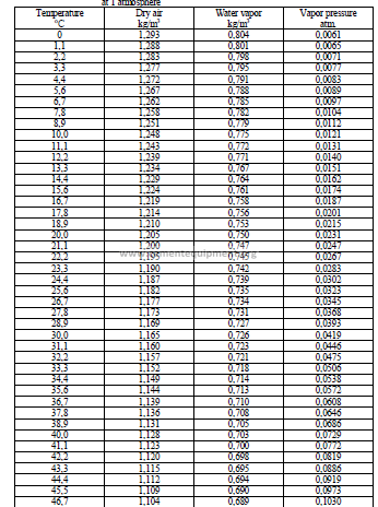
29.05 Properties of Air and Water Vapor
PART V
EMISSION CONTROL AND PLANT
EQUIPMENT
Chapter 30
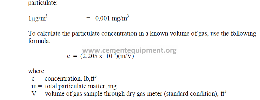
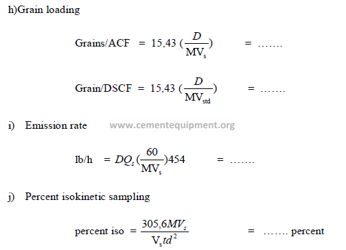
TEST FOR PARTICULATE EMISSIONS
Formulas used to determinate the particulate emission rate are given. They apply to
tests performed with a dry gas meter. For details of the testing procedures, the reader is
advised to refer to “Standard Performance for Stationary Sources”, Federal Register,
Dec.23,1971.
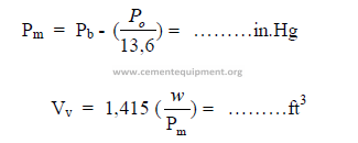
30.01 Data needed for Stack Testing
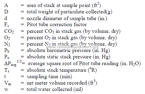
30.02 Summary of Results
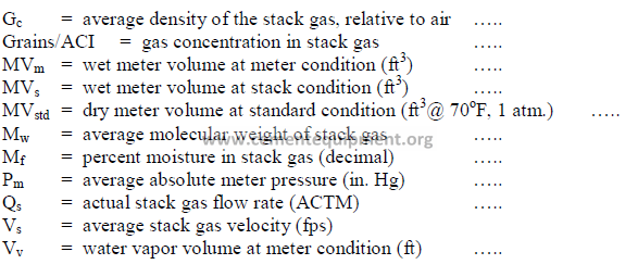
30.03 Calculations
a) Conversion of water collected to gas at meter conditions
(for gas meter, internally corrected to 70oF)
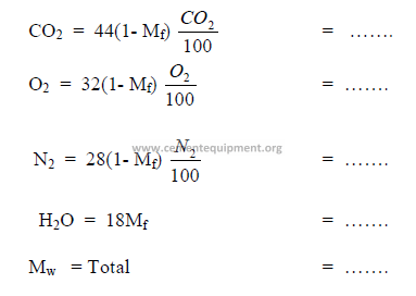
b) Percent moisture in flow gas
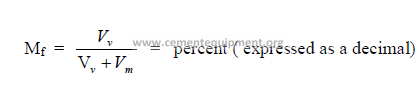
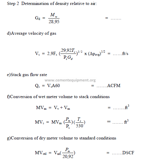
c)Density of gas relative to air
Step 1 Determination of molecular weight of gas:
Chapter 31
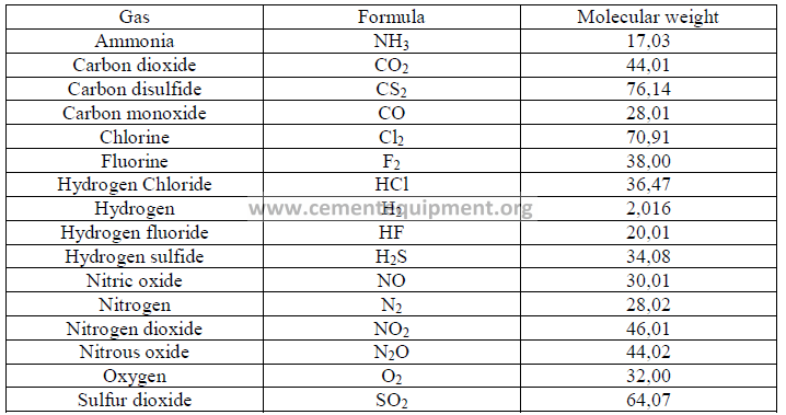
USEFUL DATA FOR EMISSION CONTROL
31.01 Molecular Weights of Selected Gases
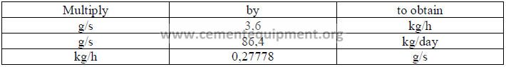
31.02 Conversion Factors for Emission Rates
Chapter 32
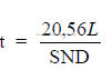
STORAGE AND TRANSPORT EQUIPMENT
32.01 Drum Dryers
a) Evaporation rate
b) Dryer volume
![]()
![]()
c) Specific rate of evaporation

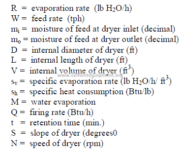
d) Specific heat consumption
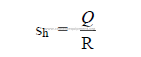
e) Feed retention time (for approximation only)
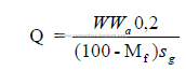
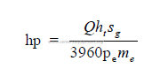
32.02 Slurry Pumps
a) Specific gravity of slurry
The specific gravity of the slurry can be obtained directly from the table given in 3.01
or, when the specific gravity of the dry solids is not 2.70, can be calculated by the following
formula:
b) In 3.04 a formula is given that users the pulp density of the slurry as a variable.
Another formula that is useful:
c) Power required for pumping
d) Friction factor for pipe lines
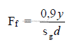
Note: Use 0,85 if y is not known.
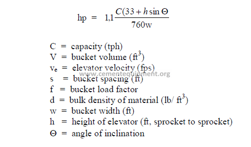
32.03 Bucket Elevators
a) Elevator capacity
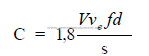
Note: f = normally 0,45 to 0,65
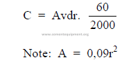
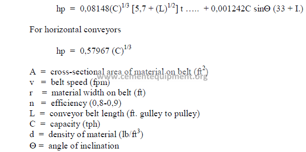
32.04 Belt Conveyors
a) Conveyor capacity
b) Horsepower required for belt conveyor
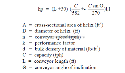
32.05 Screw Conveyors
a) Screw conveyor capacity
C = 0,005625 ADnkd
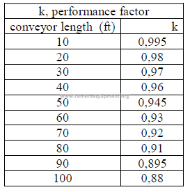
b) Horsepower required
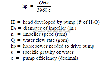
32.06 Water Pumps
a) Centrifugal pump head
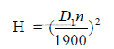
b) Horsepower required to pump water
32.07 Storage Tanks
a) Contents in vertical cylindrical tanks
![]()
![]()
Note: This formula applies only to flat bottom tanks.
b) Contents in cones
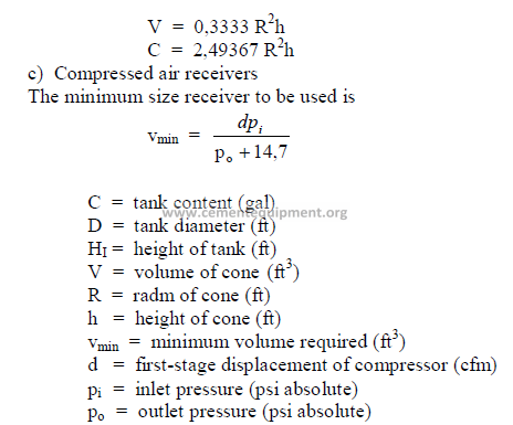
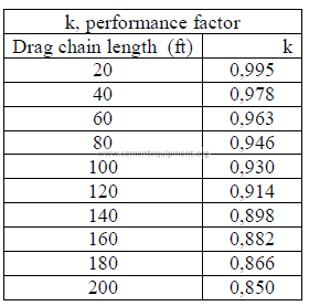
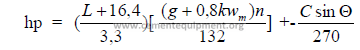
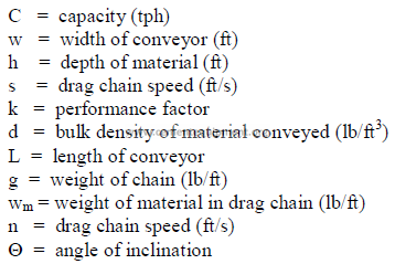
32.08 Drag Chains
a) Drag chain capacity
C = 1,8 whskd
b) Horsepower required
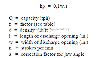
32.09 Jaw and Gyratory Crushers
a) Jaw crusher capacity
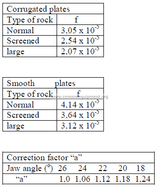
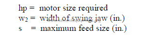
Q = fdlwjna 0,8
FACTOR “f”
b) Horsepower required
32.10 Stack and Chimneys
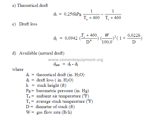
P A R T VI
APPENDIX
Section A
MATHEMATICS
ALGEBRA
A1.01 Exponents
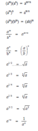
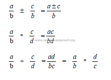
A1.02 Fractions
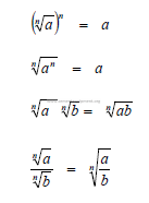
A1.03 Radicals
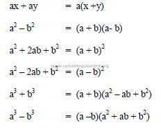
A1.04 Factoring
A1.05 Scientific Notations
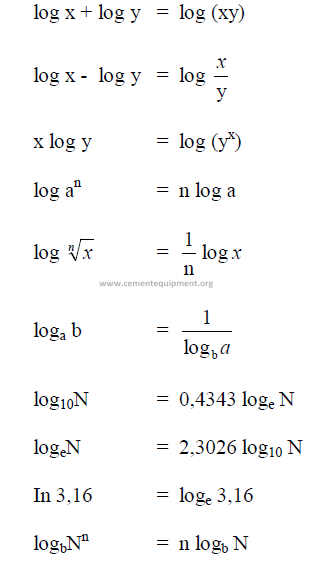
A1.06 Logarithms
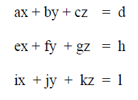
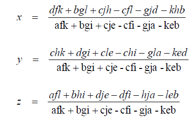
A1.07 Determinants
Solutions
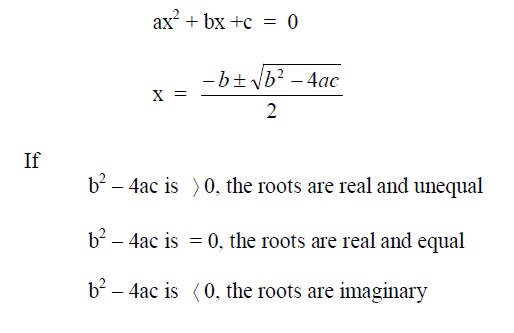
A1.08 Quadratic Equation
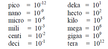
A1.09 Powers of ten
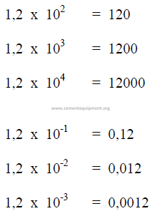
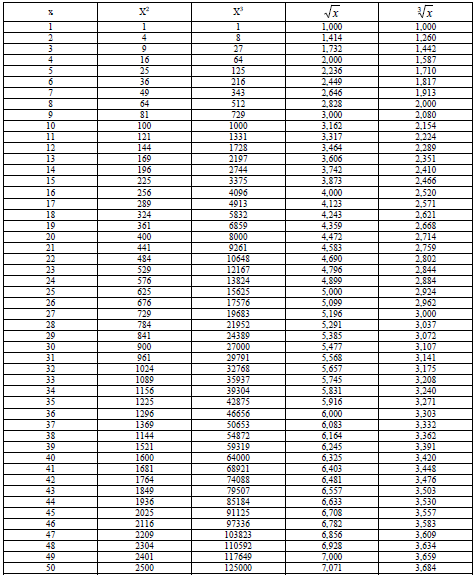
A1.10 Power and Roots
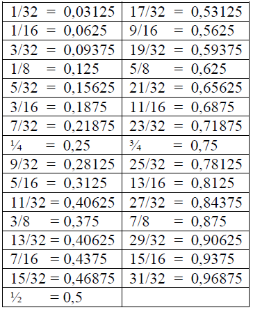
A1.11 Fractions and Decimal Equivalents
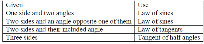
TRIGONOMETRY
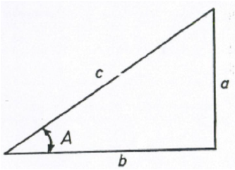
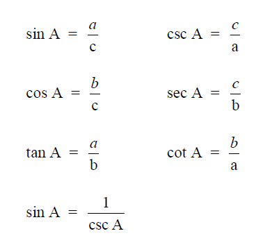
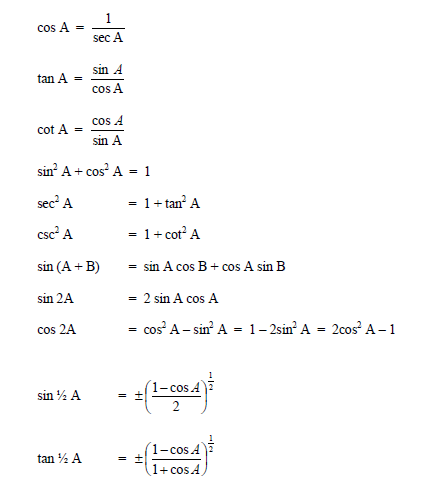
A2.01 Right Triangle
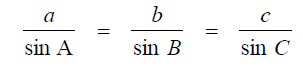
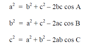
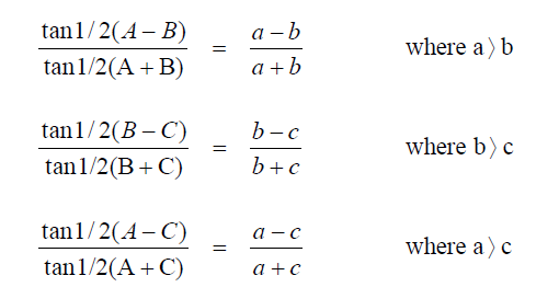
A2.02 Any Triangle
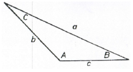
Law of Sines
Law of Cosines
Law of Tangents
Newton’s Formula
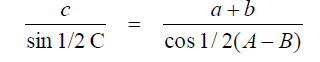
Tangents of Half Angles
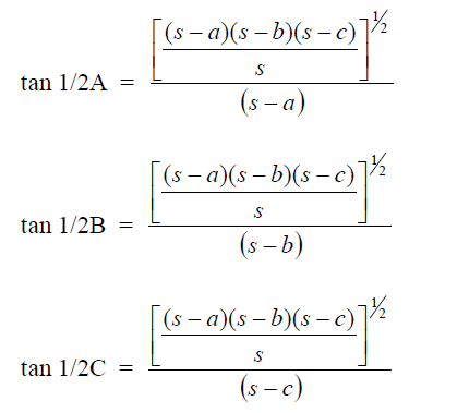
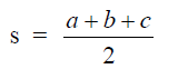
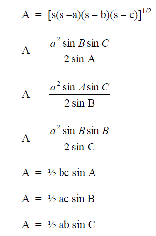
SOLUTIONS OF TRIANGLES
Area
STATISTICS
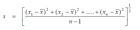
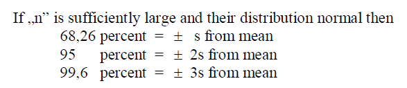
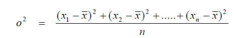
A3.01 Standard Deviation
When calculating the standard deviation of a population larger than 30 use the formula
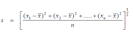
For samples whose total number is less than 30, (ná 30) use
A3.02 Variance
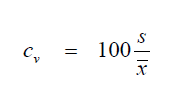
A3.03 Coefficient of Variation
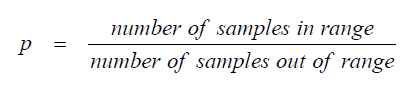
A3.04 Relative Frequency
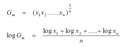
A3.05 Geometric Mean
A3.06 Least Squares
To determine the corelations between two variables solve the simultanous equations
for a and b
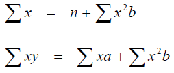
where x and y are the values of the plotted variables and n = the number of samples.
After these values have been found, the best line to fit the plotted points (least square
equation) becomes:
Y = a + bx
A3.07 Coefficient of Correlation
The coefficient of correlation is a measure of the proximity of the ploted points on a
graph to the straight line represented by the least square equation
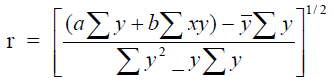
where
When „r” approaches unity, there is a good correlation, when is approaches zero, there
exists too wide a scatter to obtain a correlation.
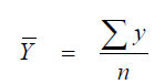
Symbols used (in A3.01 to A3.05)
FINANCES
A4.01 Compound Interest
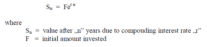
Example: What is the value after 21 years when $1250 is invested at a compound
interest rate of 5,5 percent?
![]()
![]()
A4.02 Total Annual Cash Flow
C = I + D
C = R – E
C = P + D
where
C = annual cash flow
I = annual income
D = annual depreciation
R = annual expenses
P = after tax profit
A4.03 After Tax Profit
P = (100 – t)(R –E)
where
P, R, and E have the same meaning as in 4.02 and
t = tax rate (expressed as a decimal)
Example: A company had $ 25 million in revenues and $ 0,95 million of expenses in
one year. What is the after tax profit when the tax rate assessed is 50 percent?
![]()
![]()
A4.04 Straight Line Depreciation
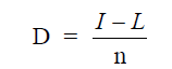
where
D = straight line depreciation
I = initial investment value
L = expected salvage value at end of useful life
n = expected useful life
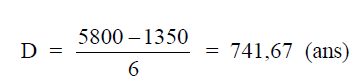
Example: An office copier is being purchased for a cost of $5800. Its useful life is
expected to be six years; after these six years its salvage value is estimated at $1350. What is
the annual depreciation on this copier when the straight line depreciation on this copier when
the straight line depreciation method is used?
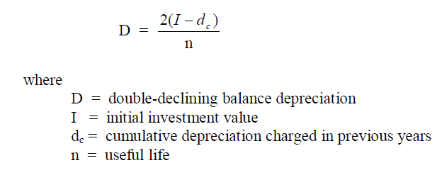
A4.05 Double-declining Balance Depreciation
A4.06 Sum-of-Years Digit Depreciation
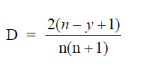
where
D = sum-of-years digit depreciation
n = useful life
y = consecutive number of years from start of investment to year where D
applies.
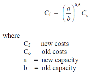
A4.07 Sixth-Tenth Factor
This factor is used to estimate the costs to replace an old by a new identical unit.
A4.08 Value of an Investment After Depreciatio
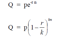
where
Q = final value
p = initial value when new
r = rate of annual depreciation (decimal)
n = number of years
k = number of time per year depreciation is figured
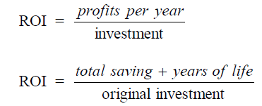
A4.09 Return on Investment, ROI
A4.10 Simple Compound Interest
![]()
![]()
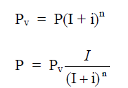
A4.11 Present Worth
Worth after n years
A4.12 Equal Payment Series Compound Amount
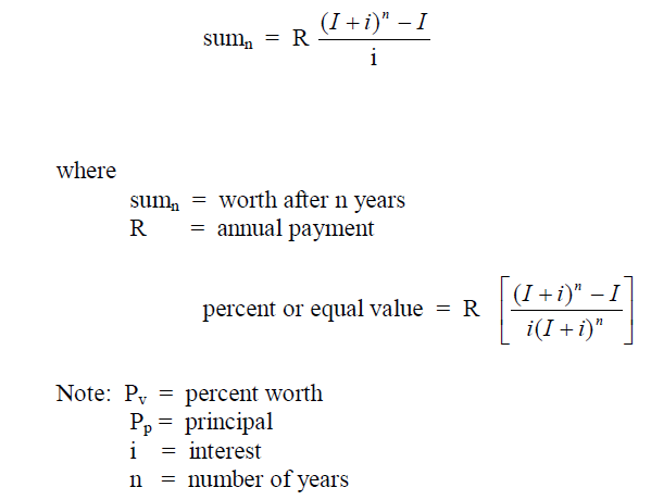
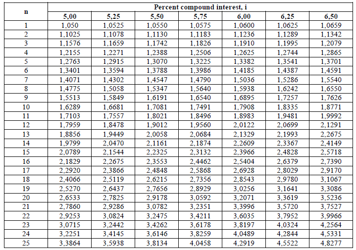
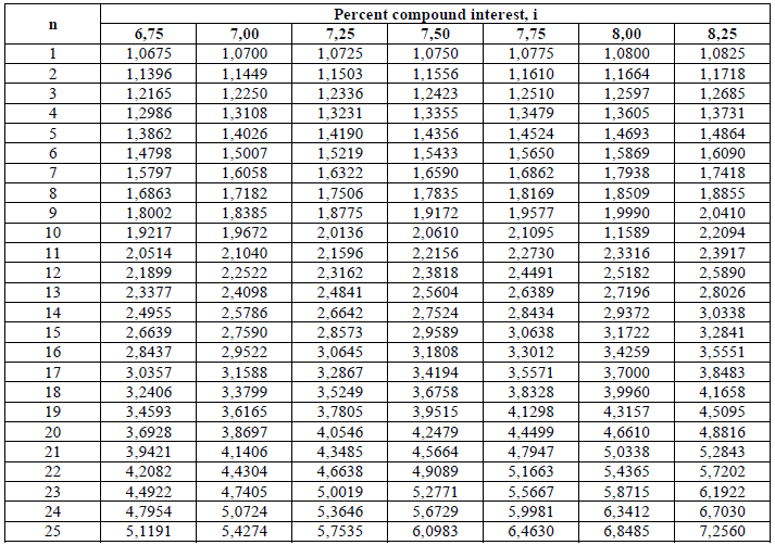
A4.13 Compound Interest Factors (I + i)n
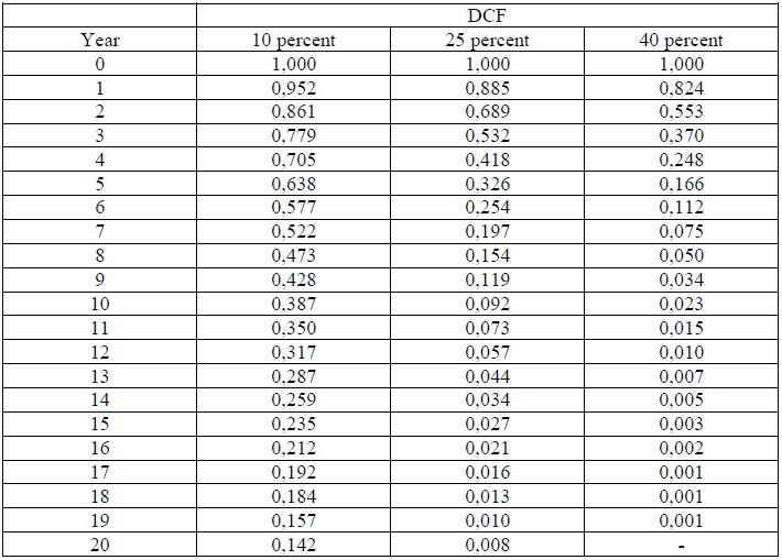
A4.14 Discouted Cash Flow Factors
A4.15 Deposit Calculation
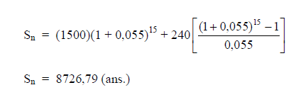
This type of calculation is used to determine the value of an account after „n” years
when an annual deposit of „l|” is made to the account.
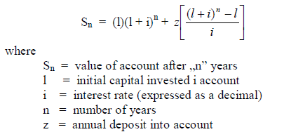
Example: What is the account balance after 15 years when the initial deposit is
$150 000 , na annual amount of $240,00 is deposited, and the account pays 5,5% compound
interest?
SAFETY FORMULAS
A5.01 Accident Frequency Rate
Accident frequency rate is defined in terms of number of accsidents per milion manhours
worked.
f = frequency rate
n = number of accsidents during period under investigation
h = number of man-hours worked during the same period
A5.02 Severity rate
Accident severity rate is defined in terms of the number of days lost due to accidents
per 1000 man-hours worked.
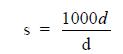
where
s = severity rate (days lost/ 1000 man-hours)
d = days lost in period
h = total man-hours worked in same period
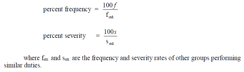
A5.03 Safety Performance
An individual group, department, or plant safety performance can be stated in terms of
another’s group known standard performance as follows:
PLANE AND SOLID GEOMETRY
Plane Figures
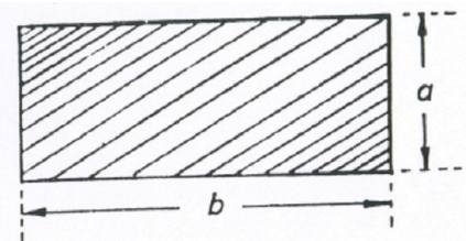
A6.01 Rectangle
area = ab
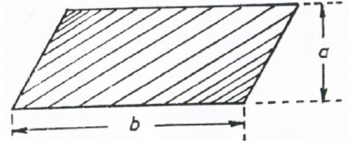
A6.02 Parallelogram
area = ab
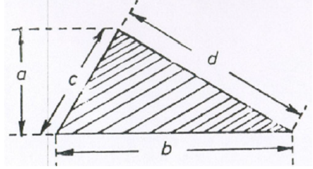
A6.03 Triangle
area = 0,5 (ab)
Let x = 0,5(b + c + d)
then
![]()
![]()
A6.04 Circle
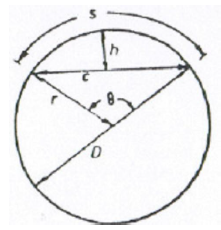
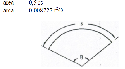
A6.05 Circular Sector
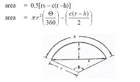
A6.06 Circular Segment
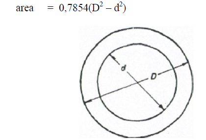
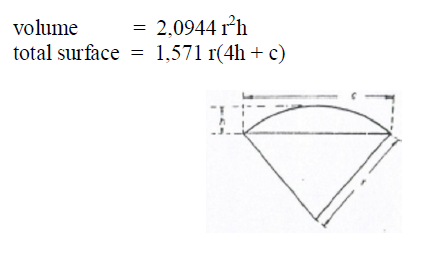
A.07 Circular Ring
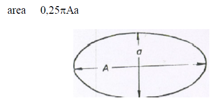
A6.08 Ellipse
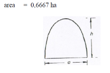
A5.09 Parabola
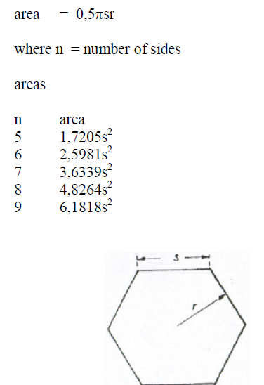
A6.10 Polygon
A6.11 Trapezoid
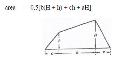
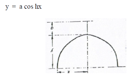
A6.12 Catenary
Solids
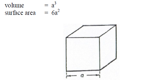
A6.13 Cube
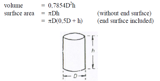
A6.14 Cylinder
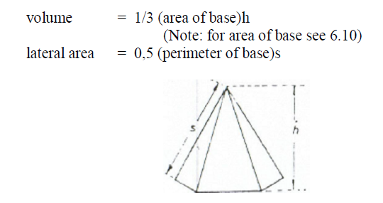
A6.15 Pyramid
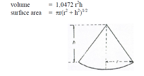
A6.16 Cone
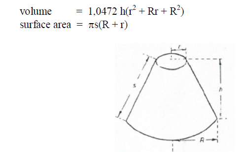
A6.17 Frustum of a Cone
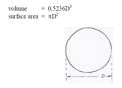
A6.18 Sphere
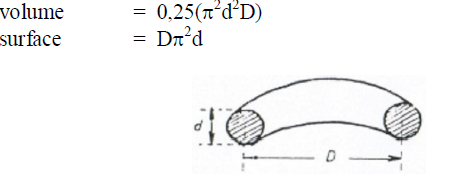
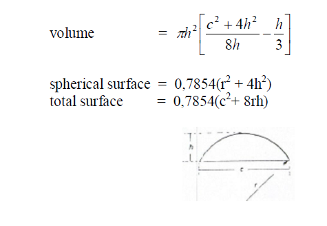
A6.19 Segment of a Sphere
A6.20 Sector of a Sphere
A6.21 Torus