Quick answer
Repeated motor-current spikes on a cement screw conveyor during silo extraction usually indicate changing mechanical resistance or unstable material loading rather than an electrical fault alone. Separate material compaction, flooded inlet, bent or rubbing screw flight, hanger-bearing drag, poor alignment, buildup, downstream restriction and drive problems by trending current against process conditions and inspecting the conveyor in a controlled sequence.
Problem / job
Motor current rises sharply, trips intermittently, or oscillates while the screw conveyor extracts cement or raw meal from a silo.
Evidence
Capture motor current, screw speed, silo level, aeration status, feeder/gate position, downstream equipment status, material condition and the exact time of every current spike.
Decision
Determine whether the load increase comes from excess material feed, internal mechanical drag, restricted discharge, unstable bulk flow or a drive/electrical defect before changing protection settings.
As-found evidence capture
Before stopping the conveyor, record whether the spikes occur continuously or only during silo aeration, high silo level, startup, gate opening, downstream stoppage, or a particular product. Compare the operating current with a known stable period at similar throughput. Note whether the current rises gradually, jumps suddenly, or fluctuates rhythmically. These patterns help distinguish changing material load from rotating mechanical interference.
Check for abnormal noise, vibration, casing movement, hot bearings, dust leakage and evidence of product buildup. Confirm whether the conveyor is horizontal or inclined, its approximate fill condition, and whether any process change was made before the problem started. Do not increase overload settings or bypass motor protection to keep production running; the current rise is evidence that should be explained.
Seven-step diagnostic workflow
1. Correlate current spikes with material-feed conditions
Trend motor current against silo discharge gate position, rotary feeder or slide-gate opening, aeration timing and screw speed. If the current spikes immediately after a gate opens further or aeration increases, the screw may be receiving more material than it can transport steadily. A flooded inlet can bury the screw and increase torque rapidly.
2. Verify downstream availability
Confirm that the discharge chute, elevator, airslide, weigh feeder or next conveyor is accepting material. A restricted outlet can cause the screw trough to fill progressively until current rises. Inspect for plugged chutes, collapsed flexible connections, closed valves, slow downstream equipment or material backing up into the screw.
3. Check bulk-flow stability at the silo outlet
Intermittent arches, ratholes or dense slugs can create alternating low-load and high-load periods. Review aeration operation and outlet condition. If current spikes are synchronized with aeration pulses or sudden material avalanches, stabilize silo extraction rather than treating the motor as the root cause.
4. Inspect screw-to-casing clearance and alignment
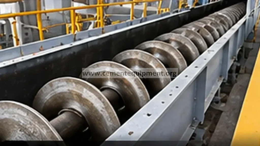
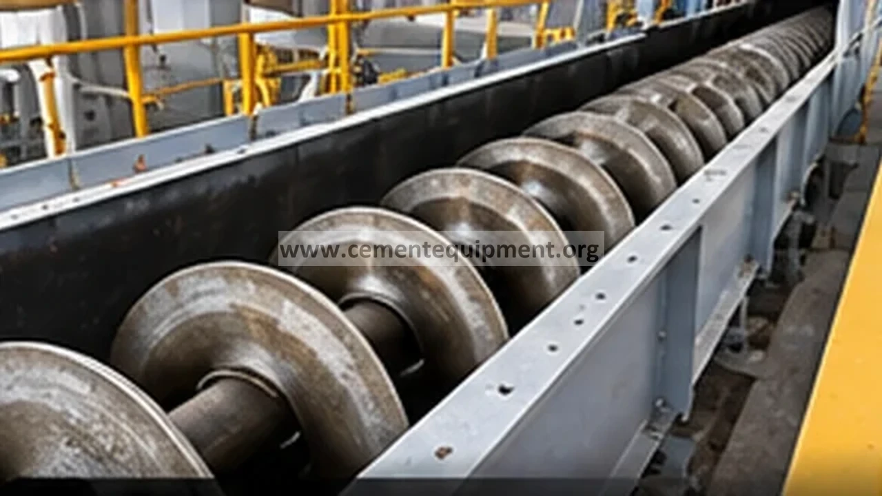
After proper isolation and lockout, inspect the screw for rubbing marks, bent pipe sections, distorted flights, damaged trough sections and coupling misalignment. Look for shiny contact marks or localized wear that indicate metal-to-metal interference. Long screws are especially sensitive to poor support, thermal distortion and misaligned hanger bearings.
5. Inspect bearings, hangers and seals
Rotate the screw manually where the OEM procedure allows and check bearing freedom. A seized or contaminated hanger bearing can create a high localized drag load. Inspect end bearings, hanger bearings, seals and lubrication condition. Compare bearing temperatures and vibration before dismantling so the evidence is preserved.
6. Inspect buildup and hardened deposits
Cement and raw meal can compact around the screw shaft, flights, trough corners and discharge end. Moisture ingress or long idle periods can turn loose powder into hard deposits. Remove buildup using the approved maintenance method and verify that no hardened mass remains in the clearance zone.
7. Verify the drive and electrical system
If the mechanical and process checks are satisfactory, inspect gearbox condition, coupling alignment, motor terminals, phase-current balance and supply voltage. Compare phase currents under load. An electrical defect can raise current, but a balanced current increase that follows throughput usually points first to mechanical or process loading.
Evidence-to-decision table
| Observed evidence | Most useful next check | Decision direction |
|---|---|---|
| Current rises after gate opening or stronger aeration | Material feed rate and inlet flooding | Control incoming solids load before changing motor settings |
| Current climbs gradually during operation | Downstream restriction and trough filling | Clear the outlet path and verify downstream capacity |
| Sharp periodic spikes with abnormal noise | Flight/casing contact, coupling and hanger alignment | Inspect for rotating mechanical interference |
| High current after long idle period | Compacted material and hardened buildup | Clean and restore internal clearance |
| Unequal phase currents with normal mechanical condition | Motor terminals, supply and winding condition | Escalate to electrical diagnosis |
Verification and return-to-service criteria
Return the conveyor to normal service only after the internal path is clear, bearings rotate freely, the screw does not contact the casing, the downstream path is open and the process feed is controlled. Run the conveyor first under the OEM-approved no-load or low-load condition where applicable, then under a representative production load. Motor current should stabilize without unexplained spikes, abnormal noise, rapid temperature rise or repeated overload alarms.
Document the as-found current trend, identified cause, corrective work and post-maintenance current under comparable throughput. This creates a baseline for future condition monitoring and prevents repeated trial-and-error interventions.
Common mistakes and repeat-failure traps
Do not increase overload protection to hide a torque problem. Do not assume the motor is undersized until the conveyor is checked for flooding, buildup and mechanical drag. Do not clean only the discharge chute if the trough remains packed. Do not replace bearings without checking shaft alignment and support condition. Finally, do not compare motor current at different throughputs and conclude that a change is abnormal without normalizing the operating condition.
Related Infinity guides
Build a stronger cement maintenance library
The Infinity for Cement Organization technical package contains 900+ technical files for cement professionals. It is a one-time $249.99 purchase, with instant download immediately after payment and lifetime updates forever at no additional cost.