
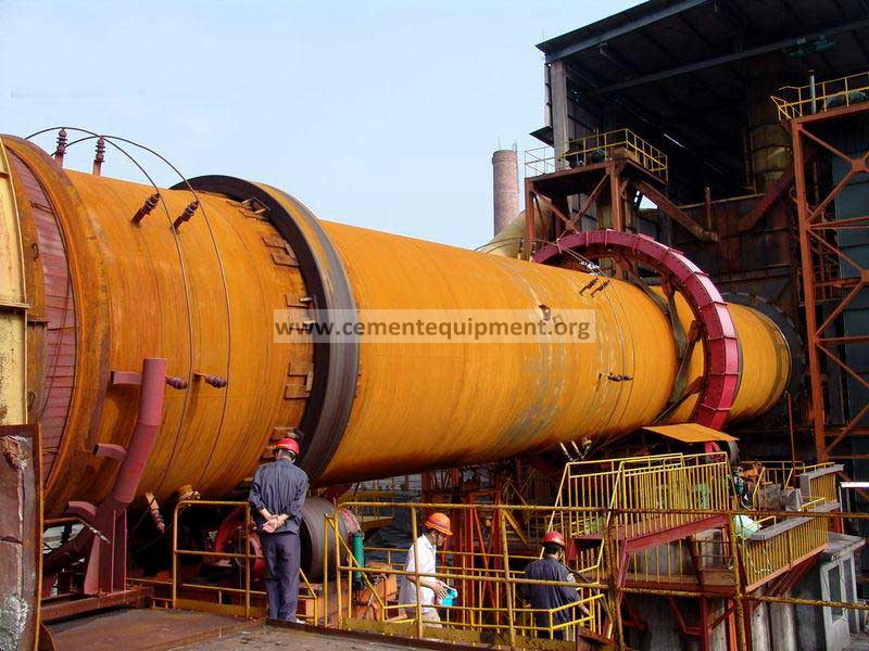
A rotary-kiln speed signal dropout must be separated from a real drive-speed change before control settings are touched. Compare encoder speed with motor/VFD frequency and another independent speed indication, inspect the encoder coupling or target, verify power and signal continuity, then check PLC scaling and input diagnostics. Do not bypass a speed signal that participates in kiln drive protection or process interlocks.
Restore a stable kiln-speed measurement when the displayed rpm freezes, drops to zero, jumps or disagrees with the actual drive condition.
Use encoder feedback, motor/VFD speed, drive current, local rotation evidence, sensor supply, pulse signal, cable condition and PLC input diagnostics together.
Separate genuine speed variation from encoder mechanics, electrical signal loss and PLC/scaling faults before recalibrating or changing drive controls.
Fast diagnostic order
- Confirm whether kiln mechanical speed actually changed when the signal dropped.
- Compare encoder feedback with VFD/motor speed and drive current.
- Inspect encoder mounting, coupling, target or pulse wheel for movement and damage.
- Verify encoder supply, output signal, cable continuity and PLC input diagnostics.
- After correction, compare the signal through startup, steady speed and a controlled speed change.
Capture the signal failure before resetting
Record: kiln speed command; encoder feedback; VFD frequency; motor current; main-drive status; auxiliary-drive status; PLC input quality; timestamp of the dropout; recent electrical work; encoder/alignment work; and whether the signal failed continuously or intermittently.
If the encoder drops to zero while VFD frequency, motor current and observed kiln movement remain steady, focus on the measurement chain. If all speed evidence changes together, investigate the drive system first.
1. Prove the kiln did or did not change speed
Use an independent indication that is permitted by the site procedure: VFD speed estimate, motor encoder, secondary tachometer or other approved reference. A real speed change can come from drive trips, torque limits, motor control issues or mechanical loading. Do not classify the event as an instrumentation fault until actual rotation is credible.
2. Inspect the encoder mechanical connection
Where the encoder is shaft-coupled, check coupling integrity, keys, setscrews, alignment and support rigidity. A loose coupling can slip intermittently while appearing normal at rest. Where the encoder reads a toothed wheel, magnet or target, inspect target condition, runout, spacing and contamination.
3. Check sensor mounting and environment
Inspect the bracket for vibration movement, heat exposure and dust ingress. Cable strain at the encoder can create intermittent faults as the structure moves. Confirm the installed sensor remains within its manufacturer-specified environment and mounting arrangement.
4. Verify supply and output signal
Measure the encoder supply at the device and verify the pulse or analog output according to the sensor type. Compare the signal locally and at the PLC or drive input. A good local signal with a bad control-system value points toward field cable, junction boxes, terminals or the input channel.
5. Inspect cable and shielding/grounding
Check for damaged cable, loose screens, poor terminations, routing near high-power conductors and moisture in junction boxes. Intermittent noise can create spikes or missing pulses. Follow the installed encoder and control-system grounding practice rather than adding ad-hoc ground connections.
6. Check PLC scaling and diagnostics
Review raw input, engineering-unit scaling, pulse frequency conversion, quality bits and fault diagnostics. If the raw count remains healthy but displayed rpm is wrong, the problem may be logic or scaling rather than field hardware. Compare current parameters with the approved configuration.
7. Verify through the operating range
After repair, compare encoder feedback with the independent speed reference during startup, steady operation and a controlled speed change. The ratio should remain repeatable and the signal should not freeze or drop during vibration and thermal stabilization.
Kiln speed-signal diagnostic matrix
| Observed pattern | Likely direction | Priority check |
|---|---|---|
| Encoder reads zero; VFD and kiln rotation steady | Measurement-chain fault | Coupling/target, supply, pulse signal, wiring |
| Signal jumps with structural vibration | Loose mount / intermittent cable | Bracket, connector, cable strain, target gap |
| Local signal good; PLC speed bad | Input/scaling issue | Field cable, input channel, raw count, scaling |
| All speed indications fall together | Real drive-speed event | Drive status, torque/current, VFD, mechanical load |
| Error appears only after warm-up | Thermal movement / heat-related fault | Encoder environment, bracket movement, cable/connector |
Common mistakes
- Changing kiln-speed calibration before checking the raw encoder signal.
- Replacing the encoder without inspecting a loose coupling or target.
- Ignoring cable movement and vibration-related intermittent faults.
- Assuming a VFD speed estimate proves the encoder circuit is healthy.
- Bypassing speed feedback that is part of a protection or interlock function.
Return-to-service acceptance checklist
- Encoder feedback agrees consistently with the independent speed reference.
- No dropout, freeze or spike occurs through startup and normal steady operation.
- Mechanical coupling/target and sensor mounting remain secure.
- Supply and signal remain stable at the field device and control-system input.
- PLC scaling and diagnostics are correct and documented.
- No forced value or temporary bypass remains active.
- The final speed comparison is recorded as the new baseline.
Frequently asked troubleshooting questions
Can the kiln keep rotating while the encoder reads zero?
Yes. If the encoder coupling, target, supply or signal circuit fails, the kiln can continue mechanically while the measured speed disappears.
How do you separate encoder failure from a real speed change?
Compare the encoder with an independent approved speed reference, VFD/motor behavior and drive current. Consistent mechanical speed with lost feedback points toward the measurement chain.
Why does the speed signal fail only when the kiln is hot?
Thermal movement, heat exposure, connector expansion or bracket movement can change alignment or electrical integrity. Inspect the installation under the conditions where the fault occurs.
Related Infinity technical guides
Engineering reference basis
Use the installed kiln-drive, encoder, VFD and PLC/OEM documentation for final coupling alignment, supply limits, pulse scaling, speed tolerances and interlock requirements. The workflow above separates genuine drive-speed events from measurement-chain faults before adjustment.