Contents
Cement Manufacturing Process
by TIZITA MOGES , SELAMU ABULE & DEREJE ENDALAMAW
IF YOU NEED THIS GUIDE AND ALL OTHER USEFUL EXCEL SHEETS WHICH WILL MAKE YOU MASTER THE PRODUCTION , PROCESS , MAINTENANCE ACTIVITY IN YOUR CEMENT PLANT KINDLY CLICK HERE

Raw Material Preparation and Raw Meal Design
Part One: Raw Material Preparation
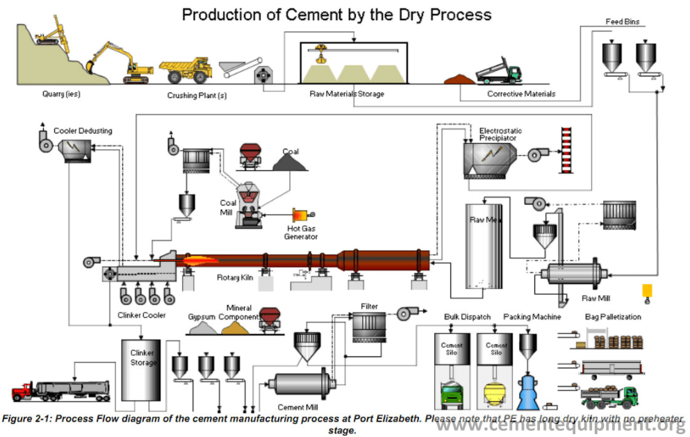
The production of cement is started from quarrying the raw material. The main raw materials are limestone, basalt, sand stone, pumice, gypsum. Site Exploration of suitable deposits, for the raw material has three main aims:-
- Verifying the quality of the raw materials.
- Establishing the range of variation in quality of the raw materials throughout the working life of the deposit.
- Verifying the workable reserves of raw materials.
Quarrying is the breaking of the rock in a safe and economical way and then transporting the result to a plant for further reduction in size.
Two main aspects are to be considered for raw material investigation:
- Geometry of the raw material deposit, that means geological boundaries like interfaces of formations, faults and also topography.
- Quality of the rocks in terms of chemical and mineralogical composition, physical characteristics like hardness, abrasiveness, pozzolanic activity etc…
Quarrying of raw materials involves (Process of Raw Material Extracting)
- Mining and removal of Overburden
- Drilling and Blasting
- Loading
- Haulage
- Crushing
- Site restoration
It is a process of excavating and exploiting the raw materials underground for any use. Limestone for example, the key raw material can be mined in the quarries with compressed air drilling and subsequently blasting with explosives. The mined limestone is then transported through dumpers or ropeways to the plant.
The method of removals and machinery usages are depend on the under listed factors relating to the overburden material nature. For example rock over burden can be broken by blasting or ripping, machineries such as back acting/dragline excavator; bulldozer can be used for the overburden removal. Moreover, ground surface which is intact has better bearing capacity than ground in which its top has been removed.
- Strength and hardness; soil or solid rock
- Thickness of the layer
- Haulage distance
- Load bearing capacity
- Susceptibility to weathering (lack of ability to resist)
Drilling and Blasting are the favored combination for breaking out the raw material. Blast holes are drilled using drilling machines according to the desired length, diameter, spacing, and geometric features. The typical Drill depth and Diameters are:
Drill depth: max. 25m
Drill diameter: 80-165mm
Blasting is the most widely used method to excavate limestone for cement production as the rock is usually too hard to be ripped or dozed. After blast holes are drilled, they will be charged with explosive and the charges are fired. The amounts of explosive to be used depend on the specific explosive consumption. The specific explosive consumption can be determined from reduced scale blasting measurements based initially on known values from
practical experiences under comparable conditions. The specific explosive consumption depends on the nature of the rock which may be hard, soft or compact.
Loading machines in the present technology is concentrated towards hydraulic excavators and wheel loaders. The machines used for loading in open-pit quarrying for solid rock such as excavators, hydraulic excavators, wheel loaders and others depending on the nature of the quarry.
Haulage comprises the transport of the fragmented rock pile material from the loading point to the crushing plant. The choice of haulage system may be
- By rail mounted vehicles
- By rubber-tired vehicles and other means such as belt conveyors, wheel loaders etc.
The rock pile loaded to the loading machine is either fed to a primary crusher in the quarry, the product of which is further transferred to the cement works, or to heavy dump trucks to be transported to a crushing plant away from the quarry. This depends on the particle size of the material.
The choice of haulage method depends primarily on considerations of economy. In addition local factors such as haulage distance and gradient, number of working points in the quarry, bearing capacity of the ground, and the need for selective quarrying.
Crusher is a device that is designed to reduce large solid chunks of raw material into smaller chunks. Crusher will be erected near to the limestone quarry. The limestone and sandstone is transported from their respected quarry through the help of dump trucks to the crusher, which is directly passes the crushed raw material to the ropeway so that the size is reduced to 25 mm. The crushed limestone is stored in the stockpile through stacker.
There is a lot of crusher used in cement industry such as;
- Impact crusher
- Hammer crusher
- Jaw crusher
- Gyratory and cone crusher
- Mobile crusher
But, Debra cement factory uses only the first two (Impact crusher and Hammer crusher).The raw material is crushed at quarry by primary crusher (impact crushers) Grain size (75-90mm).
Hammer Crushers: –
In DMC, these are mainly used for crushing of correctives, pumice, coal and clinker. They are used for size reduction of hard to medium grain size and sometimes for wet and sticky material. Hammer mills work with reduction ratios as high as 1:40 to 1:60 as primary and 15:1 as secondary crushers. It can be installed for single stage crushing, primary crushing or secondary crushing. Types of hammer crushers used in DMC, double shaft hammer crushers and work with the impact effect of the hammers. The material crushed in double rotor hammer crushers is limited to certain characteristics of its properties.
Impact Crushers: –
These crushers are suitable for non-abrasive, from soft to hard, slightly wet materials. The predominant stress used is impact; however cut and attrition are also used. The maximum reduction ratios are 40:1. There are two types; single rotor impact and double rotor impact crushers. The specific power consumption of this crusher is 0.7 – 0.9 Kwh per ton of material. The size reduction work of impact crushers is limited to certain quality characteristics of the crusher feed.
Table 1: crusher type in DMC and their capacity
| Crusher type | Capacity (tph) | Output grain size | Power consumption (KWhpt) |
| Impact crusher for limestone sand stone and gypsum | 1000 | 90%<75mm 97%<90mm | 1.8 (excluding cross country belt) |
| Hammer crusher for additives and correctives | 400 | 90%<25-50mm | 0.9 |
| Hammer crusher for coal | 150 | 90%<75mm | 0.7 |
Environmental considerations demand the landscape of a quarry site to be restored after any quarrying operation ceased on the site. The restoration involves restoring the landscape to something like its original or to an environmentally friendly way and re-cultivation of the surrounding to create a biologically and ecologically intact natural habitat.
In Debra cement factory, the quarry site is 7kmaway from the plant site, which incurs high transport cost to the factory. Hence, the raw materials (limestone, sandstone and gypsum…) are needed to be transported by cross country conveyer belt which has a transportation capacity of 1000 ton/hr.
Belt conveyors are- used for transport of solid objects and bulk materials at great speed, covering distance from crusher to cement mills (up to 6.4km). Belt Conveyor is also a suitable means of transporting raw materials and other bulk materials in large quantities within a short space of time.
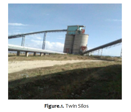
Among the major raw materials required for cement production, limestone, sandstone, and gypsum are abundantly available in Debra. As it was observed from the preliminary geological survey of the raw materials study, [this study was conducted by company during its establishment], that the deposit of the above materials is much more than enough for the whole plant life for 5,000tpd clinker production capacity. After the required raw materials are transported to the plant site, limestone and sandstone are stored in temporary storage called vertical silo or twin silo.
Twin silos are used to store limestone and sandstone that are transported by belt.
Limestone capacity- 2,000tons
Sandstone capacity- 1,000tons
Further, from vertical silo limestone is stored in large storage called circular yard which has a capacity to store 50,000 ton
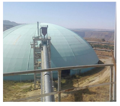
Figure.2. DMC lime stone storage (circular yard)
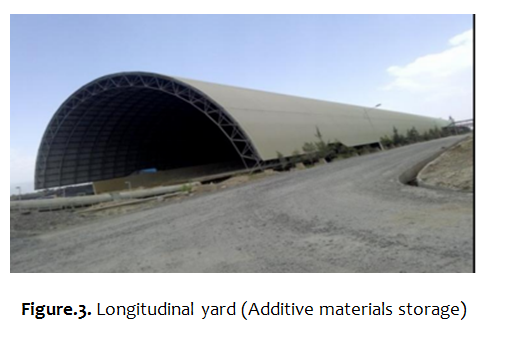
Besides, Additive materials like sandstone, basalt, pumice and gypsum is stored in longitudinal yard which has a capacity to store 48,000 ton. However, gypsum is directly transport to longitudinal yard. In addition to this, Coal, is also another useful raw material used as energy source, it is transported from South Africa and stored in a storage which has had a capacity similar to that of limestone.
Capacities of each materials store in longitudinal yard are;
Sandstone………6,000tons
Basalt……………12,000tons
Pumice…………..24,000tons
Gypsum…………..6,000tons
Moreover, the above stated raw materials, Basalt (contain clay and Fe2O3), is extracted very near the plant site and transported by track so that it is crushed by hammer crusher at production site and then by using conveyor belt it is allowed to enter in to longitudinal yard for storage.
The principal raw materials for cement manufacturing are:
- Limestone
- Silica and alumina from basalt , shale or sand
- Iron from iron ore or steel mill scale.
- Sand stone
- Pumice (volcanic ash for Portland Pozzolana cement )
- Gypsum
General Properties of Raw Material Sources
The basic raw material of the cement production is limestone. Limestone consist of predominately of calcium carbonate (CaCO3), in generally its most stable modification known as calcite, in addition, they often contain magnesium, aluminum and iron combined as carbonates and silicates; Silica (SiO2), usually in the form quartz, is also often present. It is critical that limestone (CaCO3) is of adequate quality to permit proper raw feed formulation. The presence of excessive Mg contamination in limestone often leads to inferior clinker that forms potentially less durable cements. Mining of limestone requires the use of drilling and blasting techniques. The raw materials are loaded at the blasting face into trucks for transportation to the crushing department.
Provide ingredients such as SiO2, Al2O3, Fe2O3, and alkalis that take part in the formation of the essential phases – silicates, aluminates, and the melts in cement clinker.
Properties of pumice include: – It increases the quantity of cement and decreases the strength and the cost of the cement. . Since, pumice, the raw material, required for production of PPC cement, is not available in Derba. This material has to be transported by trucks from Meki. In addition to this, pumice is a light material less dense than the other ingredients.
Gypsum one of the raw materials which are added in the clinker and also some part of Gypsum is inter-ground with the other raw materials in the raw materials preparation. The addition of Gypsum is good for the settling time of the cement
Specifically enriched in one of the four main elements (bauxite, iron ore, sand, high-grade limestone, etc.). Correctives are used in small quantities only to adjust the chemical composition of the raw mix to the required quality targets. If an essential chemical component needed in the cement raw mixture is not present in the required amount, corrective ingredients are used as additives.
Physical Properties of Raw Material
Moisture content: One of the physical properties of raw materials for cement production is determinations of its moisture contain. The moisture content of raw materials is a very important consideration as it varies between wide limits in the same materials owing to such factors as condition of shipping and storage and the chemical and physical nature of the materials. Water may occur in materials in two different ways as water mechanically held (mechanical water), or as water of constitution. Water of constitution is water tied up as an integral part of the molecule, as in (Al2O3.3H2O) or as water of crystallization as in borax (Na2B4O7.10H2O). This water of constitution is generally constant for any one particular material. The mechanically held water is the water or moisture on the surface or between the particles of the material. To determine the water mechanically held or, in some cases, some of the water of crystallization, a weighed sample is placed in a dryer at 110◦C until it comes to constant weight. The difference between the weight of the sample when dry and its original weight is the weight of the mechanical water contained in it. The percentage moisture may be based either on the original weight or on the dry weight. The latter is the better practice.
Moreover, drying oven is used to remove the free water (moisture) in a raw material like Lime stone, Pumice, and Sand stone except Gypsum at 105 ◦C for one hour.
- Gypsum: can be dehydrated very easily at 45 ◦C to remove moisture.
The energy amount and cycle-time that needed for drying and processing the raw materials are proportional to the moisture contents. For example more energy is needed to produce enough hot air in order to dry the raw materials with high moisture. Therefore the moisture content affects and controls the productivity and performance of the raw milling process,
Generally, the moisture content of raw materials for cement production are usually prescribed by different specification is not to greater than 1 %.
Grading size (Sieve distribution): the other physical property of the raw material is its grain size. Which matters the mechanism how to transport from the quarry and the type of Crusher used to grind it.
Portland cement is made up of four main compounds: tri-calcium silicate (3CaO ・SiO2), dicalcium silicate (2CaO ・ SiO2), tri-calcium aluminates (3CaO ・ Al2O3), and tetra-calcium aluminoferrite (4CaO ・ Al2O3Fe2O3). The percentage compositions of these compounds vary according to the type of cement required. Small amounts of uncombined lime and magnesia also are present, along with alkalis and minor amounts of other elements. Trace amounts of hexavalent chromium are very often present in the final product. Portland cement dusts less than 1% crystalline silica.
The elemental compositions of the basic raw materials used by DMC are labeled below
- Sand (sio2)
- Limestone(caco3)
- Basalt(clay and shale) provides Al2 o3, Fe2o3 and sio2
- DMC consume *Limestone (89-91%)
* Basalt (8%)
*Sand (1%). But, vary with its proportion
Each raw material has a variety of chemical and mineralogical compositions. The product quality and processing times are extremely variable and depends on the compositions. The main purpose of the raw materials quality control is in order to accelerate the sintering reactions and decrease the needed energy to burn the raw meal. The material quality control process can be achieved by adding corrective materials such as: Corrective limestone (pure lime stone) and Sand stone.
It is Blending of raw components on (integrated) pre-blending stock piles to a given target composition.
Process’s variables and factors
Process of mixing the raw materials is required to obtain specific physical and chemical properties. Blending and homogenization process defined as: a creating of required specific physical and chemical properties of raw materials by mixing and integrating certain quantities of those materials.
Number of problems can occur and arise within the cement production line as a result of materials compositions variations. For example
- Corrosion problems: corrosion within this process has classified into two groups. First, cold corrosion which can be occurred because of oxidation state. The cold corrosion is resulted from the reaction of the equipment surface with water and oxygen. Secondly, chemical corrosion which can be occurred as a result of the chemical reaction between the corrosive gases and equipment. The raw materials and fuel are counted as the major sources of the corrosive gases such as: sulphur oxides (SOx), calcium chloride (CaCl2), and nitrogen oxides (NOx).Corrosion situation affects the performance of raw milling system by increasing the breakdown rates and reducing the equipment availability and reliability.
- Build-up formation of materials and rings forming: Sulphur, Chlorine, and alkali components may accumulate at the cold zone of the kiln obstructing the raw meal flow leading to unstable operation. Number of factors can control and keep values of these volatile components at minimum levels such as: chemical properties of raw meal and fuels, Oxygen rates, and flame characteristics.
Homogenization of raw materials is carried out in pre-blending stores. With proper layout, all storages for raw materials can be operated as blending storages with varying efficiency. Raw materials typically are stored in piles representing three to seven days production, and raw meal is stored in silos that hold three to four days production. There are various layouts of raw material storages for pre-blending.
There are a number of ways to stack limestone. Most common are the chevron or windrow methods, in which the materials are stacked in many layers in the longitudinal direction of the raw material pile. The material is reclaimed from the entire cross section of the pile and the number of reclaimed layers in the cross section is the important parameter for the blending efficiency.
The pre-homogenizing systems have two major operations: 1) storing or stacking and 2) retrieval or reclaiming of materials. That is why the facilities are also often known as “stacker-re-claimer systems,” Depending on their homogenizing capability, two broad categories can be considered for these systems.
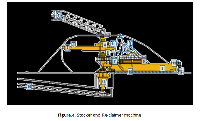
Stacker and Reclaimed machinery
Stacker –It receives crushed limestone from income belt conveyor. It consists of a movable carriage which moves along the proposed stock piles. Stacker belt goes over this movable carriage and drops material. It rotates on its axis about 1200 .Stacker capacity to feed material in the circular storage is 550 tons/hr. Besides, stacker is a large machine used in bulk material handling. Its function is to pile bulk material such as limestone, Sand stone, Pumice, Coal and Gypsum on to a stockpile. There are two types of stackers, circular and longitudinal.
Reclaimer- Reclaimer consists of a hoe or a rake which dislodges material in layers in small
thicknesses from the entire cross section of the pile. Dislodged material falls on a belt to take it to hoppers of mills. Recamier capacity to feed materials on the belt is 1,250tons/hr. In addition to this, a re-claimer also is a large machine used in bulk material handling applications.
A limestone stockpile (closed stock pile) has been proposed at the plant site with stacker and re-claimer. The re-claimer will help in feeding a homogenized limestone by mixing rich quality LS with low grade mineral. By installing a re-claimer in the plant, the plant can achieve not only the quality raw material input but also the conservation of natural resources by utilizing low-grade raw material. The crushed limestone is sent to the stacker and re-claimer, which will improve the pre-blending in the ratio of by these means it, prepares the materials to the conveyer transported in to the proportion unit.
Reclaiming takes place at the opposite end of the pile to that beings tacked. A bridge re-claimer works, to and fro, across the cross-section of the pile parallel with a radius line. The sweeping movements of the raking harrow mounted on the re-claimer cause limestone to
slide to the base of the pile. The chain system of there-claimer then drags the material into a hopper beneath the central column of the stacker-reclaimer. Homogenized limestone leaves from the central hopper on an underground conveyor.
Moreover, in Longitudinal yard there is Pumice (SiO2; Al2o3); Gypsum (caso4); Basalt (SiO2; Al2o3, caso4) and Sandstone (caco3).
- Pumice; is alight material(less dense than other ingredients like basalt), which is extracted and transported from Eastern Shoa around Meki. It is used 25-30% (30% in PPC and 5% in OPC).
- Gypsum; is pure limestone, is about 95% of caco3. It is used to for setting time or to correct hydration rate.
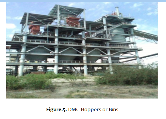
After the raw materials are leaving from longitudinal and circular yards, they enter into the hoppers or bins through belt conveyor. They are used for feeding crushers and mills. There are four in numbers, three of the hoppers holds different raw materials like Limestone (capacity of the hopper to hold 800 ton); Sandstone (capacity of the hopper to hold 200 ton); and Basalt (capacity of the hopper to hold 200 ton). And the fourth one i.e., high grade limestone or correcting material of the hopper has a capacity to hold up to 200 tons.
Percent’s of raw materials required
Limestone…… 65%
Sandstone…….5-10%
As well, for the corresponding hoppers, there existed a weigh feeder to proportionate the raw materials prior to joining in to vertical raw meal for grinding.
Weigh feeders:
Weigh feeder is a machine which allows the raw material to the required quantity from the hopper and sent it to the required area.
Parts of weigh feeder
- Apron feeder: which used for limestone feeder.
- Endless belt: which used for sandstone, basalt and corrective weigh feeder.
- Vibrator motor: which used for material dropping on the endless belt
- Pulse jet bag filter
Transporting Crushed Raw Material to Raw Mill
This stage continues after the crushed lime stone is stocked pile. A belt conveyor collects the raw material from the stock pile with the help of hoppers below the stock pile. So these belts are fixed under the stock pile to collect the raw material.
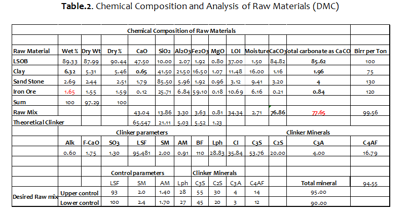
The purpose of calculating the composition of the compound in the raw mix is to determine the quantitative proportions of the raw component in order to give the desired chemical and mineralogical composition of the clinker. The basis for calculation is the chemical composition of the raw materials. By using the parameter like lime saturation factory [LSF),
Silica modulus (SM), Alumina modulus(AM) etc. of desired clinker it would be possible to calculate the proportion of the different raw materials in raw mix .The raw mix design comprises raw mix proportioning standard specifications of the cement types to be produced.
Raw material Proportion Station:
Raw material proportion station is the place where the raw materials like limestone, sand stone and basalt are mixing together.
Corrective lime stone, sand stone and basalt are transported turn by turn to their respective storage in silo. Now the proportioning process is done with the help of varying speed belt conveyors. The amount of each material received by the raw mill feeding of the belt conveyers depends on the speed of the belt conveyors which taken the materials from their respective storage. A proper raw mix design is based on the given raw material situation on the process design and on environmental consideration and also used for a good product quality and smooth kiln operation.
The proportioning of raw mixes for ordinary Portland cement and Pozzolana Portland cement are mostly based on the following specific criteria.
- Lime Saturation Factory LSF
- Silica Modulus SM
- Alumina Modulus AM
Is the amount of CaO which is enough saturated or combine SiO2, Al2O and Fe2O3 to form Portland cement clinker
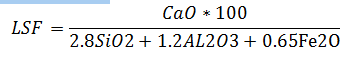
- In order to produce good clinker the LSF is usually kept between 92 6%.If the LSF is above 99% the raw mix CaO Become harder to burn, higher fuel consumption, excess CaO in the clinker.
- Desired value 92-98 %
If LSF below 92% the clinker is so easy to burn the refractory brick may be washed out, infiltrate with coating rings. Free lime content is usually low…Form less porous & bally clinker ….. Results, hard to grind, Excess of liquid phase in the burning Zone, there is a tendency to ring formation and coating washing, The potential C3S is lowered and the C2S is increased proportionally……Reduce early strength of cement
In general high LSF has following effect
- Fuel consumption increases
- Burning zone temperature increase and heat loss by radiation increases.
- Presence of free CaO affects the quality of clinker and produce unsound cement.
- Clinker burning hard with high fuel consumption.
- Free lime content is low and the high the early strength of the cement.
- Difficult to combine with other oxide (hard to burn)….. a tendency to high free lime
It’s the ratio sum of Fe2O3 and Al2O3 in the kiln blend; it characterizes the ratio of solid to liquid in the clinker. So that the right amounts of the aluminates C3A and Ferrite C4AF are obtained in the clinker. The major effect of silica ratio is one the quantity of flux or liquid phase potentially present at clinkering temperature.
The silica ratio falls between 2.0-2.4. At the clinkering temperature the silica is for the most part contained in the solid phases Tri-calcium and Di-calcium silicate which absorb only small amounts of alumina and iron oxide in solid solution.
- more difficult the raw mix to burn due to lower content of Al2O3 and Fe2O3
- Clinker is hard to grind
- Low cement strength
- Difficult to combine with CaO …hard to burn
- More fuel consumption
- High heat loss by radiation
- Reduces the amount of coating in the burning zone
- Produces dusty clinker
- Easy burning for the raw mix
- Liquid phase high Al2O3 and Fe2O3
- Kiln unstable and slow hardening cement
- Excessive coating formation (ring formation)
- Fast brick infiltration with clinker melt
- Snowman formation in cooler
- Resulting bally clinker which is hard to grind and its strengths are lowered
The Alumina modulus establishes the relation between alumina and iron to determine the viscosity of liquid phase
AR= Al2O3/Fe2O3
Desired value 1.4 – 1.60
As the alumina and the iron oxide are almost completely melted at clinkering temperature, the iron modulus characterizes the composition of the melt.
When AM high: Viscous slag, hard burning, high early cement strength with low sulfate resistance
Effect of high Alumina Modulus
- The more viscous flux at a given temperatures
- Decrease sintering rate due to decrease in reactant contact (decreases the kinetic energy of the reactants)
- Increase sintering temperature to make less viscous ( to increase sintering rate)
- High fuel consumption to increase sintering temperature
- High C3A formation
- High heat of hydration (Reaction of C3A with water releases 900KCal energy per mole of C3A)…… Results concrete thermal expansion
- Tendency to high early strength due to high heat of hydration , consequently it absorbs high amount of water for quenching
When AM low:-Fluid slag, easier burning and Low early cement strength with high sulfate resistance and low heat of hydration.
- Means high Fe2O3 content (less viscous clinker melt )
- Hard to grind due to formation of less porous clinker
- Form Dark in color of clinker
The proportioned raw material is feed first to a grinding mill. In the mill, particles ground in to very fine sizes. In the grinding unit, drying, grinding and mixing takes place simultaneously. Hot gas from clinker burning unit is passed into the grinding unit to assist the drying and grinding process. The mill exerts mechanical action on the feed particles and grinding takes place. The mechanical action in the mill also homogenizes the raw material in the mill.
Mill separators use the gas from the mill and mechanical force to separate fine particles from the coarse particles. A fine particle output from the separator is transported to cyclone through a fan. The mill output usually contains some coarse particles and the coarser ones have to be separated before storage. The coarse output returns to the mill for regrinding by bucket elevator. Gas leaving the mill is drawn out by a fan called waste. The gas exiting the cyclone still contains fine materials and goes to gas cleaning unit, which can be bag filter. At cyclone, some dusts and gases are sucked by fan so that they can be sent to bag filter to be de-dusted.
Separation as performed by mechanical air separator is division of a given materials in stream into two separate stream using air as carrying media. One stream contains only fines particles and the other contains coarse particles. The fine raw meal which is settled in the cyclone is conveyed to air slide via screw conveyor. The air slide fed the meal to bucket elevator then to homogenizing silo.
The majority of mechanical air separator generates the circulating air inside the separator itself. Materials leaving the distribution plate are based on three forces. These are:
- Centrifugal force ; Fc
- Force of ascending air current force ; Fd
- Force of gravity Fg.
Working principle
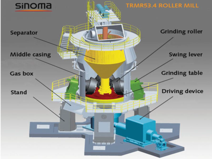
Raw mills uses pressure and shear generated between the rollers and rotating table to crush and grind limestone, basalt and sandstone. The rotation of grinding table accelerates the materials toward grinding track and passes it under the roller. The ground material is supplied on to rotating grinding table connected to bevel spur gearbox which is driven by an electric motor or hydraulic drive.
- VRM Capacity to grind-420ton/hr.
- feed material limestone, sandstone and basalt
- Power of motor-4.8mw
- Separation-air separator.
Hydraulic tensioning occurs when grinding roller with grinding table rotating during operation. In hydraulic gas accumulator, nitrogen gas accumulator is used as a shock absorber during operation.
The vertical roller mill fulfills four main functions in one compact piece of equipment:
- Grinding
- Drying
- Separation
- Transportation
The process is called a drying /grinding process, where most of the material/product is transported pneumatically by drying gases.
- Grinding: the material is ground between rollers and grinding table while passing from the center of the table to the nozzle ring. The commnation method belongs to the most efficient grinding processes applied in the cement manufacturing.
- Separation: the ground and dried material is lifted up with the drying gases. In the separator, the too coarse particles (tailings) are rejected to the grinding table. The fines leave the mill and are conveyed to dust collector.
- Drying: the process air consists mostly of waste gas from a kiln or cooler or is supplied by a hot gas generator. Drying occurs during transport through the grinding and separating process stage.
- Transport: the drying gasses are utilizing to serve as conveying media. The first transport stage is the internal circulation and the second is the separator. At last, the product is extracted from the separator and pneumatically conveyed to cyclones or a filter where the product is collected and fed to a silo. The clean gases are exhausted to the ambient and/ or re-circulated to the mill.
De dusting system is used to prevent the dust from escaping into the environment, most of the cement plant machinery and equipment is working under negative pressure, which requires the ventilation and cleaning of large volume of air gases respectively.
- Mechanical collectors, i.e. cyclone separator
The use of cyclones strictly speaking is not warranted as pre collectors before bag filters because both of them are capable of handling full load of dust content. But cyclones help in emergencies to bypass the dust collector. By using gas tight dampers, it would be Possible to attend to the maintenance and repairs of the dust collector without requiring stopping the plant.
Air Slide
Air slide pneumatic conveying equipment used to convey dry and powder material. In DMC it is used to convey fine material and cement powder. It is used to convey fine materials from
Cyclone to homogenization silos by small induced draft (ID) fan under it.
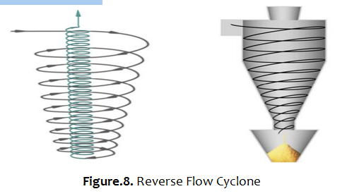
De-dusting system using Cyclone relies on the action of the centrifugal forces on the dust particles carried along in the swirling stream of gas. The particles are thus flung radically outwards to the wall of the cyclone from where they fall into dust hopper. All cyclones work by centrifugal force. Two main factors affect cyclone efficiency. These are:-
Velocity particle moves towards the wall or collection area of the cyclone where it is theoretically collected and length of time available for collection: Residence Time. Moreover, the two main metrics describe cyclone performance are Pressure drop and Fractional efficiency curve (FEC). Most of the early cyclones were used to collect dust created from mills that processed grains and wood products. In the decades that have followed, however, cyclones have found application in virtually every industry where there
is a need to remove particles from a gas stream. Figure below shows cyclones Basic Flow Patterns (Reverse Flow Cyclone)
The bag filters are important equipment in cement factory. In these filters current flow that includes gas and dust cross through the pores are located in the stuff filter and filtrate by remaining on the bag. Afterward, by dust increase on the bag, the filter is shaken until dust collecting leads to exist hopper. This system in the project is called mechanical method. They are used extensively in cement works for cleaning the exhaust air from tube mills, crushers, material handling installations, silos and bins, dispatch loading plants. Since an accumulation of dust on the pores of the fiber occur, cleaning of the filter media is necessary. Bag house (Bag Filter) is an air pollution control device that removes particulates released from cyclone by using induced draft fan.
Parts of bag house
Housing or shell Material dropped from bag house and air conditioning tower is transport by
Drag chain to homogenization silo.
- Solenoid valve
- Connection hopper
- Filter cleaning device
- Fan
The dust collected in bag house and GCT is transported via drag chain then fed to the air slide.
Conditioning towers in the cement industry are used for cooling exhaust gases from the kiln before they are conveyed to the bag house. Inlet temperature from pre-heater to Gas Conditioning tower is 600 degree Celsius and outlet is 250 degree Celsius. This temperature is used to drying material in vertical raw mill.
The hot exhaust gases enter the top section of the vertical, cylindrically-shaped and insulated tower for cooling by water injection. The gases are drawn through the conditioning tower by a fan.
Besides, additional object of the Gas Conditioning Tower is to condition and cool kiln gas before it is de-dusted in bag house. The cooling of the gas protects the bag from high temperatures and the higher humidity of the gas increases the performance of the bag house. Furthermore, some of the dust in the kiln gas is separated from the gas by gravity in the Gas Conditioning Tower.
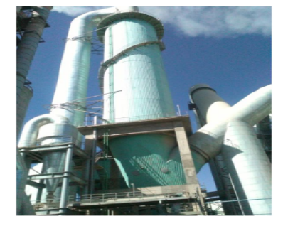
Figure.10. Gas Conditioning Towers
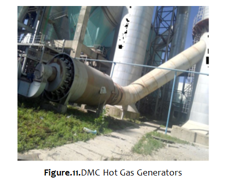
Hot gas generators: are suitable for drying process and used in conjunction with grinding
Plants when there is insufficient hot gas from conditioning tower. In this process air is heated under high pressure.
Homogenizing silo (Raw meal silo)
This is an area where the raw meal is stored temporarily. It has two roles: blending and storing
Here Blending is an act of mixing or homogenizing of raw meal using compressed air to get uniform chemical composition and meal fineness.
In Cement Industry raw meal blending or homogenization is always done in silos. It is the last homogenizing step in the line of the raw mix preparation processes installed with the aim to reduce the residual (relatively short-term, high frequent) compositional variations observed for the raw meal produced in the raw mill.
The basic principle of blending process is one or combination of the following mechanisms
- Distribution of input raw meal at the top of blending silo
- Pneumatic dry blending by aeration of raw meal with the aeration units placed at the bottom of silo
- Segmental aeration with difference in the pressure of air supplied for aeration of various segments for mixing of raw mix
Insufficient control of the raw mixture and its blending will cause large variations in the chemical composition of the kiln feed (fluctuations in product quality)
If the kiln is operated at a constant material residence time and temperature, such variations regarding chemical composition and physical characteristics also will cause variations in clinker composition like free lime.
When unintended variation in kiln feed composition (the raw meal reclaimed from such silos will then be fed to the kilns without further homogenizing) causes large variation in free lime, operators may make incorrect changes to kiln operation, assuming changes are needed when they are not.
The operator may be obliged to increase the burning zone temperature to achieve the desired free lime level; by keeping the kiln on the hot side, the maximum clinker free lime is brought to the average value. Which results reduced brick life time, increased NOx emission, production of dusty clinker, unstable kiln operation etc.
The fuel penalty for burning to an average of 0.8% free lime because of large variability instead of an average of 1% can easily be on the order of 4% (high fuel consumption). When the kiln is operated on the hot side, alkalis and sulfate become more volatile. This, in turn, might increase the possibility for build-ups in the preheater and Kiln inlet (increased tendency to ring and build up formation).
Hard burning tends to cause low clinker porosity, large crystals of alite, and often contributes to generation of dust instead of good nodular clinker. Slows down the cooling process because of high temperature and low-porous clinker, it is more difficult to cool. Reduced clinker porosity can make the clinker harder to grind, increasing finish mill power consumption or reducing mill production as well as reduce cement strength. This is used as a prerequisite for achieving steady process conditions for the kiln.
Besides final compositional homogenizing and blending, homogenizing silos serve as intermediate stores (in DMC case the silo can store 24,000 t)separating the two continuous processes raw grinding and clinker burning which are not necessarily operated at similar rates.
Compositional uniformity and blending factor
The simplest and most common statistical measure is the Average or Mean.
Blending factor is the ratio of standard deviation of input raw meal to standard deviation of output raw meal. The standard deviation is a measure of how widely values are dispersed from the average value (the mean).
For calculation of blending factor of a silo, input and output raw meal samples are to be collected in regular intervals and to be tested for example CaCO3 content having a standard deviation of 0.3% ( in DMC case).
Given a set of N measurements, X1, X2………… XN the mean value X is given by
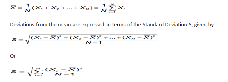
The difference between each measurement Xi and the mean value X are squared so that positive and negative fluctuations above and below the mean do not cancel each other.
The square root of the sum of the squared variations is then divided by the number of measurements N to obtain an average measure of variation, having the same units as the measured quantity.
The natural and induced blending which occurs at a particular homogenizing stage may be expressed by a Blending Factor BF defined as the ratio of the incoming and discharge
Standard Deviations:
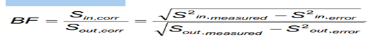
The Standard Deviation needs correction for sampling and analyzing error for which the silo can’t be blamed. For determining the sampling and analyzing error double sampling method is proposed.
Easy burning raw mixes tolerate fluctuations in a wider range than difficult burning raw mixes. Nevertheless it is useful to have some guide values regarding tolerable compositional fluctuations at hand.
In Cement Industry it is generally accepted that no further improvement of raw meal quality can be expected by additional blending/homogenization for the kiln feed variations given in below table.
Table 3; standard deviation of raw meal
| Characteristic | Analytical error excluded (standard deviation) | Analytical error included (standard deviation) | |
| CaCO3 | % | ≤0.2 | ≤0.25 |
| CaCO3 max. | % | ≤0.3 | ≤0.35 |
| CaO | % | ≤0.11 | ≤0.15 |
| CaO max | % | ≤0.17 | ≤0.2 |
| SiO2 | % | ≤0.1 | ≤0.15 |
| Al2O3 | % | ≤0.07 | ≤0.04 |
| Fe2O3 | % | ≤0.04 | ≤0.04 |
| LSF | % | ≤1.0 | ≤1.5 |
| SR | % | ≤0.04 | ≤0.06 |
| AR | % | ≤0.06 | ≤0.08 |
There are various types blending silos having blending factor from 6:1 to 15:1. The more the blending factor, the blending is the more effective.
Silo concepts for raw meal homogenizing
The silo concepts used in raw meal homogenizing can be classified according to the kind of the working principle applied into the following categories:
- Fluidized homogenizing systems (Batch type- two storey arrangement and continuous-over flow type)
- Continuous blending silos (Aerated gravity system)
- Multi pack silo
With this system raw meal in a large capacity silo is completely fluidized by the admission of compressed air through suitable inlet in the bottom of the silo. It has high efficiency but it consumes high energy and it needs a high construction cost (needs at least two to four silos).
Continuous blending silos
Development of the continuous silo concept started with the introduction of raw material preblending systems in the cement process out of the need to reduce power consumption for cement raw meal homogenization. The increasing efficiency of such blending systems went along with a gradual reduction of the size of blending silos.
Process Concept
Continuous blending silos aim at raw meal homogenizing and intermediate storage in one common silo. The system follows the concept of a blender. For that purpose the raw meal is fed into the top of silo in horizontal layers. Horizontal layering of the raw meal is achieved while feeding the silo via a spider-type air slide system. When reclaiming meal from the silo a funnel will form on top of the discharge point at the product surface. The declining funnel surface cause blending of particles originating from different layers when sliding down the slope to into the transport channel.
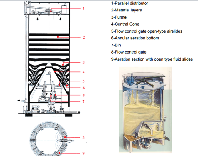
Figure.12. Continuous blending silos
Cement raw meal activation for discharge is achieved by slight aeration. For that purpose compressed air is introduced through a permeable media covering the silo bottom. The silo bottom itself is divided into (seven in DMC) segmented areas, the number of which is a function of the silo diameter.
Aeration air is supplied at a low rate and a low pressure into the selected aeration sector for raw meal activation. This air leaves the silo together with the activated raw meal in air slide; it will not penetrate into the raw meal column on top of the activated sector. Aeration is switched systematically by means of a special valve sector by sector.
The Inverted cone the inverted cone silo represents the pure concept of the aerated gravity silo. The silo is, as said by its name, equipped with a huge inverted cone covering most of its center bottom area.
The remaining annulus is divided into segmented areas that are covered by open air slides. Each sector is equipped with its own outlet. Raw meal is activated predominantly at the silo’s circumference by sequential air supply to the individual sectors, avoiding by this the formation of huge zones of stagnant product and then each air slide supplies the meal to one common bin at the bottom. The meal is discharged at bottom of the bin to air slide then to bucket elevator finally fed to preheater.
- Blending effect: max. 5:1
Evaluation of the continuous blending silo concept
- Applicable for wide capacity ranges
- Low energy consumption
- Low investment cost
Disadvantages
- Limited raw meal homogenizing compared to the fluidized homogenizing silos
- Insufficient reduction of long-term, peak or step-type fluctuations
Design Data (in DMC case)
Size of silo: 74mx22.5ǿ
Investment cost……………………………….……50-60%
Capacity to store……………………………….….24,000t
Air rate per net aeration area……………….1 – 1.5m3/min m2
Air pressure………………………………..…….. 0.6 to 0.8 bar
Power consumption…………………….….…..0.8KWh/t
Standard deviation of CaCo3 …………….…..max 0.3% at silo out
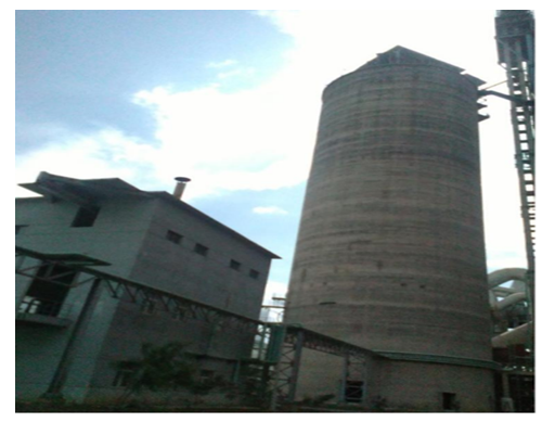
Figure.13. Homogenizing silo
The efficiency of a homogenizing/blending silo system is mainly impaired by;
- Insufficient working condition of the silo system
- Insufficient operation of the silo system
- Insufficient raw mix composition control
Limits in blending efficiency
- The case of insufficient reduction of a peak disturbance
The blending efficiency of a continuous blending silo is commonly given by the ratio of the silo inlet and outlet Standard Deviations for the selected compositional characteristic:
Unfortunately the efficiency factor do not means that all compositional peaks fed into the silo are reduced by the same factor. The compositional fluctuations of different kind are reduced with different efficiencies.
EXAMPLE Homogenizing / blending effect of raw meal silos for LSF
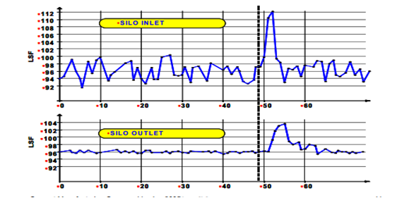
Figure.14. Homogenizing / blending effect of raw meal silos
Silo operation
All fluctuations with a periodical time shorter than about 5hr are reduced with efficiency better than 5:1. The first part in the diagram (Fig. above) represents efficient reduction of such short-time fluctuations.
Long-term fluctuations with periodical times exceeding 5hr are not reduced sufficiently. A compositional oscillation for example with a periodical time of 20 h is reduced with a low efficiency of just 1.16:1. In this case the silo has no chance to achieve a sufficient blending result. The only way to improve the situation is to cut any long-term fluctuations by frequent adjustment of raw mix composition, i.e. by frequent adjustment of the weigh feeder set points. Continuous blending silos are not in a position to reduce the peak disturbances sufficiently.
The only efficient measure to compensate for such peak disturbances is by creation of a defined counter-peak by making adequate adjustments to the raw mix composition.
Table 4, some of the problem their remedies in homogenizing silo
| Problem | Remedies |
| 1. Lump formation due to water ingress into the silo | -Empty and clean the silo completely -Check silo roof and wall with regard to leaks, seal the leaks and coat the silo wall |
| 2. Non-uniform distribution of raw meal in continuous blending silos | -Install a guide plate in distributor box -check installation (level) of distributor box |
| 3. Raw meal lumps obstruct material flow from the silo | -clean outlet boxes and install a lump breaker -install dryer for the aeration air |
| 4. Reduced air supply to the aeration system | -check air aspiration filter on permeability and clean the filter -check air distribution system on permeability and clean the system -check pressure distribution in air distribution system |
| 5.Continuous blow-off of blower safety valve | -relief blower safety valve by a reduction of its differential pressure -Measure volume of excess air, reduce air rate by this volume by a proportional reduction of the blower speed |
| 6. loss of aeration air | -check external air distribution systems with regard to leaks -empty and clean the silo completely as to check the aeration system on leaks |
| 7.Specific aeration air rate (m3/m2min) should be constant and not function of the silo diameter | -check opening of manual valves |
| 8.Faulty operation of air distribution valves resulting more than one activated sector at a time | -check operation of air distribution valve |
PYROPROCESSING
It is a process of heating of the raw meal to the required temperature so as to produce the desired clinker compounds in an economic way at higher productivity in the preheater and kiln. Or it is a process to convert natural mineral to hydraulic mixture using high temperature.
In order to obtain clinker from a properly proportioned, grinded and homogenized raw meal, it must be treated with heat obtained from burning fuels. The main processes and chemical reactions that take place during clinker formation are:-
- Evaporation of free water
- Evolution of combined water in the argillaceous (containing clay) components
- Calcinations of the calcium carbonate (CaCO3) to calcium oxide (CaO)
- Reaction of CaO with silica to form dicalcium silicate
- Reaction of CaO with the aluminum and iron-bearing constituents to form the liquid phase
- Formation of the clinker nodules
- Evaporation of volatile constituents (e. g., sodium, potassium, chlorides, and sulfates)
- Reaction of CaO with dicalcium silicate to form tricalcium silicate
- Cooling of clinker
These reactions are combinations of endothermic and exothermic reactions.
The Pyroprocessing unit consists of:
- Preheating and calcining unit
- Rotary kiln
- Cooler
- Fuel Handling and Firing
PREHEATER
Preheaters are cyclones are arranged vertically, in series, and are supported by a structure known as the preheater tower. It can be considered as a heat transfer tower supports a series of vertical cyclone chambers through which the raw material passes on the way to the kiln. To save energy modern cement plants preheat the raw material before they enter the kiln. Rising more than hundred meter, hot exit gases from the kiln heat the raw meal as they swirl down the cyclone string.
Advantages of the preheater system
- It can raise the yield of the kiln significantly
- It can ease the kiln burning zone of thermal load, as a result of prolonging the service life of the lining and raising the running rate.
- It is advantageous to stability of burning schedule
- It is easy to burn the inferior coal with low heat loss per clink
- For raw material and fuel containing high alkali, chlorine and sulphurs, its orientation ability is strong.
- It exhausts lower content of NOx in the waste gas, and the pollution of the environment is comparably small.
- Benefit the technique reform of the old kiln, cover small area, need low equipment expenses and the yield can become to duplication.
All modern cement kilns are equipped with suspension preheaters. Preheater system is composed of Cyclone, Duct, Chute, Calciner and Kiln inlet hood etc.
Stages
Cyclone preheater kilns can have any number of stages between one and six, with increasing fuel efficiency with more cyclone preheater stages. The feed to the kiln is delivered to the top stage of the preheater and passes down through the successive stages of the preheater to the precalciner and rotary kiln.
The more preheater stages the lower will be the thermal energy consumption of the kiln as more of the heat from the kiln exhaust gases is recovered. Preheater exit gas temperature will reduce by ~30°C for each additional preheater stage, from ~360°C for a 4-stage preheater, to ~330°C for a 5-stage preheater. Todays, five stage preheaters represent the economical and optimum between investment cost (structure height, foundation), pressure drop and heat Consumption to ~300°C for a six stage preheater. But now in Japan and china seven stages preheater is under operation. However, civil costs and pressure drop across the preheater tower rise with each additional preheater stage. Gas temperatures should always be higher than material temperatures in any preheater stage as the material is heated by the gas.
Note: Numbering of stages is always from top to bottom: top stage = stage 1.
When the number of preheater stages was decided the important considerations will have been the
- Raw material moisture (i.e. drying heat requirement)
- Cost of thermal energy
- Cost of electrical energy
- Gas handling system (temperature limit)
- Soil conditions (foundations, earthquake zone -> height of structure or tower)
- Capital cost required to build the tower
The higher the moisture content of the raw materials the more heat is required in the preheater exhaust gases to dry the raw materials in the raw mill. If the raw materials have ~8% moisture then 4 preheater stages is the maximum that can be installed for the preheater exhaust to be able to dry the raw materials in the raw mill. With ~5% moisture then 5 preheater stages can be installed. With ~2% moisture then 6 preheater stages can be installed, etc. In DMC, the modern and efficient 5 stage preheater is under operation. The drawbacks of higher gas exit temperature after the bottom cyclone and the preheater higher pressure drop can be compensated by five preheater stages and modern low pressure drop cyclones.
Number of strings
In DMC case, the Preheater system is composed of a double-string preheater and in-line Calciner. Fuel and preheated raw material entered the Calciner are taken by high-speed current of air, suspend inside in the stove, go upside in spiral flow and fire and resolve at the same time in both string. The combustion of the fuel gives out heat and the raw material absorbs heat to decomposition. These two processes happen very quickly at the same time in suspended situation.
The number of strings of cyclones is generally related to the plant’s capacity requirements – the more capacity needed, the more strings typically needed. Most commonly, the system encompasses one or two strings, but more may be considered for the largest of plants. A transition from one to two strings relates to the size of the cyclones and the resulting volume of the preheater construction.
Cyclone
The key component of the gas-suspension preheater is the cyclone. A cyclone is a conical vessel into which a dust-bearing gas-stream is passed tangentially. This produces a vortex within the vessel. The gas leaves the vessel through a co-axial “vortex-finder”.
Each stage of the preheater consists of a gas riser duct and a collection cyclone. The raw meal is led in to the riser duct of the first stage cyclone and the intake has a spreader box for distribution of the raw meal in the gas stream. The exhaust gas is drawn out of the rotary kiln and up through the gas riser ducts of the preheater. The rising gas lifts the feed up through the gas riser ducts and into the collection cyclones where the swirl created by the geometry of the cyclone and the central dip tube separates the feed from the gas. Gas exits the cyclone up the preheater through the dip tube, while the cyclone passes the feed down the preheater to the next stage.
Visualizing the gas flow path in the preheater demonstrates the resistance to drawing the gases from the kiln created by every cyclone stage of the preheater which causes pressure drop.
Equipment manufacturers have been successful in reducing the pressure drop across preheater cyclones from ~20 mbar to ~7mbar by changes in cyclone geometry and increasing the cross sectional area of the inlets and dip tubes exiting the cyclones.
Dimensioning of a cyclone preheater is a careful consideration of;
- Separation efficiency
- Pressure drop
- Part load operation capability
- Size of the preheater
- Cost of the project
Cyclones pressure drop reduction is achieved by
- larger inlet and outlet area
- less gas velocity and more space for gas flow
- more length of central pipe
- first stage is designed for high degree of separation by keeping more length of cylindrical portion of cyclone
Size of cyclones
The selection of cyclone sizes is a balance of having the smallest cyclone dimensions while maintaining the lowest overall pressure drop through the preheater. This is to minimize the induced draft (ID) fan power consumption – the most power consuming part of a kiln system.
The size of cyclones relates to the maintaining of desired gas velocity criteria and efficiency. Increasing the preheater cyclone dimensions reduces the pressure drop. But for any given cyclone geometry, stable preheater operation (without raw meal falling through the riser ducts) requires a certain minimum gas velocity.
Typical size of cyclone in DMC;
Cyclone C1 with 4-ǿ5.0m
C2 -3 with 2 -ǿ7.4m
C4-5 with 2-ǿ7.6m
Cyclone efficiency
The collection efficiency of the cyclones is also dependent on the velocity of the gases entering and exiting the cyclone, and the swirl induced by cyclone geometry. The cyclones do not have 100% collection efficiency. Some of the feed entering the cyclone is not collected and passes out of the cyclone, up the preheater tower with the exhaust gas.
The cyclones in the middle of the tower may have collection efficiencies of 85% or lower meaning that there is a considerable recirculating load of material in the preheater. Low efficiency of the bottom stage cyclone means that calcined material can migrate up the tower. That material can recarbonate liberating energy and elevating the preheater exit temperature and the losses of thermal energy in the exhaust gases.
The top stage cyclones (tall cylindrical portion-slim cyclone) are designed to have higher collection efficiency of 93~97%. Any feed not collected by the top stage cyclones exits the preheater as dust and must be collected in the exhaust gas cleaning equipment like bag house.
If there is only a small difference in temperatures between successive preheater stages it is an indication that the collection efficiency of the lower cyclone has deteriorated and too much preheated meal is migrating up the preheater with the exhaust gas. Again inspection and refurbishment of the dip tube and internal fittings at the next overhaul is the likely solution.
Other than having the correct design parameters, cyclone should be equipped with
- Dip Tubes (also called ‘immersion tubes’, ‘thimbles’ or ‘vortex finders’)
- Meal flaps
- Splash boxes (or splash plates)
Dip Tube (Immersion Tube, Vortex Finder, Thimble)
Central pipes (thimbles) are standard in all cyclone stages to provide high separation efficiency and for optimum pressure drop. It makes the gas to follow a 180 to 360° rotation thus creating the desired centrifugal force for the separation effect.
Splash Box
It is designed for optimum meal distribution across the gas duct cross section. The principle is based on impact on a plate.
Meal Flap
Is designed to prevent gas from by passing up through the material pipes between the cyclone stages, the pipes are equipped with sluice flaps (tipping valves) designed for full opening. Good meal distribution in the cyclone riser ducts is ensured by adjustable spreader plates in the distribution boxes.
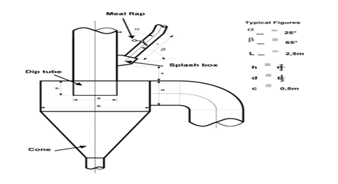
Figure.15. cyclone design
Air cannon
Air Cannons are pneumatic, bulk material moving systems that quickly release compressed air into a storage vessel to restore flow to material that is
- clinging
- bridging
- rat-holing
- arching
Compressors are also used for air blaster in preheater system to clean blockages due to collections of material in cyclones and ducts.
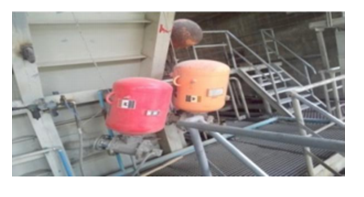
Figure.16. Air cannon
Cyclone Shapes
The separation efficiency of a cyclone gets better with longer dip tube and increasing
distance between swirl (cylinder) and dust collecting cone, i.e. with high and slim shapes.
The top stage of preheaters is designed for high separation efficiency.
Induced draft fan
It is used to suck hot gas from cooler, kiln, precalciner and each cyclone then drive away it to gas conditioning tower. If more heat is required in the preheater exhaust for drying the raw materials in the raw mill then the kiln operator must increase the exhaust gas temperature by reducing the feed to the kiln while maintaining the induced draft (ID) fan speed and the fuel supply to the kiln. The preheater exit temperature is controlled by minimizing the speed of the ID fan preventing too much heat loss.
The speed of the ID fan must also be adjusted to ensure that sufficient combustion air is drawn into the kiln and precalciner from the cooler. The velocity (10-15 m/s) of the gases must be sufficient to lift the feed up the gas risers and into the cyclones – if not the feed will short-circuit preheater stages with major adverse impact on kiln stability and thermal efficiency. The kiln operator must adjust the ID fan speed to have a small excess of oxygen in the preheater exhaust gases. Whether that excess oxygen should be 2% or 4% will depend on the kiln feed system and the condition of the preheater and kiln seals. Where there is air in leak at the kiln inlet seal and the preheater stages then the preheater exit oxygen content will inevitably rise. ID fan consume 2500KW power (in DMC).
The kiln operator should always be monitoring the temperatures and pressures in the preheater and the excess oxygen in preheater exhaust gases. The preheater exhaust gas oxygen content and temperature will be the parameters that the kiln operator is trying to control to target to maintain the thermal energy efficiency of the kiln. These will be controlled by the speed of the ID fan.
Pressure drop
It has been found that the total pressure drop of one cyclone stage is caused by about 1/3 by the gas duct (i.e. lifting of the meal) and 2/3 by the cyclone geometry. Both the swirling of the gases and the changes of direction caused by the cyclones lead to pressure drop across the cyclones.
Six preheater stages causes maximum pressure drop as compared to lower stages since the pressure drop across the preheater tower increases with each additional preheater stage. The higher the pressure drop across the preheater the larger must be the preheater ID fan and the more electricity will that fan consume. This is why six preheater stages is the maximum which needs high cost to install.
Any increase in the pressure drop across a preheater stage is an indication of a restriction in the gas flow through that stage. Some minor components of the kiln feed will melt and evaporate in the burning zone of the cement kiln. The minor components which behave in this way are chlorides, sulphates and salts of the alkali metals. After evaporating in the burning zone they are carried back to the preheater in the exhaust gases where they re-condense on the feed and are again carried back into the kiln. This causes them to concentrate in the kiln in a so-called “alkali cycle”. Some of the alkalis also condense on the walls of the ducts in the preheater, causing the feed to stick to the walls and creating build-up which restricts the gas flow through the preheater. The kiln operator will monitor the build-up of material in the preheater by the pressure profile across the preheater. The control of this build-up is via the combustion conditions and the temperature control in the rotary kiln.
Operating Problems of Suspension Preheaters
Some reasons for poor preheater performance frequently experienced:
- Worn out or non-existing immersion tubes (often in bottom stage)
- Open inspection doors, leaky gaskets or holes in the pre-heater (cold false air leaks in, can be detected by hissing sound)
- Blocked or non-existing meal flaps
- No splash boxes (especially older preheaters)
- Excessive dust circulation due to poor separation efficiency of cyclones
Circulation problem
Cyclone preheaters are sensitive to circulation phenomena. Cyclone blockages cause kiln
stops resulting in production loss and dangerous cleaning actions.
Possible causes are:
- Excessive input via feed or fuel (Cl, S, Na, K)
- Chemical unbalance (sulphur, alkali ratio)
- Unfavorable kiln/burner operation
- Unfavorable design geometry of bottom stage and kiln gas riser duct area
Counter measures known today allow to solve the problems are:
- Change feed composition or fuel quality
- Improve burning conditions
- Install automatic cleaning (air cannon or big blasters) at critical locations
- Change temperature profile by installing a small secondary burner
- Install a kiln gas bypass system(usually not recommended due to heat and material loss unless severe condition happened)
Main technical parameter of Preheater System (in DMC case):
Capacity (t/d)…………………………………………………………………….…….5600-6000
system resistance (Pa) ………………………………………………………..4500-5000
Decomposition rate before entering kiln (%)………………………..…..>90
Exhaust gas temperature getting out of the first cyclone (℃)….…≤340
Cyclone stages ……………………………………………….…………………………….5(double-string)
Type of calciner…………………………………………………………………….………in-line (ǿ7.8m)
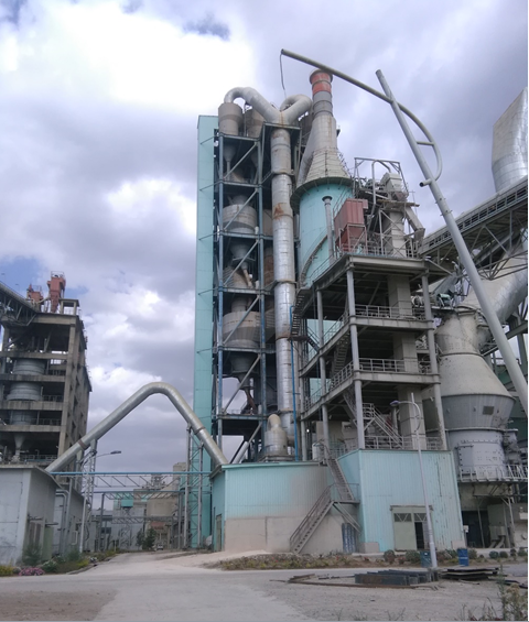
Figure.17. The five stage double string preheater
PRECALCINING SYSTEMS
Additional thermal efficiencies and productivity gains have been achieved by diverting some fuel (60-65%) to a calciner vessel at the base of the preheater tower. This system is called the preheater- precalciner process. Problem was encountered with the long-wet and suspension preheater kilns that were used at the time at which providing all the thermal energy requirements of the cement clinkering process through the main burner of the rotary kiln progressively increased the thermal load on the burning zone as the capacities rose.
Production capacity is a function of the volume of the rotary section of the cement kiln. As capacities of long kilns and preheater kilns raised the length and diameter of the rotary sections of the kiln increased. With all the fuel fired at the front of the kiln and thermal load on the refractories at the front of the kiln increased linearly with the production capacity. Thermal load is a function of the amount of thermal energy input per hour and the cross-sectional area of the kiln. Kiln linings with sufficient refractoriness to withstand the burning zone thermal loads involved were and are not available. The solution to this problem was delivered by precalcination technology.
In the conversion of kiln feed into clinker the evaporation of any residual water, dehydration of clay minerals, calcination of limestone (CaCO3) and clinker flux formation are all energy consuming reactions. Calcination of the CaCO3 is the most energy consuming of these reactions. The solution to the burning zone thermal load problem with high capacity kilns was to direct the thermal energy input to the point in the kiln where this reaction is taking place, rather than inputting all the thermal energy through the main burner. A precalcination furnace was added at the base of the preheater at which 65% of fuel fired.
Calciner vessel (In Line Calciner) is built into the kiln riser pipe
- Through the calciner, the kiln exit gas as well as the tertiary air from eta cooler passes through
- Degree of calcination is around 90 – 95% as the temperature is in the range of 870 – 900°C 9
- Gas velocity is in the range of 5-7m/sec and retention time is around 4-8 seconds
- Secondary air is around 900-1100°C and Tertiary air around 750 -900°C
The main advantages of precalcination are:
- More stable kiln operation due to better kiln control via two separate fuel feed/control
points - More stable kiln operation due to controlled meal conditions at kiln inlet
- Reduced thermal load of burning zone
- Higher kiln availability
- Longer life of burning zone refractories
- Larger capacity with given kiln dimensions; smaller kiln for given capacity
- Possibility of increasing capacity of existing kilns
- More favorable conditions regarding circulating element problems
- Allows shorter kilns (L/D<16 with 3 supports)
- Lower NOx emissions
There are three basic precalciner arrangements available from several suppliers:
- In-line (installed in the kiln exhaust gas flow- precalciner as enlarged kiln riser duct)
- Offline(installed off the kiln exhaust gas flow)
- Separate line(off-line calciner with a separate preheater string)
In-line calciner
Precalciner arrangement with the gas riser duct from the kiln inlet to the lower stage cyclone was simply lengthened and a gooseneck introduced or a Precalcining chamber was introduced within that riser duct. In this configuration all the gases exiting the rotary section of the kiln pass through the precalciner, hence the designation as an in-line precalciner. The feed from the second lower most cyclone of the preheater is directed to the precalciner and carried to the lower most cyclones where the calcined material is collected and passed to the inlet of the rotary section of the kiln.
Advantages are:
- The simplicity of the arrangement
- The in-line drafting of the preheater, precalciner and rotary section of the kiln meaning
that only one preheater and induced draft fan is required - That with all the kiln exit gases passing through the precalciner, staged combustion can be used to reduce NOx emissions from the kiln
Disadvantages of the in-line precalciner configuration
- Precalciner firing takes place in the presence of the vitiated exhaust gas from the
kiln and the suspended feed to the kiln. Oxygen content of the gas in the precalciner is therefore depleted and the combustion of the fuel is retarded. Poor mixing of the kiln exhaust gas and tertiary air can exacerbate the problem of poor combustion of the fuel resulting from local deficiency of oxygen. - Small residence time in the precalciner at ~900°C may be sufficient to achieve >90% calcination of the feed, but is not necessarily sufficient to achieve 100% burn-out of the fuel.
- Not achieving 100% burn-out of the fuel in the precalciner can lead to
combustion continuing in the lowermost cyclone and be evidenced by meal
temperatures higher than gas temperatures and “sparkling” of the hot meal when
a sample is brought into the atmosphere. Lowermost cyclone gas exit temperature rises and with it the temperatures up the preheater to the exit and
therefore the thermal energy losses from the kiln and energy consumption.
The latest development of precalciner technology was aimed at
- Completes combustion of fuels even for low reactive fuel
- Suitability for a wide range of fuels
- Low emissions of NOx
Calcining of Raw Meal in calciner
Calcination of the CaCO3 is the most energy consuming of reactions. During the process of heating up a raw meal, the Calcining does not happen suddenly at a well-defined temperature, but starts at about 600 – 700°C and ends between 900°C and 1,000°C. CaCO3 dissociation takes place from ~600°C but only at higher temperatures does the speed of calcination become significant. When the temperature of the kiln feed powder is raised to ~900°C this calcination reaction is completed within ~10 seconds. In kilns equipped only with suspension preheaters ~30% of the calcination takes place in the preheater with the rest taking place in the back section of the rotary kiln but with precalciner >90% is completed. Among all reactions taking place when burning clinker, the Calcining – also called Decarbonisation – requires the highest amount of energy; the dissociation of carbonates, primarily calcium carbonate according to the reaction
CaCO3 + heat → CaO + CO2
Not only the temperature, but also the retention time of the raw meal is an important parameter of Calcining. Heat transfer from gas to suspended raw meal in a preheater stage is achieved in a fraction of a second; the complete calcination at a temperature of about 900°C in suspension requires a reaction time of 3.3 – 8 seconds. However, as only 90 to 95% of the Calcining should take place in the precalciner in order to avoid clogging problems, a residence time of about 3 to 4 seconds has proven to be sufficient. To perform both above mentioned tasks, i.e. to keep raw meal in suspension for a few seconds at 850 to 900°C in a stationary vessel without clogging, is the common process target of all PC systems.
It is not desirable to achieve complete calcination in a preheater as melt formation
may then begin leading to clogging and blockages in the preheater. Fuels are fired in the Precalcining furnace to provide the thermal energy to complete the energy consuming calcination reaction. Typically 60~65% of the total fuel input to the kiln is directed to that Precalcining furnace.
To overcome burning zone from cooling due to high excess air present in main burner flame, separately ducting of combustion air from the cooler to the Precalcining furnace via a tertiary air duct is crucial.
Decomposition rate of limestone is increased by
- Increase in temperature of raw meal
- Lowering CO2 partial pressure in combustion gases
- Lowering dust load of combustion gases
- Lowering particle size of raw meal
- Decreasing crystal content of CaCO3
- Silicic acid formed by decomposition of clay minerals
Heating Rate and Dissociation Speed of limestone
- Low Heating Rate (100 °K/min): Dissociation Speed depends on transport phenomena gas-heat flow to and gas transport from the inner of the limestone particles.
- High particle size and Heating Rate (250 °K/min): Dissociation Speed hindered by low heat conductivity and high CO2 partial pressure.
- High Heating Rate (450 °K/min): Increased reactivity of CaO with SiO2 (from 800 to 1000°C). No recrystallization and defects in crystal lattice.
- Kiln speed: lower rpm produce higher Heating Rate.
- Alkalis (up to2%) increase Dissociation Speed by lowering activation energy for limestone.
Combustion in Precalciner
The combustion in the precalciner takes place under quite different conditions compared to the main firing because:
- The temperature of the combustion environment is in the order of 850 to 900°C (flame temperature of the main firing: around 2000°C).
- PC systems (in-line systems) use an air-gas mixture for combustion (main firing: pure primary and secondary air) while others use pure air (off-line and separate line systems).
- In all PC systems preheated raw meal is suspended in the combustion air or air-gas mixture in order to absorb the heat released there by maintaining the temperature at a comparatively low level. By all means must Sintering of material avoided, as this would lead to clogging in the precalciner stage.
On the account of the less favorable combustion conditions complete combustion is not always readily obtained, it requires a certain experience to achieve optimum performance. Precalciner use M.A.S burner (in DMC case) which is delivered at two different positions of calciner circumference.
Of the various parameters influencing the combustion performance, the following are perhaps the more important ones:
- Good mixing of the fuel with the available oxygen (This is particularly difficult to achieve with in-line calciner). Optimum fuel dispersion into the gas flow (liquid fuel-atomization) is essential.
- Retention time for combustion has to be sufficient. The combustion must be completed in the PC stage. Otherwise, it will continue in the next stage (post-combustion) where the temperature level is lower and therefore less favorable for the calcination. This results in not optimum utilization of the heat which leads eventually to higher fuel consumption.
- The flow pattern of the air/gas mixture (resp. tertiary air) has to be favorable for the combustion.
- The meal distribution in the combustion zone has to be optimum, i.e. causing minimum distortion of the combustion (CaCO3 as well as CO2 can also react with C – carbon from the fuel – to produce CO!).
Basic arrangements of precalcining systems
Air separate-AS (use tertiary air which is extracted from the kiln hood or from the cooler roof and drawn via a separate tertiary air duct parallel to the kiln to the precalciner)
Air through-AT Systems (used only combustion air which is drawn through the kiln)
Tertiary air duct damper
To balance the combustion air flow between the kiln and calciner, a tertiary air duct damper is provided for reliable regulation of the tertiary air gases. The damper design features a solid refractory blade for long, reliable life.
The rotary kiln relies on the calcination degree of the feed entering the kiln being consistent. Any variation in the calcination degree varies the thermal work that must be completed in the rotary section of the kiln and leads to disturbances in the kiln operation. For the precalciner to deliver that consistently calcined material to the rotary kiln it relies on a consistent flow of preheated meal, fuel and tertiary air into the precalciner.
Any interruption of flow of preheated feed into the precalciner will cause a spike in the precalciner temperature. Fuel supply must be cut to control the precalciner temperature but the fuel delivery must be restored as soon as the feed flow into the precalciner is restored. Interruptions in the flow of preheated feed into the precalciner can be caused by “stickiness” of
the feed due to the alkali cycle.
It must also be remembered that the calcination of the calcium carbonate in the precalciner is an endothermic reaction, absorbing the thermal energy input to the precalciner. The temperature therefore remains steady while this thermal energy is being absorbed. Degree of calcination of the feed does not vary with the temperature in the precalciner but with the amount of thermal energy input to the precalciner. The PID loop therefore does not really achieve its primary objective of providing consistently calcined feed to the rotary section of the kiln. To do that the amount of fuel fired in the precalciner must be linked to the amount of feed to the kiln.
Limitations and Restrictions
Even though the advantages of precalciner systems are doubtlessly convincing, not all types can be used in all cases. Limitations are:
- Additional installation (fuel dosing, calciner, tertiary air duct) as well as the relatively
smaller rotary kiln sets a lower economical limit to PC systems for new plants at around
1200 t/d. - Alternative fuels containing hazardous components can only be used in the main firing
due to the high temperature level there. The potential to use such fuels is then lower for
PC kilns. - Higher exhaust gas temperature and higher pressure drop can be a drawback in specific cases.
- Separate line calciners for new installations are only feasible if a two-string arrangement is required for the capacity.
ROTARY KILN
The rotary kiln is a long steel cylinder, slightly inclined furnaces, lined with refractory to protect the steel shell (due to its extremely high temperature) and supported by steel tires and rollers. It rotates along its longitudinal axis, driven by a pinion and gear system. It is also a type of high temperature oven used for clinker burning process. The raw material mix enters the kiln at the elevated end but the combustion fuels introduced into the lower end of the kiln.
The materials are continuously and slowly moved to the lower end due to the inclination and rotation of the kiln. The raw materials are changed to cementitious or hydraulic minerals as a result of the increasing temperature within the kiln.
It has ubiquitous fixtures of chemical process that involves different chemical reactions and it can handle feed stocks with broad particle size distributions or whose physical properties change significantly during processing, while the long residence time of the material within the kiln promotes uniform product quality.
TYPES OF KILN
- Wet process kilns (usually long kiln)
- Grate preheater kilns
- Cyclone preheater rotary kiln
- Preheater- Precalciner kilns
Kiln can be vertical, horizontal, long or short
In modern kiln system the introduction of a Precalcining furnace at the base of the preheaters a further >90% of the calcination was taken out of the rotary section of the kiln.
From a process perspective the taking of the drying and preheating processes out of the rotary section of the kiln and then most of the Calcining out of the rotary section has had important implications.
A long kiln with all these processes taking place with the single, long rotary tube; the
rotational speed of the kiln had to be matched to the slowest processes (1rpm or less) of the drying and preheating. It was very important to tie the rotational speed of the kiln to the feed rate in order that an even load of material is maintained throughout the kiln length.
Once the drying and preheating were taken out the rotary section of the kiln this tie between feed rate and rotational speed became less important.
With the introduction of a Precalcining furnace and taking virtually all the calcination out of the rotary section of the kiln the link between feed rate and rotational speed became even less important. In fact there are advantages to bringing the CaO liberated by the calcination of the CaCO3 into the sintering zone as quickly as possible to prevent it from stabilizing and becoming “dead-burnt”. A high rotational speed of 3.5 rpm or more became advantageous in order to
combine the CaO with the SiO2, Al2O3 and Fe2O3 as quickly as possible. On many precalciner kilns it has proved to be a mistake to slow the kiln down in response to any cooling in the burning zone as this allows stabilizing of the CaO and makes subsequent combination into the clinker more difficult.
DMC use the modern preheater – precalciner kiln with the following features
- Kiln clinker output …………………………………≥5000tpd
- Kiln size………………………………………………….Diameter= 5.2m; length=78m
- Pyro process heat consumption………………≤735 Kcal/kg.cl (coal)
≤745 Kcal/Kg.cl (HFO)
- Power consumption……………………………….30KWh/t
- Slope(inclination)…………………………………..40
Process related to kiln zones
- Calcining zone
- Heating zone
- Liquid zone burning zone
- Sintering zone
- Cooling zone
Calcining zone
Calcination is decarbonation of carbonates in the raw meal into free CaO and liberating CO2. Due to highly endothermic reaction, the material temperature is around 9000c
Partial pressure of CO2 below the surface is high enough to generate “rushes’’ of uncalcined raw meal with a high, unsatisfied heat requirement. Rush of uncalcined raw meal causes sudden cooling of the kiln burning zone. Considerable formation of C2S raises the temperature as soon as all the CO2 has been expelled.
Heating zone
This zone encompass from calcining zone up to the liquid zone. It is located behind the flame where the bed of the kiln charge has dark color.
Reaction among Lime, Alumina, silica and Iron are takes place to form temporary intermediate products. As there is no heat consumption in this zone, the temperature raises rapidly. Temperature reaches 13000 C at the end of the heating zone. In this zone formation of a hard and dense coating as well as liquid phases begins.
Liquid zone
Its temperature is 1300 to 1350 0 c. Nodulisation of clinker starts here but its content mainly depends on the raw mix composition.
Size of nodules depends on
- the quantity and properties of the liquid phase
- size distribution of the solid particles in the feed
- residence time of the material in liquid phase
Nodulisation starts by capillary bonding succeeded by crystal bonding while the fluid material is the binding agent. Length of this zone depends on the temperature profile and its composition of raw mix. Formation of C3S starts but slow.
High temperature/sintering zone
It is directly under the illuminated part of the flame. Formation and growing of C3S particles and the sintering of the solid phases is done in this zone. The most viscous kiln charge exists and its temperature is between 1400 and 14500C.
Formation of C3S is faster where the material is nodulised and not agglomerated. Improved and more frequent contact is achieved between lime rich particles and silica rich particles.
Cooling zone
Material starts to solidify and agglomeration occurs due to cooling. If the cooling is slower, C3S decomposes to back to C2S and free CaO. Free CaO reacts with unstable C-A minerals to form C3A. Grindability of clinker is improved in rapid cooling. Rapid cooling is achieved by locating the sintering zone near the discharge end. In rapid cooling, clinker exit temperature is high followed by a sudden cooling at the first compartment of cooler.
The major operational parameters usually considered are:-
- Material residence time
- Kiln degree of fill
- Kiln slope
- Kiln Capacity
- Burnability
Burnability
Burnability expresses the difficulty for the material to be converted at any time, in the process temperature. Insufficient mix control or blending will result in larger variations than anticipated (expected) in chemical analysis. The result is variations in clinker free lime. The operator may be obliged to increase the burning zone temperature to achieve the desired free lime level — by keeping the kiln on the hot side, the maximum clinker free lime is brought to the average value.
Hard burning tends to cause low clinker porosity, large crystals of alite, and often contributes to generation of dust instead of good nodular clinker. It also slows down the cooling process because the maximum temperature is higher with low-porosity clinker.
Reduced clinker porosity can make the clinker harder to grind, increasing finish mill power consumption or reducing mill production. The chemical and potential compounds effect on grindability of clinker controlled by proper raw mix design.
Heat transfer in a rotary kiln
In order to a heat transfer to take place between hot gas and the meal, there must first be a temperature difference between them.
Thus, there are three main mechanisms by which the heat can take place:-
- Conduction
- Convection
- Radiation
- Convection
Convection heat transfer is a heat transfer phenomena as a fluid body (hot gases) flows over another body (raw meal). It is directly proportional the velocity of the fluid (hot gases) medium and the surface area. In the preheater the dominant heat transfer between the hot kiln gases and feed material is convection.
- Conduction
Conduction is heat transfer within a given material or heat transfer from one body to another due to contact. It is dependent on the type of material and the contact surface area. This is commonly occurring along the bed of material in the kiln.
- Radiation
Radiation is the transfer of heat from one material to another without contact. It is dependent on the type of material and the surface area. In the burning zone, due to the high temperature and luminescence of the flame, the dominant mode of heat transfer is radiation.
Clinker burning process
Clinker production is the most energy-intensive stage in cement production, accounting for over 90% of total industry energy use. Clinker is produced by pyro-processing in kilns. These kiln systems evaporate the free water in the meal in preheater cyclone, calcite the carbonate constituents (calcination) in calciner, and form Portland cement minerals (clinkerization) in rotary kiln. The ground raw material fed into the top of the kiln moves down the tube toward the flame. In the sintering (or clinkering zone) the combustion gas reaches a temperature of 1800-2000°C but the material temperature is around 14500c.
This part of the process is the most important informing of emission potential and of product quality and cost. In this process the dried, preheated and calcined raw meal is fed to the rotary kiln system then which is sintered to produce cement clinker.
1) Reactions below about 1300oC, of which the most important are:-
- Dehydration
- The decomposition of calcite (calcining)
- Reaction of calcite or lime formed from it with quarts
- The decomposition of clay minerals products to give belite, aluminate and ferrite.
At the end of this stage the major phases present are belite, lime, aluminite and ferrite. Most of them are completed in preheater.
2) Reactions at 1300-1450oC (clinkering)
A melt is formed mainly due to the aluminite and ferrite at 1450oC. 20-30% of the mix is liquid. Much of the belite and nearly all the lime react in the presence of the melt to give alite then material nodulizes to form the clinker.
Nodule formation occurs through the sticking together of solid particles by liquid nodules of clinker typically 3-20mm in diameter are formed in a semi-solid state in the burning zone and solidity completely on cooling.
Basic Clinker Chemistry
The clinkering process can be considered to occur in five consecutive stages;
- Drying: The water present as uncombined moisture in the raw meal is driven out at a temperature above 100 0c
- Dehydration of clay minerals (preheating zone): The raw meal is heated up to drive off the water which is combined in the crystal structure of silica, aluminum and ferric oxides leaving these oxides hot and reactive. The temperature rises to about 8500
- De-carbonation Zone (Calcination zone): calcium carbonate is dissociated by heat giving reactive lime and carbon dioxide gas. The temperature of the gas rises to about 1000 0
- Burning zone : The burning zone is where combination takes place among lime ( CaO), silica (SiO2 ), Alumina ( Al2O3 ) and ferric oxide (Fe2O3) to form the four basic clinker components (i.e. C3S,C2S,C4AF and C3A).
The basic chemical reactions taking place in the burning zone are the following:
Ferrite formation (Tetracalcium alumino ferrite)
CaO+ Al2O3+ Fe2O3 ————-> C4AF (4CaO. Al2O3. Fe2O3)
Aluminates formation (tricalcium aluminate)
CaO+ Al2O3 ————-> C3A (3 CaO. Al2O3)
Belite formation (dicalcium silicate)
CaO+ SiO2 ————-> C2S (2 CaO. SiO2)
Alite formation (tricalcium silicate)
C2S + CaO ————-> C3S (3 CaO. SiO2)
- Cooling zone: It is the final stage of clinker production. At this stage there is additional formation of C3S by combination of free lime (CaO) and Belite (C2S) and solidification of the liquid phase (crystallization).
The following table shows, the principal reactions occurring and the principal temperature ranges over which reaction takes place:
Table 5, principal reactions occurring in clinkerization
| Temperature 0c | Chemical Process | Chemical transformation |
| 100 -200 0c | Escape of free water | H2Ol———->H2Og |
| 100-4000c | Escape of adsorbed water | H2Ol———->H2Og |
| 400-7500c | Decomposition of clay with formation of meta kaolinite | Al4(OH)8Si4O10 ———-> 2(Al2O3.SiO2) +H2O |
| 600-9000c | Decomposition of meta kaolinite & other compounds | Al2O3.SiO2 ———> Al2O3+ SiO2 |
| 600-10000c | Decomposition of lime stone and formation CS and CA
| CaCO3 ——>CaO+CO2 CaO+ Al2O3 + 3 CaO+2 SiO2+ Al2O3—–> 2(CaO. SiO2)+ CaO+ Al2O3
|
| 800-13000c | Up take of lime by CS &CA and up take of F by the compounds formed to form C2S,C3A and C4AF | CS+C —–> C2S 2C+S——> C2S CA+2C——>C3A CA+3C+F—–> C4AF |
| 1250-14500c | Up take of lime by C2S to form C3S | C2S+C—–> C3S |
Process variables, factors and Process interaction
- Air flow rates
Kiln hot gases pass upward in countercurrent to fed meal flow. The hot gases have vital role in controlling thermo chemical process. These gases can be divided into two categories: primary air, and tertiary air.
- The Primary air is the fresh air that supplied into kiln’s burning zone forming the right mixture with fuel for combustion process.
- The cooler exhaust gas which known as Tertiary air is utilized in attempt of heat recovery process. The tertiary air is supplied to the Precalciner’s combustion chamber.
Temperature of the tertiary air is controlled by clinker bed thickness and cooling air flow rate at cooler and cooler speed.
The high flow rate of kiln exhausted gases cause suspension situation of the fed meal at the Precalciner. Consequently, excessive quantity of raw meal must be supplied in order to maintain steady materials flow rates; however dramatic pressure drop cross is caused by increase status of materials recirculation within the kilning system resulting high energy consumption, low clinker quality, high production cost, and low efficiency. Therefore, in order to enhance the overall performance an optimal flow rate of air has to be maintained.
- Flame Characteristics
Flame characteristics with in the kiln burning and calcination zones have a vital impact on the clinker quality, processing time, break down time, and equipment performance. Controlling of the flame features is extremely essential in order to avoid the main troubles that may occur and improve the whole line performance.
There are a number of key factors have to be optimized in order to control and adjust the flame characteristics; these key factors are
- Flame temperature: is accounted as one of the most main key factors which control the whole production line and specially the thermo-chemical process. Therefore, the flame temperature has to be optimized through controlling and adjusting the primary air flow rate and Oxygen concentration. For example high levels of primary air flow rates reduce the flame temperature resulting low clinker quality and affect production costs. An excessive primary air flow rate means high heat loos by carrying extra heat to the preheating zone then released to the atmosphere. On the other hand low tertiary air temperature reduces the flame temperature at Precalciner. Overheating and forming rings situations within the kiln are proportional to flame temperature at low levels rate of primary air and high Oxygen concentration levels. These situations affect the product quality and breakdown time. Consequently; the primary air flow rate, tertiary air temperature, and Oxygen concentration have to be controlled and adjusted accurately in order to optimize the flame temperature.
- Flame length; Short burning zone minimizes the heat loss from shell and the kiln far end. The short intensive flame improves the clinker quality through rapid processes of heating and cooling the clinker i.e. it prevents attempt of any undeserved crystallizing process. On one hand extremely short and intensive flame causes an overheating case at the burning zone, while the kiln in general is cooled. On the other hand long flame gives slow heating up and cooling processes, which produce large clinker crystals. These large crystals affect the quality and grindability of the clinker. Long flame produces more ring formation. The flame length is reduced due to rising levels of primary air flow rate, Oxygen concentration, reduction of tertiary air temperature and faster mixing process of fuel and air.
- Flame stability; Stable flame has vital impact on the thermo-chemical process. Flame stability is important to achieve high clinker quality and process efficiency. Unstable flame results in product quality and breakdown time through rapid heating and cooling of the kiln refractory. Flame stability can be adjusted by controlling the flow rate of primary air. An unstable flame and a long plume may result if the fineness is not increased.
- Volatile concentration-problem
Build-up is resulted from increase in concentration of volatile constituents at the preheater during the process of heat exchange at high evaporating pressure. These non- combustible volatiles are components that meet and/or evaporate with in temperature range found in the kiln system. The significant volatiles are salts of alkali i.e. sulphate, chlorides and hydroxides. A cycle of volatiles that evaporate in hot part of the kiln and re condense in the cold part of kiln and preheater; trap the volatilities in the kiln system and courses accumulation of volatiles with the circulation loop. Continual evaporation and condensation increases the concentration of volatile components until the internal circuit is closed. Volatile constituents are key factor of clinker quality, kiln reliability, capability, and overall performance. In order to optimize the kiln performance the concentration of volatile components should be kept at minimum levels.
- Residence time of raw meal with in the kiln
It is the required time by the raw materials to travel along the kiln. It has been proved that the vital role of slope and rotational speed of the kiln for determining the length of residence time. In modern kiln system, the material resides in rotary kiln for 27 to 30min.
Parameters for stable operations
If it were possible to put exactly the same quantity of kiln feed with a perfectly controlled chemistry; exactly the same amount of fuel with the same heating value, fineness, ash chemistry and perfectly uniform clinker cooler operation; it would be possible to find an operating point where the Pyroprocessing system would operate smoothly and with no changes forever. In the real world none of these parameters can be held perfectly constant. The object is to control kiln system inputs as closely as possible due to the limitations of the equipment and the operator’s skill at understanding and responding to indications that the kiln system provides.
The primary parameters that must be controlled as carefully as possible are:
- Kiln feed chemical composition
- Kiln feed chemical uniformity
- Kiln feed fineness
- Kiln feed rate
- Fuel heating value
- Fuel fineness and volatiles content
- Fuel feed rate
- Clinker cooler operation
Kiln Feed Chemical Composition
The primary goal when designing kiln feed chemistry must be to produce a clinker that when ground with appropriate additives produces a marketable product. Additionally, the kiln feed must have characteristics that will allow the cement plant operator to produce clinker economically.
Kiln feed chemical composition has a large effect on kiln operations.
Several of the more important parameters are
- silica ratio
- percent liquid
- C3S content (or lime saturation factor, LSF).
Silica ratio
Silica ratio, or silica modulus (SR), has greatest effects on burnability. As silica ratio increases kiln feed becomes harder to burn (requires higher temperatures or more time to chemically combine C2S with free lime to produce C3S). As silica ratio decreases kiln feed becomes easier to burn. Typically a silica ratio above 3.0 is considered high and a silica ratio below 2.3 is considered low. All else being equal, larger diameter kilns (i.e. 4-meter diameter and larger) tend to operate better with a lower silica ratio and smaller diameter kilns tend to operate better with a higher silica ratio.
Some kiln feeds may have a silica ratio over 3.0 and be relatively easy to burn for a combination of other reasons such as when the mix has a low C3S or LSF. Other factors affect the impact of silica ratio on burnability, such as the type and size of the silica. Free crystalline silica or quartz (such as from sand) is more difficult to combine than amorphous silica or silicates or aluminosilicates from clays or shale. If the silica grains are coarser, it is more difficult for them to chemically react.
Also, note that CaO is not involved in this silica modulus equation; therefore, lime and its effects are not considered. The same silica ratio could exist with a large variation in lime content. Silica modulus alone does not tell the complete story; other influences must also be considered.
If we hold the silica content constant and decrease the silica ratio by increasing the iron and/or
alumina, the amount of liquid phase increases. Also, if we hold the iron and alumina content
constant but decrease the silica content, the silica modulus decreases while the amount of liquid phase remains essentially constant.
In general, if a kiln produced a “dusty” clinker because of a low concentration of liquid phase at the burning zone temperature, a decrease in the silica ratio achieved by adding more iron and/or alumina would be expected to reduce dusty clinker conditions in the kiln. However, if the silica ratio is further decreased by this method so that it becomes too low, kiln difficulties could be encountered due to too much liquid phase being formed in the kiln, potentially getting into the clinker cooler, and building snowmen or large pieces of agglomerated
clinker. Decreasing the silica ratio (i.e., by having more liquid) from a known satisfactory modulus will narrow the temperature range within which the kiln can be operated without problems.
Liquid phase
The importance of the liquid phase is considerable in regard to having an effective clinkering zone that will form the final cement compounds (high C3S content with low free lime). Melt development is also important for C3S development because as the clinker minerals are formed, the exothermic heat of formation is absorbed in the liquid and can be transferred rapidly to other reacting species.
Lime saturation factor (LSF) or the C3S content
Lime saturation factor (LSF) or C3S content provide indications of how much calcium oxide, or lime, is in the kiln feed relative to the other components. As C3S content or LSF increases, kiln feed becomes harder to burn; as they decrease, kiln feed becomes easier to burn.
A kiln feed that is too “easy to burn” (requires lower temperatures or less time to chemically combine C2S with free lime to produce C3S) may be an extremely difficult mix for an operator to control in a kiln. A mix with low silica ratio and a high liquid, especially with a low lime saturation factor, will be easy to over fuel and will tend to become sticky in the burning zone if the kiln is overheated slightly. If kiln feed is too easy to burn, clinker can easily melt and form a liquid, if it is allowed to flow into the cooler, can cause serious damage to grates and other cooler components. An easy burning mix will tend to build thick coating, but the coating is generally unstable and falls out if the temperature profile or feed composition is slightly altered. Sometimes, making a mix that is a little “harder” to burn will make stable operation of a kiln much easier.
Kiln Feed Chemical Uniformity
Good kiln feed chemical uniformity is required for stable operation and results in the following
benefits: higher clinker production, reduced kiln downtime, improved brick life, and reduced fuel consumption. The following table provides some guidelines on acceptable variations in different kiln feed parameters.
Table 6, Maximum Acceptable Standard Deviation of Selected Kiln Feed Parameters
| Kiln feed parameter | Maximum acceptable standard deviation |
| C3S, % | 3.0 |
| Silica ratio | 0.15 |
| Liquid phase at 1400°C, % | 0.5 |
| Carbonate content, % | 0.25 |
Kiln Feed Fineness
The reactions in the clinkering zone forming C3S (alite) from C2S (belite) and free lime take place faster in finer grain size. With smaller sizes, more surface area per unit mass and more contact points in a given mass for the reactions between particles to take place. With smaller particle sizes, the reaction times are shorter. Kiln feed fineness will also affect the amount of dust entrained in the kiln exhaust gases and lost from a kiln. As the feed becomes finer, more dust will be entrained in the exit gas stream and the actual amount of feed progressing through the kiln will decrease. Symptoms similar to poor feed rate control will be the result of varying kiln feed fineness.
Kiln Feed Rate
Optimum kiln operation will be difficult, without a consistent and reliable kiln feed metering system. The feed kiln rate is typically rationed to the kiln speed (e.g., 1.5 tons of kiln feed per 1.0 revolutions of the kiln) so that a constant or nearly constant bed depth is maintained in the kiln. The “speed/feed” ratio is maintained so the cross-sectional loading in the kiln stays nearly constant.
Fuel Heating Value
The heating value of the fuel must be as uniform as possible. Heating values, as fired to the kiln
can change substantially if two or more fuels are used simultaneously. For example, if a high
volatile coal and HFO are used together, non-uniform blending can result in changes in the volatile content of the mixture which will affect flame shape and temperature profile in the burning zone. It can result changes in the energy input into the system, which in turn can cause either overheating or cooling of the system.
Actual heat input per ton required varies depending on:
- kiln feed chemical variations
- kiln feed mass flow into the kiln
- moisture content of the kiln feed
- system heat losses
- heat recovery efficiency from the clinker cooler (preheating combustion air)
- ambient air infiltration
- other system parameters
- Fuel Fineness and Volatile Content
A high degree of fineness can be obtained with air separation and within ordinary limits it is
possible to control this well. Solid fuels like coal with lower volatile content must be pulverized to a higher fineness for good combustion and flame shaping. As a rule, a decrease of 1% in volatiles requires an increase of 1% in the percentage of material passing a 74 µm (200-mesh) sieve. Hydrogen and CO may be produced on pyrolysis, but coal actually contains mostly hydrocarbons and some partially oxygenated volatile matter. Actually, volatile matter results from cracking hydrocarbons contained in coal during pyrolysis. These volatiles vaporize at low temperature (900 – 1000°C) and help support combustion by providing an ignition source for the flame.
Table 7, Recommended Coal Fineness
| Percent volatiles, dry basis | Percent passing 74 micron sieve |
| 20 or less | 90 |
| 20-25 | 85 |
| 25-30 | 80 |
| 30-35 | 75 |
| 35 or more | 70 |
Fuel Feed Rate
All inputs into the kiln system must be controlled, but the mass flow of fuel is especially critical. Variations in the fuel firing rate can have substantial effects on the system. For example, if a surge of fuel occurs, insufficient oxygen for combustion may result and short-term excessive concentrations of CO can be produced. Higher concentrations of CO can reduce sulfates in the burning zone which may cause plugging in preheater towers and elevated SO2 emissions. Even higher concentrations of CO (e.g., greater than 1%) may also cause fires or explosions in the system ductwork or dust collection device. Varying fuel feed rates will also tend to cause operators to run the system with higher excess combustion air levels which is inefficient for both fuel and power (greater amounts of exhaust gases must be handled by the process fans).
Materials flow rates
High rate of feed meal has dramatic reduction in mixing speed of raw materials and decrease the efficiency of heat transfer process between hot gases and solids. The reduction of mixing speed and heat transfer efficiency will result in clinker quality and energy consumed. The flow rate of feed meal should be optimized in order to enhance the kiln performance. The optimum filling range is between 12%-17% of kiln capacity. Any value exceeds 13% can impede the heat transferring process between raw meal and hot gases.
Clinker Cooler Operation
Clinker cooler operation is also critical to stable operation of the entire kiln system. In a modern preheater/precalciner kiln system, out of preheated combustion air from the clinker cooler supplies about 20% of the total heat input to the burning zone and about 25% of the total heat input to the calciner. Variations in the temperature and quantity of preheated combustion air from the clinker cooler will have tremendous effects on kiln stability. Stable kiln operation is generally not possible without stable clinker cooler operation.
In general, a summary of some of the important factors in producing quality clinker can be
outlined as follows:
- The chemical composition of the kiln feed should be designed to obtain sufficient liquid, but not too much, with components controlled to obtain desired clinker composition.
- Feeding a homogenous mix of the fine oxides is important so that these oxides can be available to each other in the proper proportions to combine and form the desired clinker compounds.
- The proper degree of fineness required for the combination of the four principal oxides (CaO, SiO2, Al2O3, and Fe2O3) must be maintained. The form of the silica and limiting the maximum size of the silica entering the kiln are of particular importance
- A controlled kiln feed rate (including the moisture content) is important so that the system energy requirement is constant.
- Temperatures throughout the system must be controlled to develop and maintain proper clinker temperature in the burning zone for the particular homogenized mix to achieve complete compound formation, avoid uncombined silica and limit free lime in the clinker.
- Fuel heating value, fineness, and ash chemistry must be as constant as possible.
- Fuel firing rate must be steady, repeatable and controllable.
- Clinker cooler operation must be controlled and stable to supply a steady heat input to the system.
Kiln temperature profile
In a rotary kiln system producing cement clinker, gas flows are counter-current to material flows. Gases enter the kiln as secondary air at about 600°C – 1100°C and rise abruptly to over 1750°C as heat from fuel combustion, and the exothermic heat of clinker formation are released. The gases transfer heat to the material in the kiln as they travel back through the kiln. This heats the material and cools the gases. The gases then enter the preheater or chain system at about 800°C – 1100°C, where heat from the exit gases is transferred into the kiln feed. Throughout the balance of the system, heat is transferred from gas to material.
The critical point in the operation of a rotary kiln producing cement clinker is when the material
temperature reaches about 1250°C. Since this point establishes when the liquid phase forms and most of the clinkering reactions begin, it also establishes the length of the burning zone. If this temperature is reached close to the discharge of the kiln (nose), the burning zone will be short; if this temperature is reached sooner, the burning zone will be longer.
When kiln feed is placed into the kiln system, the material temperature remains relatively constant at about 100°C until free water is evaporated. Once water is evaporated, the dry kiln feed temperature rises quickly to about 600°C. Combined water in clay minerals is vaporized in the temperature range of 200°C – 600°C. Decarbonation of calcium and magnesium carbonate begins slowly at about 600°C, and is completed at about 1000°C – 1100°C. Most of the decarbonation occurs at about 900°C. As previously noted, carbonate decomposition requires a substantial amount of energy; consequently, the temperature increase of the materials as they undergo calcination, from about 600°C to about 900°C, is very slow. Following the calciner vessel or the calcining zone, a relatively short length of the kiln is used as a heating zone. The heat being added increases the material temperature quickly, because the mass to be heated has been reduced by about 35%, and the endothermic reactions are relatively complete. At 1200°C – 1250°C iron and alumina in the kiln feed begin to melt; the remaining reactions that form the clinker minerals occur at material temperatures ranging between 1100°C – 1450°C. Formation of most of the clinker minerals is exothermic (release heat) which rapidly increases material temperature. Belite formation from lime and silica is strongly exothermic, as is the formation of low-lime aluminates and ferrites. However, the formation of alite from belite and free lime is almost thermally neutral.
Burning Zone Length
Several factors influence burning zone length. If the kiln is over fueled, clinkering reaction temperatures are reached further from the discharge of the kiln and result in a longer burning zone. If the firing rate to the burning zone is decreased, the beginning of the burning zone will occur closer to the discharge end.
Kiln speed can also be a factor in establishing burning zone length. In general, as a kiln’s rotational speed is increased; the burning zone will become shorter. Heat transfer from the material surface into the interior of the material is slow; it has a dominating effect on the total rate of heat transfer and will often decide burning zone length. This heat transfer occurs when the material turns over in the kiln. When material in the burning zone tends to slide, it is extremely difficult to heat. For this reason, it is sometimes advantageous to use a higher kiln rotational speed to tumble the material and get better heat transfer, despite the reduced clinker residence time in the burning zone.
Flame shape also has an effect on burning zone length. A short, intense flame will tend to produce a shorter burning zone. However, a short bushy flame can be a problem; it can cause refractory damage, it can be difficult to control, and there is little margin for operating errors.
Clinker Formation
Clinker formation is a time and temperature-controlled reaction.
That means clinker can be made in two ways.
- Hold the material at a high temperature for a short period of time
- Hold the material at a lower temperature for a longer period of time (a minimum
temperature is required to initiate the reactions that form the clinker minerals)
Successful kiln operation is achieved when the burning zone length and temperature are controlled between the two extremes. Clinker exposed to burning zone temperatures for a longer period of time tends to form large crystals of the clinker minerals. These large crystals make the clinker hard to grind and can adversely affect strength characteristics of cement produced from the clinker. Clinker that is produced by rapidly heating kiln feed to reaction temperature and then quickly cooling the clinker results in many small reactive crystals. These smaller crystals make clinker easier to grind and produce cement that displays excellent strength gains.
Many of the phase changes and the formation of new compounds are exothermic reactions. Some exothermic reactions take place very early in the process and continue in to the clinkering zone.
In the clinkering zone, one of the main reasons that the amount of liquid phase increases very rapidly is that some of these exothermic reactions take place and release heat directly into the melt. An important point to help in understanding the exothermic reaction effect is to realize that in the clinkering zone, this heat from the exothermic reactions is released right where it is needed. The full heat release is in the material bed as soon as the reaction temperature has been reached. If the material in the charge is already completely calcined, and no endothermic reaction heat is required, this heat goes into raising the bed temperature so that more reactions can proceed faster and more heat will be developed in the bed.
Features of kiln
Kiln Shell
Kiln shell is the trunk of the rotary kiln. It is composed of several steel cylinders by welding. Kiln shell bears the weight of all rotary parts such as shell, kiln coating, bricks and material. And it
transfers the load to three support units by tyres. Kiln shell temperature is monitored. Problem arises on the kiln due to shell temperature at which permanent damage of shell begin are;
- Kiln shell hot spot
Hot spot is isolated area on the kiln shell with abnormally high temperature. It is quickly detected by a shell scanner or with a portable infra-red pyrometer. It can’t be seen during the day, and can hardly be seen at night. Therefore, based on the visible radiation spectrum for hot surfaces their maximum temperature must be below 550°C (maximum red spot temperature on the shell which force kiln operator to change some parameter immediately).
- Red spot
Differ from hot spot in that it is visible at night. While a hot spot is just a warning, a red spot always demands some kind of action from the kiln operator. It is visible with temperature of 830°C.
Tyre
It is used to bear the kiln shell safely. Because the tyre inner diameter is bigger than the shell outer diameter, there will be a slip between the tyre and the kiln. The slip should be monitored and not exceed 20mm.
Kiln at its riding tyres the kiln shell is not permanently fixed to the riding tyres, but is designed to “float” within the tyres. There is a permanent clearance between the shell and the tyre which allows for thermal expansion of the kiln during light-up of the kiln. During light-up the kiln shell heats up and expands much more quickly than the tyre, as the tyre is only heated by thermal conduction from the shell, and the tyre has a much greater heat capacity. This means that during light up there is significant danger of closing the gap between the shell and the tyre.
If the shell closes on the tyre severely normally the shell will deform within it in the manner of a coke bottle. Occasionally the tyre will crack. It is the deformation of the kiln shell at the tyre caused by constriction within the tyre which gives rise to problems of kiln shell Ovality.
The kiln shell inevitably assumes the profile of the inner diameter of the tyre at the bottom of its rotation, but at the top of its rotation it slightly sags into an oval shape. All kiln suppliers allow for some shell ovality in their designs, ovality is linked to shell stiffness and thickness.
Once the shell: tyre gap is closed the further expansion of shell under the tyre can only take place by deformation, while on either side of the tyre it can expand circumferentially – the kiln shell becomes permanently deformed. When the heating of the tyre catches up with the shell the shell: tyre gap reopens, but the gap is now much wider than designed due to the deformation of the shell, the ovality of the shell has increased.
Excessive ovality is the stresses imposed on the refractory lining and the kiln shell(causes longitudinal cracks), the radius of curvature of the shell is closing and opening as the shell assumes its oval shape, the refractory lining joints are successively compressed and opened up, making it very difficult to retain the refractory lining in the kiln.
Supporting Roller
Supporting rollers bear all the weight of the kiln and position the kiln to make it run safely and stably. Supporting roller is supported by two self-align sliding bearings.
The sliding bearing includes thrust ring, roller shaft, bush, spherical lining and base. The bearing is equipped with the hot resistance to monitor the bush temperature. The bush temperature is very important. Once it rises abnormally, you had better deal with it immediately.
Thrust Roller
Hydraulic thrust rollers shall be mounted under the tyres of the support. The thrust rollers force the kiln shell to move upward and downward on the supporting rollers at a very slow speed, which can make the tyres and supporting rollers wear equally along width and improve their lifetime.
Three bearings bear the load on the thrust roller. When a fault occurs on the thrust roller such as vibration, heating or noise, stop the thrust roller station and check the bearings later.
Drive System
Auxiliary drives have to be provided to ensure the kiln can continue to be turned in any circumstances. These auxiliary drives might be a diesel fuel donkey engine. If an electrical auxiliary drive is provided then there must also be an emergency power supply to guard against the situation where there is a power failure to the cement plant. During the kiln runs, the main motor current is important. The abnormal current fluctuation can show some problem that usually is vibration of girth gear or tyre.
Girth Gear and Pinion
Girth gear is composed of two semi-gears. It is connected to the shell with tangent spring plates. The structure of spring plates provides sufficient space between the kiln and the girth gear for heat radiation and reduces the influence of the kiln deformation.
The lubrication way of the girth gear and the pinion is spray lubrication. The oil is pumped out of the drum and sprayed through nozzles to the pinion working surface. So the pinion working surface will be glued a layer of oil film. The oil film will reduce the friction between the girth gear and the pinion obviously.
Kiln Inlet Seal and Kiln outlet seal
The operation of the kiln must therefore respect the mechanical integrity of the kiln. Equally the mechanical integrity of the kiln contributes to the process efficiency. This is perhaps most important at the kiln inlet and outlet seals. Inleaking excess air significantly increases the volume of exhaust gases from the kiln and the electricity consumption of the induced draft fan. No kiln inlet or outlet seal will be completely air-tight, but well maintained seals should restrict
the air inleak to ~0.05 kg/kg clinker at the kiln hood and ~0.10kg/kg clinker at the kiln inlet.
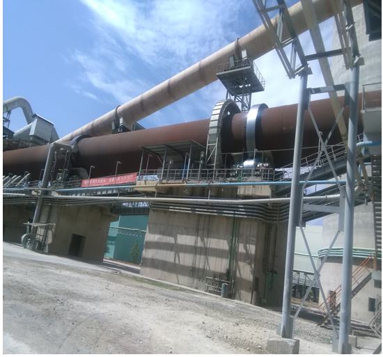
Figure.18. Rotary kiln
Startup and Shutdown Sequence of rotary kiln
There are two critical times when we must follow certain procedures in the operation of a rotary kiln to maintain its mechanical integrity:
- during the warm up of the kiln from cold, and
- When the kiln has stopped in the hot, operating condition.
Great care must be taken during the warming up of a rotary kiln from cold because there is the danger of closing the kiln shell to riding tyre gap, causing a constriction, lea ding to shell deformation, excessive shell ovality and difficulties in retaining the refractory lining within the kiln.
Principles to be followed for startup are
- Turning on the equipment of protecting system such as cooling water, lubricating system, etc.
- Starting tail equipment
- Starting master drive equipment
- Kiln shell cooling equipment
Principles to be followed for closedown are
- Stopping the master drive equipment
- Stopping tail equipment
- Stopping the lubrication equipment
- Stopping the cylinder cooling equipment
- Stopping the equipment of a protecting system, such as a cooling water system
REFRACTORIES
Those are ceramic materials capable of withstanding elevated temperatures without significant deterioration. The refractories must have good hot strength, resistance to abrasion, compatible chemical composition and sound thermal characteristics. The rotary section of the kiln, preheater, precalciner and cooler are lined with refractory materials in order to protect the steel casing and shell from high temperatures in the process. The role of refractories in cement kilns is multiple:
- To protect the steel shell against heat –Material and gas temperature inside the
rotary kiln surpass the maximum working temperature recommended for carbon steel. Without refractories the kiln shell would be destroyed by heat. As a result, as soon as the refractory lining fails, the kiln must be shut down for lining repair. The overheated areas on the kiln shell are commonly known as “hot spots” or “red spots”. - To protect the kiln shell against abrasion –Cement clinker is very abrasive and without refractories the steel shell would be damaged by abrasion.
- To minimize heat loss through the kiln shell – Part of the heat supplied to the kiln system is lost as radiation through the steel shell. Refractories reduce heat loss because of their relatively low thermal conductivity.
- To control the flow of material through the kiln – The kiln load travels under the combined action of kiln rotation and slope. Cam linings, dams, tumblers, and trefoils in the kiln oppose material flow allowing some control of material residence time.
- To promote heat transfer to the kiln load – Tumblers, trefoils, and profiled linings induce
material tumbling and mixing, which in turn promote heat transfer from gas to solids, from refractory to load, and within the load itself through agitation and surface renewal.
Types of refractories for cement kilns
Refractories used in the kiln, cooler and preheater are supplied either as pressed or fired brick, unshaped as monolithic products or in pre-cast, pre-fired shapes. The rotary kiln is almost entirely lined with bricks, while the preheater, cooler, and gas ducts are usually lined with castables, plastics or pre-cast shapes held in place by metal or ceramic anchors attached to the shell.
In the burning zone of the cement kiln a coating of clinker forms on the refractory lining and this further insulates and protects the kiln shell allowing long kiln campaigns between refractory lining repairs. The key to building up and maintaining this coating is stable operation of the kiln. Again the key to this stable operation is lack of variability in the feed and fuel supply rate, the chemistry of the feed and the calorific value of the fuel.
Disturbances in the kiln process can lead to the loss of the coating in the burning zone and a sudden increase in the rotary kiln shell temperature. Shell cooling fans can be applied to protect the steel of the shell and try to reestablish the coating on the refractory lining. Small red spots on the shell might be coated over in this way, but eventually the kiln has to be stopped to replace the worn sections of refractory lining.
Bricks are classified in four major groups according to their composition:
- Basic
- high alumina
- Fireclay
- Special materials
Basic Bricks
Basic bricks have magnesia or dolomite as their major component and a secondary mineral such as alumina, zircon, or spinel as a minor component. In most products the major component concentration varies between 60% and 95% by mass.
Magnesia alone is not used in kiln brick manufacture because of its poor thermal cycling properties. For this reason, magnesia is blended with a secondary mineral before it is pressed and fired into bricks. The secondary mineral confers thermal shock properties or modified chemical properties to the brick. Magnesia-chromium products were replaced with magnesia-alumina spinel products (due to disposal problems caused by hexavalent chromium rendered these products). Although magnesia-alumina spinel products do not present the excellent coatability of their predecessors, their thermal spalling resistance and alkali resistance far exceed those of chromium containing products. Magnesia-spinel products also resist reducing conditions better than magnesia-chromium products.
The magnesia-alumina spinel content in commercial bricks varies from 3% to 18% by mass. Higher magnesia products are usually more refractory but have higher thermal conductivity than lower magnesia products of similar porosity. Higher spinel bricks are more susceptible to chemical attack and fluxing than lower spinel bricks, but they exhibit better coatability and higher resistance to thermal spalling. The spinel itself can be sintered or fused, causing major differences in brick price and performance. Fused oxides are less reactive and less expensive than sintered oxides. It becomes clear from the previous facts that refractories cannot be compared only on the basis of their chemical or physical composition.
Dolomite brick is another important member of the basic brick groups. Due to their compatibility with clinker minerals, dolomite bricks have good affinity for coating, making them an excellent choice for burning zone applications. Most dolomite bricks receive additions of zirconia or other secondary minerals to improve their thermal shock properties and also to delay brick infiltration with clinker melt and alkali salts. Some modern dolomite bricks include additions of magnesia, while others include additions of pitch or tar to decrease brick permeability and reduce its susceptibility to chemical attack. Dolomite products offer the lowest direct cost among all basic brick, but their application has been confined mostly to the burning zone where the clinker coating is more stable. The most adverse property of dolomite products is their risk of hydration, requiring special care in packaging, handling, and storage. The shelf life of dolomite products has increased considerably by a special vacuum packaging and brick treatment.
High-Alumina Bricks
High-alumina products used in cement kilns vary in alumina content from 50% to 85% by mass.
To assume that all 70% alumina bricks are just commodities which is a risky generalization. For instance, a mullite based product presents greater thermal shock resistance than its bauxite counterpart. Similarly, a 60% andalusite brick resists alkali attack much better than its 60% bauxite equivalent. Higher alumina products, such as 80% or 85% are sometimes used in the discharge zone of the kiln because of their superior mechanical strength and abrasion resistance. These bricks sometimes contain 1 to 3% phosphorus pentoxide to improve their hot strength and abrasion resistance.
Some phosphate-bonded bricks are called oven-cured rather than fired at high temperatures. These products present better dimensional tolerances than their fired equivalents and are called chemically-bonded brick, as opposed to clay-bonded or ceramic-bonded.
In the calcining zone of the kiln, 70% alumina is the preferred choice unless alkali attack is so
severe that a lower alumina product is required. As a general rule, the resistance to alkali attack
increases as the alumina content decreases.
Fireclay Bricks
According to their alumina content and porosity, fireclay products are classified as high duty, super duty and semi-silica. Although widely used in the upper part of the calcining zone in the past, high-duty and super-duty bricks are gradually being replaced by high-alumina and semi-silica products. One of the reasons is the difficulty of keeping fireclay brick tolerances within acceptable limits. Another reason is loss of strength at higher operating temperatures. During kiln upsets, fireclay products tend to react with the kiln load, leading to abrupt lining failure. Semi-insulating products, although very low in mechanical strength, have the unique ability to react with alkali vapors in the kiln to form a thin glaze that protects it from abrasion and chemical attack. Their low thermal conductivity significantly reduces kiln shell temperature, a major advantage over tires. For best performance, these lightweight products must be installed with mortar.
When selecting a semi-insulating product, attention must be paid to its thermal expansion properties. Some products shrink at temperatures above 1000°C, a great risk in Precalcining kilns. Insulating bricks form a unique class of products. They are used only as backup linings for denser products in the preheater, cooler, and tertiary air duct. They lack the mechanical strength and refractoriness necessary to be used directly as the work lining.
Carbide and Zircon Bricks
In very special situations, zircon and silicon carbide bricks are used in the kiln with the purpose of minimizing ring formation in the calcining zone. Zircon bricks react with the clinker liquid phase when installed too close to the burning zone. Similarly, silicon carbide bricks promptly react with oxygen at high temperatures, especially in the presence of alkali or steam. Moreover, silicon carbide products have high thermal conductivity and low thermal expansion, making it difficult to get a tight lining in service. These disadvantages restrict the use of carbide and zircon brick to the calcining zone of the kiln.
Refractory properties of practical importance
Coatability; bricks must develop and keep a stable clinker coating.
Permeability; is a measure of the brick resistance to infiltration with gases and liquid.
Thermal conductivity a better pressed, less permeable product has higher thermal conductivity than a less pressed, more porous product.
Abrasion Resistance; occurs past the burning zone toward the cooler, where clinker is
already formed and the lining has no coating.
Reversible Thermal Expansion; governs the mechanical stability of the lining inservice.
Elastic Modulus ratio between stress and strain, it determines how elastic or inelastic a brick is under mechanical stress.
Chemical Composition an important tool for predicting material compatibility, coatability, elastic behavior, and resistance to thermal shock
Refractories fail at different times, in different kiln zones and the failure mechanisms usually
fall into one of three categories:
- Thermal stress including overheating and thermal shock
- Mechanical stress including compression, shearing, and pinch spalling,
- Chemical attack including alkali bursting, redox, hydration, and fluxing
Most refractory failures are caused by a combination of two or more stress factors, such as a
chemical reaction followed by brick melting, or lining densification followed by structural spalling. It is a well-recognized fact that stable kilns have refractory performance superior to unstable kilns of the same type and size.
Thermal stress
In the thermal stress category, lining overheating and sudden coating loss are the most common causes of brick failure. Overheating can be caused by many different factors such as feed starvation, excess fuel, kiln stoppages with the burner on, slowing the kiln down for long periods of time, defective burner pipe, and massive ash ring formation in the upper transition zone. Lining overheating can be restricted to a given kiln zone or even to a few rows of brick within the zone. Sudden coating loss, for instance, submits the lining to damaging thermal shock.
Mechanical stress
In the mechanical stress category, brick crushing is the most common problem. The main reasons for brick crushing are:
- installation problems such as too many shims, gaps and misalignment,
- excessive shell ovality
- kiln misalignment (doglegs)
- Improperly designed brick retainers
Chemical attack
In the chemical attack category, brick reaction with clinker melts and alkali salts is the most
common problem. The spinel phase in magnesia-spinel products reacts with clinker
minerals to form low-melting compounds. Dolomite reacts with sulphur and chlorine in a destructive way. Alumina bricks react with silica and potassium, forming compounds that burst the brick out. The intensity of the chemical attack increases with temperature, time, and
proximity to the burning zone. The disposal of alternative fuels in cement kilns has intensified chemical attack to the lining in all kiln zones, including the preheater and cooler.
Refractory applications
Modern kiln systems are lined with refractories in four different areas:
- preheater including inlet, feed shelf, precalciner and cyclones
- rotary kiln
- hood including burner pipe, kiln door and tertiary air intake
- Cooler including walls, bull nose, curbs and tertiary air intake
In DMC, preheater, precalciner, burner pipe, hood, kiln door and Cooler are lined with castables but rotary kiln and tertiary air duct are lined with bricks.
Preheaters
Preheaters are lined with brick, castables, and combinations of brick and castables. The best
performances are obtained from brick linings because bricks have more uniform properties, are
fired at high temperatures, and do not require the use of anchors. Bricks also yield more flexible linings than castables because of the larger number of joints in the brickwork.
Preheater linings consist of two layers of materials: a dense layer also called the work layer, over a layer of insulating material such as insulating castable, firebrick, or fiberboard. The insulation must be efficient to minimize heat loss through radiation because the surface area of the preheater vessels and ducts is large. The combined lining thickness rarely exceeds 250 mm, with the dense layer usually taking from 50% to 75% of the total lining thickness.
The higher vessels and ducts in the preheater only require fireclay, low-alumina brick, or castable.
Toward the kiln, where temperatures are higher, the lower stages 3, 4, and 5 work under high
concentrations of chlorine, potassium, and sulfur. In these areas the refractory must be less permeable and more resistant to alkali infiltration and attack. Care must be taken not to sacrifice chemical resistance for refractoriness because the maximum temperature in this part of the kiln rarely exceeds 900°C.
Another important requirement for refractories in this area is their ability to repel buildups. As
alkali sulfate and alkali chloride vapors progressively condense as salts on the lining surface, they reduce gas and solids flow, thus reducing preheater efficiency. If these buildups are not removed periodically through air or water blasting, they can completely block gas and material passage, thus forcing a kiln shutdown. Buildup removal with water requires high resistance to thermal shock from the lining. The material of choice for these areas is 60% or 70% alumina, low-cement castable, held in place by a combination of metal and ceramic anchors. If buildups are severe, zirconia or silicon carbide containing castables are much better alternatives since they do not hold buildups strongly. The use of silicon carbide in this application is not recommended if buildup removal is done with a water blast. Water promotes carbide oxidation at high temperatures.
Precalciner
For the precalciner, the riser duct and the feed shelf, the same recommendations apply. In
buildup areas the monolithic lining should not be gunned, shotcreted, or rammed, for maximum coating repellency.
The lining inside cyclones and the flash calciner is usually a combination of brick on the cylindrical surfaces and castables on the conical sections, roof, vortex finders, and inlet chamber. The calciner lining must also resist reducing conditions created by incomplete fuel combustion.
Rotary Kilns
Modern rotary kilns can be safely lined with just two types of bricks:
- High alumina in the calcining and discharge zones,
- magnesia-spinel in the lower transition, upper transition and burning zones
Many new kilns have been successfully commissioned with this simplified lining configuration, with good results. Some other kilns are lined with dolomite brick in the burning zone, magnesia-spinel brick in both transition zones, and high alumina in the calcining and discharge zones. The choice between dolomite and magnesia spinel in the burning zone depends upon a series of factors such as coating stability, type of fuels injected in the burning zone, insufflation of sodium carbonate or calcium chloride in the burning zone, and also the kiln run factor. The advantage of magnesia-spinel products over dolomite in the burning zone is their better resistance to structural spalling during coating loss or removal. The disadvantages are higher direct cost, lower coatability, and spinel reactivity with clinker melt.
The length and relative position of each kiln zone is a function of several factors such as kiln type, kiln dimensions, cooler type, fuel properties, burner design and position in the kiln, raw mix burnability, coating stability, and amount of liquid phase at different temperatures.
Kiln hood
The next area of concern is the kiln hood, a transition chamber between the kiln and the clinker
cooler. Temperatures in the hood are higher than those in the preheater, and potassium attack is a factor in refractory selection. Another factor of concern is the high concentration of abrasive clinker dust that could penetrate behind the refractory lining, pushing it in until it collapses. The most suitable material for hood walls is fireclay or low-alumina brick, followed by pre-cast, prefired shapes and cast-in-place linings. On average, shotcrete or gunning mixes do not outlast the previous alternatives because they lack uniformity of properties. From a purely cost/benefit standpoint, brick lining is the best alternative. Pre-cast, pre-fired shapes made with low-cement castables usually last from 3 to 10 years without maintenance in cooler walls.
The back wall and the hood ceiling can be rammed with refractory plastic, gunned, sprayed, or
formed, and cast. The main wear factors in these areas are clinker dust, alkali attack, and
anchor failure. In some kilns the back wall is equipped with air blasters to eliminate clinker
buildup. The use of silicon carbide materials in this application could be advantageous.
Burner Pipe
The burner pipe is usually lined with 75 to 100 mm of plastic or castable, held in place by metal anchors. Anchor failure and differential expansion are the most frequent reasons for burner pipe failure. Consequently, it is important that the metal anchors are the floating type. Usually only the first 500 mm from the tip of the burner become damaged in service. This is the area that requires the most attention during material selection and installation.
Clinker Cooler
With modern, high-efficiency coolers, the secondary air temperature surpasses 1000°C, thus requiring more refractory products around the hood. Metal anchor failure under thermal stress became common, requiring stainless steel of higher grade and caliber. Ceramic anchors are required in the hottest areas. In some extreme cases, basic brick has been successfully used in the hood. In the cooler, the three sidewalls before the bull nose can be lined in many different ways. A cost effective alternative for this application is pre-cast blocks individually anchored through the cooler shell. Anchoring the blocks inside the shell defeats the main advantage of
this system: quick lining repair. The material of choice for the blocks is 70% alumina, low-cement castable. If cooler buildups (“snowmen”) are severe, then the blocks can be cast with silicon carbide to take advantage of its non-sticking properties. The air blasters are still required between the carbide blocks.
The bull nose is one of the most difficult areas for lining stability. Usually the wear mechanism is dust penetration behind the lining, followed by anchor overheating and shearing. The best lining alternative is interlocking pre-cast shapes anchored to a hollow box beam. Cold air is blown into the box to cool down the anchoring system. The refractory material must resist constant abrasion from hot clinker dust and frequent temperature changes.
At the grate level, refractory curbs are used to keep the clinker from eroding the walls. Curbs are usually formed and cast in place, requiring careful heat up because of their massive size. Here, too, pre-cast, pre-fired, high-alumina curbs make the best lining alternative. The use of 2% by weight steel fibers in this application is highly recommended. The fibers increase the tensile and flexural strength of the lining.
Walls in the cooler can be advantageously lined with inexpensive fireclay brick. Brick linings in the cooler, when properly anchored and mortared, should last no less than 10 years without repairs.
The cooler roof is best lined with plastic or a good quality shotcrete mix, anchored by a combination of metal and ceramic anchors. Another cost effective alternative is to use pressed and fired shapes directly suspended from steel beams.
CLINKER COOLERS
In cement manufacturing, formation of clinker nodules occurs at the entrance to the hottest part of the kiln with a material temperature of around 1280°C. The clinker is preferably in the form of 10-mm to 25-mm size nodules that exit from the front end of the kiln into the cooler. It is critical that cooling of the clinker is rapid to secure a phase composition that imparts adequate cementitious properties. It is equally important that the heat exchange between clinker and air is efficient to ensure proper cooling and at the same time maximize the recovery of heat to secondary air, tertiary air and the related process requirement.
At the discharge end of the kiln, the clinker is red hot and contains around 1.0 million Btu per
short ton thermal energy. The clinker is also to some extent still reacting chemically toward
creation of various clinker minerals. The purpose of the clinker cooling is to recoup some of the
heat in the clinker, thereby making it cool enough to handle. We also want to stop the chemical
reactions in the clinker at the point most favorable to the cement quality.
Design project would include some of the following requirements:
- low capital cost
- optimum cooling rate for good clinker quality
- low clinker discharge temperature
- least possible impact upon the environment
- high heat recovery
- low power consumption
- low wear and maintenance cost
- reliable to operate
- causing minimal downtime
- easy to control so it delivers a steady flow of combustion air at an unvarying temperature to the kiln and calciner
Cooling of clinker takes place at two locations:
- In the kiln after the material passes the burning zone region, and
- In the specially designed clinker coolers after the material falls out of the kiln.
The rate of cooling can be critical to the clinker quality and performance of cement. The rate of cooling in the kiln is determined by the flame and resulting heat flux, flame temperature, and speed of material flow through the kiln. As the clinker temperature exiting the kiln is normally 1200°C to 1250°C, the clinker characteristics have been already largely established before the clinker enters the cooler. A long flame gives slow heat-up and slow cooling of the kiln charge before it falls from the kiln.
TYPES OF CLINKER COOLERS
1) Planetary Coolers
2) Rotary Coolers
3) Shaft Coolers
4) Grate Coolers
- Traveling grate cooler
- Reciprocating grate cooler
Now clinker cooling has been evolved with the new generation Claudius Peters cooler which is optimized, rationalized and well improved cooler, known as ETA – cooler.
ETA Cooler
General over view of the ETA Cooler
ETA Cooler is new clinker cooler type which has founded by Claudius peters. It incorporates a highly efficient transport system and significantly reduces the number of parts required and also without any conveying elements in the clinker bed, maintenance cost, wear and tear have been dramatically reduced.
Main advantages of ETA Cooler
- Reduced operating and maintenance costs (minimum wear)
- High availability
- No or minimized fall through of clinker fines
- Optimum clinker cooling
- Maximum heat recovery
Comparison of Grate cooler and ETA Cooler
ETA Cooler
- Each lane is driven separately
- Maximum Stroke length 400mm
- Individual stroke lengths for each lane possible
- Pyro process clinker temperature ≤65 0c above ambient temperature at cooler outlet
Grate Cooler
- All movable grate plates driven together
- Maximum Stroke length 120mm
- Identical stroke length for all plates
Effects on process and control for ETA Cooler
- Lower number of strokes in ETA Cooler reduced wear
- even clinker distribution over the cooler width
- Variable retention time of the clinker over the cooler width
Transport capacity replaces grate speed
- Transport Capacity: distance covered by all lanes during defined time
- Maximum transport capacity: Maximum Stroke length x number of lanes x number of strokes
- Actual transport capacity: Actual stroke length x number of lanes x number of strokes; Indicated in % of maximum capacity
The three major parts of ETA cooler
- Kiln drop zone; hot clinker from kiln is discharged onto this area.
- Recuperation zone; cooling air from this zone flows back to kiln as secondary air and to calciner as tertiary air.
- After cooling zone; cooling air from this zone goes to exhaust air.
Kiln drop zone
Requirements:
- Protecting against thermal and mechanical load
- Fast quenching of clinker / Efficient heat exchanging
- Distribution of clinker over cooler width
ETA Solution: HE Module
- Static inlet section; Static clinker layer: heat + impact protection
Optimum contact between air and clinker - Inclination of the static grate; Support clinker transport
- Narrowing at sides made of refractory
Distribution of clinker over cooler width
Recuperation zone
Requirements
- Maximum heat exchange
- Efficient transport of clinker
ETA Solution
- Longitudinal walls in Chamber 1
Air can be directed to where it is required - Controlled Side Aeration-CSA; Controlled aeration in critical areas
- Walking floor motion
Highly efficient clinker transport
Different stroke lengths of lanes possible
After cooling zone
Requirement
- Clinker cooling to required outlet temperature
- Efficient transport of clinker
ETA Solution
- Walking floor motion
Highly efficient clinker transport
Different stroke lengths of lanes possible - Chamber aeration
Simple aeration, low maintenance
Active Controllability of Clinker Bed / Heat exchange
Static inlet section efficient heat recuperation
Controlled Side Aeration Controlled side aeration with independent fans
Individual stroke length Variable retention time of clinker
over cooler width
Minimizing wear – Long service life
Reasons for wear:
– Clinker Movement and Friction
Possibilities to reduce wear High thermal load of steelwork
- Optimized transport system
- Optimized aeration
- Self-protecting design – wear and heat protection
- Hard-faced surfacing for areas exposed to wear
Transport System
The transport is based on the well proven walking floor system that has been in operation for materials handling. Eta cooler consists of parallel transport lanes which are moved together in the direction of the clinker transport (forward stroke) and individually or alternatively in groups retracted (backward stroke). The complete lower section of eta cooler is a modular design.
Static Inlet
The HE -Module opens up from the kiln drop point to the transport lanes by means of refractory concert. Here an optimal clinker distribution over width is achieved. With the HE-Module, which consists of astatic inclined grate the risk of snowman forming is virtually eliminated, while also ensuring a protective clinker layer on the module itself. The HE-Module is aerated via independent zones; each zone has its own flap to adjust the air volume. Due to flexibility of the air distribution, it is possible to control the kiln discharges conditions even with changing environment, due to the use of different fuels and raw materials fluctuations. Depending on the required throughput capacity, a corresponding number of parallel transport lanes are installed, each supported on independent rollers.
Due to Independent Lane Movement (ILM) (parallel individually driven aerated lanes), the flow behavior and material speed at the sides can be actively influenced. The slots for the air supply are integrated in the transport lanes by utilizing the Mulden grate plate principle. Each transport lane is sealed by means of labyrinth, which eliminates the need for a dust removal system. This together with the fact that the transport lane system is typically offered without any inclination makes the eta cooler design extremely compact.
Aeration concept
Since no installations are required inside the clinker layer the entire cooler bottom is fully aerated leading to uniform cooling and optimum recuperation. Additionally the eta cooler still makes use of the chamber aeration principles – a well proven aeration concept in conventional grate cooler design. However, in contrast to reciprocating grate cooler the eta cooler allows for longitudinal division in to chambers. This gives the advantage of chamber side aeration (CSA) and Independent Lane (ILM) Claudius peters can as no other cooler supplier, activity influence the two most important parameters in clinker cooling. This gives us the possibility to virtually eliminate such problems as red river.
Features
- Extremely compact design
- No dust removal system required
- Complete autogenous wear protection
- Long stroke = low grate speed
- Variable stroke length over the cooler width
- No conveying parts with in the clinker bed
- Less wear significantly reducing maintenance
- b) No obstructions to the clinker flow
- Constant transport efficiency over cooler life
- Controlled air distribution –chamber side aeration
Benefits
- Low construction height
- Modular design –quick to install
- Optimum cooling and heat recovery
- Optimal distribution of clinker across cooler width
- Lower operating costs
- High reliability
Drive system
The eta cooler is equipped with an independent hydraulic cylinder drive for each lane. Depending on the number of transport lanes, the structure is modular and utilizes standard part, which minimizes maintenance and adjustment. The hydraulic cylinders attributed to each transport lane enable along lane stroke, which is controlled by an integrated continuous position measuring system.
Eta motion Control Center controls and monitors all functions of the lane/ cylinder motion. This hydraulic control system continuously measures the position of the cylinder without contacts to ensure the stroke length required for each individual lane.
Temperature Measuring Device
The gas temperature within a clinker cooler is important aspect of the process parameters of the system, Claudius peter has developed an infrared sensor for quickly and accurately measuring the gas temperature.
- Infrared measuring sensor with 30c per second reaction time
- Measuring range from 0 – 8000c and 500 – 15000c
- Easy installation of probe
- Minimal maintenance requirement
- Low investment costs with return of investment (ROI) in months
In conclusion, whether it is a new plant or a conversion, the eta cooler offers the most efficient operation in terms installation, Heat recovery, transport efficiency, reliability and maintenance costs.
Clinker hammer crusher
It is an impact type with high speed rotor (280rpm) and 330rpm-1320mm diameter. The high speed of hammer crusher generates considered dust, which needs to be considered when positioning the cooler’s exhaust air duct. This crusher has more efficient crushing with longer machine life and minimal maintenance
Cooler Efficiency
Cooler efficiency can be divided in to two groups
- Internal thermal efficiency
- External thermal efficiency
- Internal Thermal Efficiency is using the recovered heat in burning process
- Secondary air heating in primary firing
- Tertiary air heating in Calciner firing
- External Thermal Efficiency is using the recovered heat for other process
- Raw mill, Coal Mill and Cement mill drying
- Heating and power generation
Speed of Clinker Cooling
Rapid cooling
- prevents growth of crystals and its size; gives suitable clinker nodule
- solidify the clinker in to glass state
- Improve C3S and reduce C2S leads to
- Easy grindability
- Lower energy consumption
- Improve hydration and cement Strength
The clinker cooler has the following tasks to fulfill:
- Process internal heat recuperation by heat transfer from clinker to combustion air
- Reduce clinker temperature to facilitate clinker handling and storage
- Provide maximum cooling velocity to avoid unfavorable clinker phases and crystal size
Typical Grate Cooler Problems
Red river
The infamous red river is one of the most feared problems with grate coolers. Due to segregation, fine clinker has always its preferred side. Different bed resistance on either side and only one air chamber across the entire width often cause fluidization of the fine clinker lying on top. This fluidized clinker does no longer follow the speed of the grate, but shoots much faster towards the cooler discharge end. Because the residence time of that fine clinker is much reduced, it does not follow the general cooling curve and forms a red hot layer on top of the regularly cooled, already black clinker; hence the term “red river”.
It is not the missed heat recuperation, but the red hot material being in touch with cooler walls
plates and side seals in the colder area where such temperatures should normally not occur.
Premature destruction of those pieces results in poor availability, high maintenance and ultimately in loss of production and sales revenues.
Snowman
The sticky consistence of the hot clinker leaving the kiln combined with the compaction at the drop point often leads to formation of solid clinker mountains on the grate. Not permeable for cooling air, they grow larger and disturb the flow pattern of the clinker in any critical inlet area.
Segregation
Due to its physical properties, the clinker is lifted by the kiln rotation before it is discharged into the cooler. Installation of the grate axis offset from the cooler axis should compensate for this effect. However, since discharge behavior of finer and coarser clinker particles differ from each other, the clinker fractions are not evenly distributed across the grate. Fines are discharged later and are thus found predominantly on the rising side of the kiln shell.
Air breaking through
Due to the different resistance of the clinker bed and the fear of overheated plates, too much air is put on the first grate compared to the clinker bed. The result is air shooting through the bed, hardly taking any heat and thus not contributing to the heat exchange.
Terms needs to be known
Cooling air
Is the air which passes the clinker thus being heated up while cooling the clinker. It
corresponds approximately to the combustion air requirement, only grate coolers allow additional air for better cooling.
Primary air
Is the air which is required for proper functioning of the burner. Ambient air insufflated by a separate small fan plus the air from a pneumatic transport system, amounting from < 10% up to > 30% of the air required to combust that fuel. Some precalciner burners are equipped with primary air fans (for cooling) as well.
Secondary air
Is the hot air entering the rotary kiln via clinker cooler. Its flow is determined by the combustion of the burning zone fuel. While cooling the clinker, it reaches temperatures of 600 to over 1000°C, depending on type and condition of the cooler.
Tertiary air
Is that part of the combustion air which is required for combusting the precalciner fuel. It is extracted from kiln hood or cooler roof, and then taken along a duct (tertiary air duct) parallel to the kiln to the precalciner. It reaches temperatures near or equal to the level of the secondary air.
Middle air (grate cooler only)
Is extracted from the cooler roof needed when drying of process materials requires a temperature level which is higher than the waste air. If the quantity is small, up to 450°C can be expected at normal cooler operation.
Waste air (grate cooler only)
It is also called cooler exit air or cooler excess air. The total cooling airflow from the fans is normally higher than the flow required for combustion (tertiary + secondary air). The extra air, which has normally a temperature of 200 to 300°C, must be vented to ambient via a dedusting system.
False air is cold air entering the system via kiln outlet seal, burner opening, casing or clinker
discharge. It either dilutes secondary air thus reducing recuperated heat or adds load to the waste air system of grate coolers.
Specific air volume
Is airflow per kg of clinker (m3/kg cli, Nm3/kg cli). Independent of the kiln size, air flows of cooler systems can be directly compared.
Specific loads
Express the relation of clinker production to a characteristic dimension of the cooler (t/d m, t/d m2, t/d m3). Exact definitions vary with cooler type.
Radiation losses
From the cooler casing/shell are particularly important for planetary coolers, where they actively support the cooling of the clinker.
Efficiency
It expresses the quality of heat transfer from clinker to the air which is used for
combustion in the burning zone and precalciner firing.
FEUL TYPES
As Clinkerization process is an endothermic (heat absorbing) process it requires burning of Suitable fuel. Remember almost 40 % of the total cost spent for manufacturing cement is for fuel and power. The specific heat consumption of modern plant ranges 690 to 800 Kcal/kg clinkers.
The objective of firing in kiln is to convert the latent heat in the fuel to free heat and to transfer this heat to the charge in the kiln.
In the cement industry, coal, fuel oil and natural gas are the fuels used for combustion commonly. Optimum rate of combustion is achieved by appropriate time, temperature and turbulence.
Pyro process requires burning of fuel at two locations:
- Kiln – High grade heat
- Precalciner -Low grade heat
Types of Fuel
- Coal; Coal of Sub-bituminous category is mostly used
- Fuel oil; Oil is mainly used as start-up fuel
- Gas; Gas firing is very rare
- Alternate Fuels; Saw dust , Used tyres and other wastes are also used nowadays
Fuel oil
Mainly used for startup in all the cement plants.
Type Fuel oil
Gas oil, LDO, Heavy fuel oil
Heavy fuel oil is the mainly used oil in Cement kiln as it is comparatively cheaper. Fuel oil Composition (% by weight) 85 % Carbon, 11-17 % Hydrogen and 1- 2 % Sulphur.
Sulphur in HFO goes up to 5% and it is the major cause for built ups in cyclones / riser ducts. Viscosity of HFO varies according to oil type and temperature. A viscosity of 12-18 centistokes is required for satisfactory atomization of oil in most of the burners.
N.B The calorific value of HFO is 9000-10,000 Kcal
Fuel oil Preparation
1) Heavy oil to be treated for
- Heating to constant temperature and desired viscosity
- Pressure needed for atomization
- Proper flow to burner
- Proper oil spray angle
2) Preheating can be done using oil or electric heaters
3) Oil preheating temperature limit: 110 0C, as it is the flash point of heavy fuel oil
4) Interlock arrangement for oil flow to avoid explosion problem for safety
Fuel oil Atomization
- Ensure proper preheating temperature to achieve the required viscosity for atomization
- Optimum size of oil droplets is 80 – 100 microns
- Too finer droplets will not mix with air well
- Too coarser droplets will take more time to burn
Effect of large oil droplets:
- Takes more time to burn
- Creates CO even at elevated temperature
- Has tendency to fall out of the flame and drop burning on charge
- Reducing conditions will get created and product quality will get affected
NB; Viscosity and Pressure needs to be controlled to control oil droplet size.
Fuel oil Flow regulation
Oil temperature, pressure and flow rate are monitored by the burner station with alarms and tripping controls. Discharge nozzle orifice to be selected according to the desired flow rate with fixed Orifice and changing oil pressure. Oil pressure can be varied between 25 to 50bar.
Two channels (Axial and Radial) give shape to flame.
Increase in Radial (tangential) oil will give large spray angle and wider flame with appropriate variation in primary air. To increase the oil spray rate both radial and axial pressure can be raised. Oil Temperature and pressure before the burner station to be kept constant to avoid disturbances in the oil atomization and oil flow rate.
With variable Orifice and Changing oil pressure
- Adjustable needle valve principle for flow control
- Displacing the needle changes the area of the nozzle( Ring shaped)
- Spray angle of oil is adjusted separately by giving the oil more or less rotation
Fuel oil Burners
- For heat economy choose burners with low primary air
- Burner should have high primary air velocities and air pressure
- To ensure good flame with oil go for flame momentum 1200 to 1500 % m/sec
- Optimum flame momentum is slightly higher with oil than for coal firing
Coal
Coal is originated from Plant derived organic remains. It is a fossil or organic sedimentary rock formed by the action of temperature, pressure on plant debris which is associated with moisture and minerals. It is also another form of carbon, as graphite or Diamond but a complex mixture of organic chemical substances containing carbon, hydrogen and oxygen. Small quantity of nitrogen, oxygen and some non-organic minerals also present in coal. Organic compounds constitute more than 50% by weight.
Coal Characteristics
- Coal represents widest range of qualities
- Compared to Oil and Gas, the Hydrogen in coal is fairly less
- As the coal becomes older, gas forming elements (H,N,O) reduces and fixed carbon increases
- Coal firing gives less dew point of flue gas
- The difference between Gross and Net Calorific value of Coal shall be 200 – 300 Kcal / kg only
- Calorific value of Coal depends on the contents of inert substance like moisture and ash
- For aged coals like Bituminous and Anthracite coals increase of hydrocarbons (Volatiles) will increase the Calorific value.
- For young coals, increase of Volatiles will decrease the Calorific value due to presence of more of inactive O2 and N2 in the volatile
- Sulfur in coal is a vital factor for coating build up in preheater. This will vary from 1 to 1.5% and may go as high as 5%
Major classes of coal are
- Anthracite
- Bituminous
- Ligneous
The Concept of rank
Rank is an expression of the Fixed Carbon Content of the Coal. Fixed Carbon is the amounts of Carbon left after treating the coal to a specific temperature say 925 or 950 0C. General Ranking is Peat, Lignite, Bituminous, and Anthracite with corresponding Fixed Carbon contents increasing from about 29% to about 95 %.
The rank of coal implies
- Progressive increase in Fixed Carbon content
- Progressive decrease of volatile content
- Progressive decrease of the Hydrogen and Oxygen content
- Progressive increase of the Calorific value
Chemical composition and Properties of Coal
Coal is chemically analyzed based on
- Proximate analysis which gives the amount of moisture, volatile matter, ash and fixed carbon in coal
- Ultimate analysis which gives the amount of elements namely Carbon, Hydrogen, Oxygen and Sulphur
Coal is also analyzed for
- Calorific value
- Contents of alkalis and chloride
- Grindability, Abrasion and Safety Index
Coal ash is also analyzed chemically which is very vital for raw mix design.
The calorific value of coal is ranged between 5900-6000 Kcal.
Moisture in Coal
- Reduces calorific value
- Hinders the ignition
- Reduces the flame temperature
- Slows down the rate of combustion
- Increases the burn out time
- Increases the flame envelope
- Increases the risk of flame instability
- Caking problem in fine coal bin and disturbed coal flow
- Increases the specific heat consumption
- Increases exhaust gas quantity and ID fan power
Free moisture
The moisture removed by air drying just above the room temperature and determined by drying of coal of a standard amount for 24 hours at 30 0C.
Hygroscopic moisture
Moisture bound in the air dried sample and determined by heating for some time at a temperature above 100 0C.
Total moisture
Sum of free moisture and hygroscopic moisture
Volatile Matter
- Rough indicator of the combustivity of coal
- Volatile matter is the hydro carbons present in the coal, which evaporates first when a dried coal is heated
- Higher Volatile matter leads to rapid oxidation and shorter flame
- As the rank approaches anthracite, the ignition temperature raises and ignition becomes difficult and the volatile matter is lesser
- A minimum of 22% is required for flame stability
- Volatile matter is determined by heating the coal sample in a special oven at 900 0C for 7mins
VM = (The % loss of mass) – (% of total moisture)
Other factors affecting the combustivity are
- Final temperature reached
- Heating rate
- Particle size
- Residual coke reactivity
Steps in combustion of Volatile matter
Volatile Matter Devolatilization Ignition Combustion of volatiles
Ash in Coal
It is residue left after combustion which is merely an inert diluent and influenced by mainly chemical composition and thermal properties. Ash differs in mass as well as composition depending upon the mineral matter from which it was formed. It can also Influences the reactivity of coal and lowering the calorific value and delaying the ignition of coal which intern affects the specific heat consumption and clinker to raw meal ratio in clinker production.
Analysis of coal ash
- Ash is analyzed for Loss On Ignition (LOI) and main oxides of interest in cement industry
- Very important factor for designing the raw mix to arrive a particular clinker analysis
- Alkalies, chlorides and sulphur in the coal ash are also found out on the basis of their concentration in coal sample
Sulfur in coal
- Higher sulfur content in coal leads to build ups in kiln inlet and lower cyclone stages
- Sulfur rich coating tend to form at points where false air enters the kiln system or where high turbulence occurs
Calorific value
In operation of the cement kiln, CV is the most important quality of coal.
- Maximum theoretical amount of energy available from a coal is calculated from CV
- A high ash and moisture content decreases the calorific value
Gross Calorific value (GCV) – Latent Heat of Vaporization of steam = Net Calorific value (NCV)
For low grade coals with high moisture, the NCV will differ significantly from GCV
Factors affecting the Heat Value are;
Moisture
- Reduces the heat value as it absorbs heat for vaporization and to reach the exhaust gas temperature
- Reduces the flame temperature by cooling effect
- Increases the specific heat consumption
Ash
- High ash reduces the heat value and flame temperature
- Higher ash content delay the combustion
- Reduction in clinker production
Volatile Matter
- Increase in VM increases the reaction of fuel
- Shorter flame and reduction in bloom length
Effect of C, H, N and O2
Higher the hydrogen content, higher will be the CV
* Net heat value of H2 = 28450 Kcals/ Kg of H2
* Net heat value of Carbon = 8083 Kcals/ Kg of carbon
- Nitrogen dilute the heat value of coal as it is the inert substance
- O2 present reduces the air requirement
- As the presence oxygen reduces the combustibles proportion, it reduces the heat value
Coal preparation
It involves both drying and grinding process. Control parameters will be the moisture content and fineness.
Moisture Content
- Important role in firing process and safer operation of the coal mill plant
- Higher the hygroscopic moisture in the raw coal, higher will be the residual moisture in the fine coal
Fineness
- Important to achieve a complete combustion in Kiln and Calciner
- Calciner coal to be ground finer as the firing temperature is lower
- The optimal fineness is a function of volatile matter as the burn out time for higher volatile coal is lesser
- Coal having a higher Hard groove index is easier to grind and the power consumption for grinding is more
Low Grade Coal
- Reduces the production cost
- Reduces the additives consumption
- Increases the required raw meal LSF
- Use of modern burner, blow the coal ash high up into the kiln and thus ash coating around the clinker nodules is reduced
- Hot primary air, more fineness of coal will give a better result in the usage of high ash coal
- When the ash content increases, the specific heat consumption increases due to the addition of ash (Cold) instead of (Preheated) raw meal
- Preheater exhaust gas temperature as well as the specific gas volume also increases when using the high ash coal
Five Stages in burning of a coal particle
- Heating
- Pyrolysis
- Ignition
- Combustion of Gases
- Combustion of coke residue
Heating – Instantaneous coal will reach the burning zone temperature in about 50 to 100ms.
Pyrolysis – Driving out the volatile matters CO, CH4, C2H6, H2,NO, SO2 etc. with about 200-300oC.
Ignition – First, gases released get ignited and burn with oxygen available in the primary air and the coal particle will be surrounded by a burning gas film consisting of gases released form the coal.
Combustion of Gases – The penetration of oxygen into the gas film by diffusion where it combines with the out flowing pyrolysis gas. The diffusion rate of oxygen is more important as it is comparatively slower than the reaction of oxygen with the pyrolysis gas. Better mixing of fuel and air and high temperatures increases the diffusion rate.
Combustion of Coke– Penetration of oxygen and reaches the particle and burning to yield CO which in turn yields CO2.Here also, diffusion of oxygen is the rate determining reaction .
Rate of combustion of coal is influenced by
* Particle size of coal
* Grade of coal
* Surrounding temperature and oxygen content
* Aerodynamic condition of the combustion chamber
For efficient combustion of coal
- Sufficient oxygen must be available to mix with the fuel
- A certain temperature must be maintained to ignite the fuel-oxygen mixture
- Sufficient time must be available to accomplish complete combustion while the fuel is in suspension in combustion chamber
- Evacuation of combustion products from the combustion chamber as soon as they are formed
- Relative motion between air and fuel particles in the system with high degree of turbulence
- The surface of the coal particle is another controlling factor, and the larger the surface , the quicker the combustion
- The surface of area of the micro pores is the major part, which are partly natural and partly created by the voids of the escaped gases from the pyrolysis
- Young coal contains more micro pores compared to older coal. Hence old coal needs to ground finer.
The oxygen required for firing is obtained from the combustion air
In the kiln system, the three sources of combustion air are
- Primary air
- Secondary air
- False air
Primary air, Secondary air, false air provides theoretical combustion air but if excess air is included it gives actual combustion air.
Quantity of combustion air in kiln system is adjusted by the preheater fan speed. Lack of combustion air in kiln is indicated by kiln inlet O2 analyzer (<1%)
For efficient combustion O2 should be
0.5 to 1.0 % at Kiln inlet
0.5 to 1.0 % at Calciner
3.5 to 3.5 % at preheater exit
CO should be < 500 PPM in all places
ALTERNATE FUELS
Other than the indigenous high ash coal, alternate fuels used are
- Imported coal
- Natural gas
- Pet coke
- Rubber tyres
- Bagasse
- Rice husk
- Natural gas comprised mainly methane (70-90 %) and propane (0-20%) and the calorific value will be in the range of and 8000 – 9700 Kcals / m3
BURNER
The function of the burner is to introduce the fuel into the burning zone. The propagation of the combustion process depends on how fast the combustible comes into contact with oxygen. It is therefore the essential function of the burner to regulate this mixing process adequately in order to achieve a correct flame shape. This process must take place in such a fashion that the heat is released at exactly the right place without producing any damaging effects and without producing excessive pollutant elements such as NOx, SOx and CO. Consequently, any optimization of the burning process must start with the correct adjustment of the flame.
In the sintering zone of rotary kiln, where the temperatures is highest over 1400°C required in the of a cement kiln to make the final combination of the clinker. The thermal energy to reach these process temperatures is input to the kiln through the main burner of the kiln, through the kiln hood and into the rotary section of the kiln.
There are a number of requirements of this main burner
- To deliver the required fuel in a stable, consistent, thermally efficient and safe manner
- To allow the amount of fuel delivered to be adjustable to the needs of the process
- To operate reliably over the long interrupted campaigns of days, weeks and months that are required of cement kilns
- To deliver that fuel in a way that does not compromise the ability of the other elements of the cement kiln process to operate over the required long, uninterrupted campaigns.
- To be adjustable to ensure the production of the clinker to the required quality in terms of combination and hydraulic reactivity.
- To minimize, as far as possible, the emissions from the cement kiln.
- To allow the burning of multiple traditional and alternative fuels on the kiln.
The fuels are injected into the kiln through the main burner, together with the primary combustion air, and spontaneously ignite as they encounter the high temperature in the kiln. Ensuring this ignition close to, but not on the burner tip is the first requirement for stable and safe operation. Fuel oil must be adequately atomized and coal must be ground to a residue on a 90µ sieve equivalent to half the volatile content and a residue of <2% on a 200µ sieve for stability. Position of the burner in the kiln is parallel with the kiln axis and in the center of the kiln cross-section but in large diameter kilns the burner is sometimes positioned offset from the center of the kiln cross-section towards the bed of material to increase the heat transfer by radiation to the charge from the flame.
Efficient combustion in a cement kiln flame is dependent on the availability and mixing of sufficient combustion air with the fuel for these reactions to take place in the flame. Only a minor part of the combustion air is provided by the primary air, which is blown into the kiln through the burner pipe. The remainder of the combustion air must be entrained into the flame and mixed with the fuel from the preheated secondary air which is drawn into the kiln from the cooler. The secondary air carries the thermal energy recovered from the clinker in the cooler back into the kiln. Maximizing secondary air and minimizing primary air is therefore the theoretically most thermally efficient way to operate the kiln.
The correct flame shape and burner adjustment has to be inferred from the clinker quality, shell temperature profile, coating tendency and the kiln inlet temperature, which should be <1100°C and the lower the better. The adjustment of the burner will be a critical factor in obtaining a stable and even coating on the refractory lining in the kiln, which in turn will assist in achieving the long, uninterrupted campaigns of operations that are required of a cement kiln. Generally burner can be divided in to two; Mono-channel and Multi-channel burner
Mono channel burner
It is the most simple burner design. With this burner type, coal dust and all the primary air is injected together through a single tube. Usually this type is used for long kilns, equipped with direct firing.
Characteristics of the mono channel burner:
- High amount of primary air (In combination with direct firing systems for coal, up to 50% primary air)
- Very limited flame shaping possibility
- High NOx formation
- Long and stable flame
Multi-channel Burner
For optimum flame shaping, when considering changing coal quality and different requirements from the point of view of raw mix burnability, burners with adjustable flame are to be preferred. In such burners, the primary air is usually divided into an axial and a radial component with the coal also introduced via a concentric ring tube. These burners are called multi-channel burners and are usually suitable for alternate or combined firing of coal, oil or even gas.
- Axial air is injected in the direction of the kiln axis (similar to a mono channel burner where all the air is injected in axial direction).
- Radial air (or swirl air) is injected with a direction towards the kiln wall. The swirl component of the radial air creates a rotating air flow along the kiln axis (similar to the threat of a screw) which is also pushing towards the outside, in direction of the kiln wall.
Since the radial air channel is located inside the axial air channel (both are concentric ring
channels), the radial air is opening up / widening the flow of the axial air. An increase of radial air versus axial air therefore creates a shorter flame. An increase of axial air versus radial air creates a longer flame. Besides flame shaping, the primary air (especially the axial air) also has to cool the burner
pipe.
Some of new generations of multi-channel burners are
- Pillard Rotaflam Burner
- FLS Duoflex Burner
- KHD Pyrojet Burner
- Unitherm M.A.S. Burner
- Greco Burner
M.A.S. (Mono Air duct System) – DMC burner type
The excellent operational experiences and the low NOx levels convinced major cement producers to choose the M.A.S. burner for replacement and for new plants as well.
Kiln capacity, heat consumption and clinker qualities are defined by:
- Correct composition of raw meal
- Chemistry
Burnability
- Meal fineness
- Correct burning conditions
- Fuel input and fuel distribution (kiln-calciner)
Process control
Kiln atmosphere (oxidizing)
- Kiln temperature profile
Flame shape control—burner design
- Clinker residence time
Burner position in kiln
- Clinker cooling
The three Stages of clinker burning optimization with M.A.S. burner
1st Stage: Control of flame shape by flame setting device
2nd Stage: Control of combustion intensity by adjustment of the M.A.S.-air pressure
- high pressur 180 mbar hot,short flame
- medium pressure 130-180 mbar
- low pressure < 130 mbar soft, long flame
3rd Stage: Control of flame core temperature by adjustment of the central air pressure
- By increasing the central-air pressure, the flame gets stable and the pressure in the flame root drops
Optimization of coal firing
Adjustment of coal dust injection velocity with coal nozzle setting.
Basics of injection velocity setting
- 25-30 m/s for hard combustible coal (pet coke, anthracite)
- 35 m/s for normal black coal
- 35-45 m/s for lignite
Design with two gas channels (axial gas and radial gas)
Wide, short flame: increase the radial gas pressure by opening of the radial gas flap
Long, narrow flame: increase the axial gas pressure by opening of the axial gas flap
Keep the axial and radial gas pressure over 0.8 bar g
If the radial gas flap is already 100% open, but the flame is not sufficient short, increase the cross section of the swirl gas nozzle.
Coating ring at kiln discharge
Trouble shooting
- Move the burner into the kiln with 20 cm steps
- Decrease central air pressure
- Decrease M.A.S.-air pressure
- Adjust softer, long flame by swirl setting device
Permanent coating ring at the beginning of the sinter zone
Trouble shooting
- Change the soft long flame to short hot flame each 4-8 hours
- For example:
Long flame: M.A.S.-air 100-140 mbar, flame setting device Pos.2-3
Short flame: M.A.S.-air 180-220-mbar, flame setting device Pos.5-7
Poor clinker burning, high free lime content in clinker, high CO-content in flue gas
Trouble shooting
- Increase the M.A.S.-air pressure
- Find the maximum flame core temperature with central air pressure
- Adjust wide, short flame by flame setting device
- For solid secondary fuel burning – change pressure of Pneumoswirl-air
- Check oxygen content in flue gas and pressure difference through the kiln. Increase the secondary air flow. (If ID fan doesn‘t have sufficient power, decrease tertiary air flow)
- Check the fuel quality: coal dust fineness, moisture (<1%) Increase coal dust fineness.
Brown clinker, reducing burning condition
Trouble shooting
- Check oxygen content in flue gas and pressure difference through the kiln. Increase the secondary air flow. (If ID fan doesn‘t have sufficient power, decrease tertiary air flow)
- Increase pressure of the M.A.S.-air and central air
- Change the position of the burner tip in kiln
- Check the fuel quality: coal dust fineness, moisture (<1%) Increase coal dust fineness.
- For solid secondary fuel burning- change pressure of Pneumo swirl-air
- For solid secondary fuel burning – decrease the particle size or fuel quantity
High kiln shell temperature, poor coating
Trouble shooting
- Adjust soft, long flame by flame setting device
- Decrease the central air pressure
- Decrease the M.A.S.-air pressure
- Change the position of the burner tip in kiln. Adjust the flame in kiln center
- Check the fuel quality: coal dust fineness, moisture (<1%).Increase coal dust fineness.
- Decrease the secondary air flow with ID fan
- Use the outer cooling of kiln shell with auxiliary fans
- Change chemistry of the raw meal
Parameters affecting NOx:
- Burning zone temperature
- Free lime
- LSF
- Secondary air temperature
- air flow characteristics (cooler type)
- Thermal kiln loading
- Kiln design –staged combustion in calciner
- Fuel grinding size and volatiles content
- Burner tip position in kiln
- Fuel surrounded by primary air (staged combustion)
- Low primary air amount (momentum)
- Close fuel ignition distance
- Mixing intensity of fuels (swirl number)
- Burner settings (avoid oxygen inside flame root)
Trouble shooting
Decreasing of NOx Emissions
- Decrease M.A.S.-swirl on the swirl setting device to a narrow, long flame shape
- Decrease pressure of the M.A.S.-air
- Adjust pressure of central-air (try the upper and lower limit)
- Increase coal-dust injection velocity
- For solid secondary fuel burning – decrease pressure of Pneumoswirl-air
- Change the position of the burner tip in kiln
- Decrease temperature of secondary air (if possible)
Burner position in rotary kiln
Initial position X=0 up to 1000mm
for coal- following kiln axis or fuel oil- horizontal (rotate around fix point)
Further optimization
- move the burner tip to the clinker
- keep the flame away from the coating
- find the best axial position of the burner
General considerations to burner axial position
Burner tip deep inside the kiln >> 0.5 m
- risk of reduced kiln capacity and high flue gas temperature at kiln inlet
- more straight flame
- better fuel ignition
- reduced risk of ring formation at kiln outlet
Burner tip inside the kiln < 0.5 m (usual position)
- increase of kiln capacity and reducing of the flue gas temperature at kiln inlet
- risk of uneven flame due to kiln outlet eddy (high turbulence of section air)
- worse fuel ignition
- risk of ring formation at kiln outlet or snowman in cooler
Axial burner position in rotary kiln
- Especially for rotary kiln with grate cooler a proper axial position of the burner is very important
- 20 cm movement of the burner moves the sinter zone up to 1m
- Sometimes NOx – emissions depends on burner position drastically
- The clinker mass composition as well clinker characteristics depend on length of the cooling zone within the kiln, means also defined by burner axial position. We recommend keeping 1200-1250°C clinker temperature at the kiln edge.
ELECTROSTATIC PRECIPITATORS
An electrostatic precipitator (ESP) is a particle control device that uses electrical forces to move the particles out of the flowing gas stream and onto collector plates. The particles are given an electrical charge by forcing them to pass through a corona, a region in which gaseous ions flow. The electrical field that forces the charged particles to the walls comes from electrodes maintained at high voltage in the center of the flow lane.
Once the particles are collected on the plates, they must be removed from the plates without re-entraining them into the gas stream. This is usually accomplished by knocking them loose from the plates, allowing the collected layer of particles to slide down into a hopper from which they are evacuated. They can collect particles sized 0.1 to 10 microns very efficiently. They are generally more efficient at collecting fine particles than scrubbers or cyclones.
Electrostatic precipitators take advantage of the electrical principle that opposite charges attract each other. A high voltage electrode negatively charges airborne particles in the exhaust stream. As the exhaust gas passes through this electrified field, the particles are charged. Typically 20,000 to 70,000 volts are used. A large, grounded flat metal surface acts as a collection electrode. Microscopic particles are attracted to this surface where they build-up to form a dust cake. Periodically, a rapper strikes the plate to knock the dust cake into a collection hopper.
Particle Charging
Our typical ESP has thin wires called discharge electrodes, which are evenly spaced between large plates called collection electrodes, which are grounded. Think of an electrode as something that can conduct or transmit electricity. A negative high-voltage, pulsating, direct current is applied to the discharge electrode creating a negative electric field. You can mentally divide this field into three regions. The field is strongest right next to the discharge electrode, weaker in the areas between the discharge and collection electrodes called the inter-electrode region, and weakest near the collection electrode. The region around the discharge electrode is where the particle charging process begins.
Corona Discharge: Free Electron Generation
Several things happen very rapidly (in a matter of a millisecond) in the small area around the discharge electrode. The applied voltage is increased until it produces a corona discharge, which can be seen as a luminous blue glow around the discharge electrode. The free electrons created by the corona are rapidly fleeing the negative electric field, which repulses them. They move faster and faster away from the discharge electrode. This acceleration causes them to literally crash into gas molecules, bumping off electrons in the molecules. As a result of losing an electron (which is negative), the gas molecules become positively charged, that is, they become positive ions. So, this is the first thing that happens—gas molecules are ionized
and electrons are liberated. All this activity occurs very close to the discharge electrode. This process continues, creating more and more free electrons and more positive ions. The name for all this electron generation activity is avalanche multiplication
The electrons bump into gas molecules and create additional ionized molecules. The positive ions, on the other hand, are drawn back toward the negative discharge electrode. The molecules are hundreds of times bigger than the tiny electrons and move slowly, but they do pick up speed. In fact, many of them collide right into the metal discharge electrode or the gas space around the wire causing additional electrons to be knocked off. This is called secondary emission. So, this is the second thing that happens. We still have positive ions and a large amount of free electrons.
Therefore, the process is considered to be comprised of the following components:
- Production of an electric field to create corona and ions
- Charging of the particles by the ions
- Effect of the charged particles on the electric field
- Migration of the charged particles through the fie
Ionization of Gas Molecules
As the electrons leave the strong electrical field area around the discharge electrode
they start slowing down. Now they’re in the inter-electrode area where they are still
repulsed by the discharge electrode but to a lesser extent. There are also gas molecules
in the inter-electrode region, but instead of violently colliding with them, the electrons
kind of bump up to them and are captured. This imparts a negative charge to the gas molecules, creating negative gas ions. This time, because the ions are negative, they too want to move in the direction opposite the strong negative field. Now we
have ionization of gas molecules happening near the discharge electrode and in the
inter-electrode area, but with a big difference. The ions near the discharge electrode
are positive and remain in that area. The ions in the middle area are negative and move
away, along the path of invisible electric field lines, toward the collection electrode.
Charging of Particles
These negative gas ions play a key role in capturing dust particles. Before the dust particles can be captured, they must first acquire a negative charge. This is when and where it happens. The particles are traveling along in the gas stream and encounter negative ions moving across their path. Actually, what really happens is that the particles get in the way of the negatively charged gas ions. The gas ions stick to the particles, imparting a negative charge to them. At first the charge is fairly insignificant as most particles are huge compared to a gas molecule. But many gas ions can fit on a particle, and they do. Small particles (less than 1 µm diameter) can absorb “tens” of ions. Large particles (greater than 10 µm) can absorb “tens of thousands” of ions. Eventually, there are so many ions stuck to the particles, the particles emit their own negative electrical field. When this happens, the negative field around the particle repulses the negative gas ions and no additional ions are acquired.
This is called the saturation charge. Now the negatively-charged particles are feeling
the inescapable pull of electrostatic attraction. Bigger particles have a higher saturation charge (more molecules fit) and consequently are pulled more strongly to the collection plate. In other words, they move faster than smaller particles.
Particle Charging Mechanisms
Particles are charged by negative gas ions moving toward the collection plate by one of these two mechanisms: field charging or diffusion charging. In field charging (the mechanism described above), particles capture negatively charged gas ions as the ions move toward the grounded collection plate. Diffusion charging, as its name implies, depends on the random motion of the gas ions to charge particles.
In field charging as particles enter the electric field, they cause a local dislocation of the field. Negative gas ions traveling along the electric field lines collide with the suspended particles and impart a charge to them. The ions will continue to bombard a particle until the charge on that particle is sufficient to divert the electric lines away from it. This prevents new ions from colliding with the charged dust particle. When a particle no longer receives an ion charge, it is said to be saturated. Saturated charged particles then migrate to the collection electrode and are collected.
Diffusion charging is associated with the random Brownian motion of the negative
gas ions. The random motion is related to the velocity of the gas ions due to thermal
effects: the higher the temperature, the more movement. Negative gas ions collide
with the particles because of their random thermal motion and impart a charge on the
particles. Because the particles are very small (submicrometer), they do not cause the
electric field to be dislocated, as in field charging. Thus, diffusion charging is the only
mechanism by which these very small particles become charged. The charged particles then migrate to the collection electrode.
Particle Collection
When a charged particle reaches the grounded collection electrode, the charge on the particle is only partially discharged. The charge is slowly leaked to the grounded collection
plate. A portion of the charge is retained and contributes to the inter-molecular adhesive
and cohesive forces that hold the particles onto the plates. Adhesive forces
cause the particles to physically hold on to each other because of their dissimilar surfaces.
Newly arrived particles are held to the collected particles by cohesive forces; particles are
attracted and held to each other molecularly. The dust layer is allowed to build up on the
plate to a desired thickness and then the particle removal cycle is initiated.
Particle Removal
Dust that has accumulated to a certain thickness on the collection electrode is removed by
one of two processes, depending on the type of collection electrode. Collection electrodes in precipitators can be either plates or tubes, with plates being more common. Plates can be cleaned either by water sprays or a process called rapping.
Rapping is a process whereby deposited, dry particles are dislodged from the collection
plates by sending mechanical impulses, or vibrations, to the plates. Precipitator plates are
rapped periodically while maintaining the continuous flue-gas cleaning process. In other
words, the plates are rapped while the ESP is on-line; the gas flow continues through the
precipitator and the applied voltage remains constant. Plates are rapped when the accumulated dust layer is relatively thick (0.08 to 1.27 cm or 0.03 to 0.5 in.). This allows the dust layer to fall off the plates as large aggregate sheets and helps eliminate dust re-entrainment.
Dislodged dust falls from the plates into the hopper. The hopper is a single collection bin
with sides sloping approximately 50 to 70° to allow dust to flow freely from the top of the
hopper to the discharge opening. Dust should be removed as soon as possible to avoid
(dust) packing. Packed dust is very difficult to remove. Most hoppers are emptied by some
type of discharge device and then transported by a conveyor.
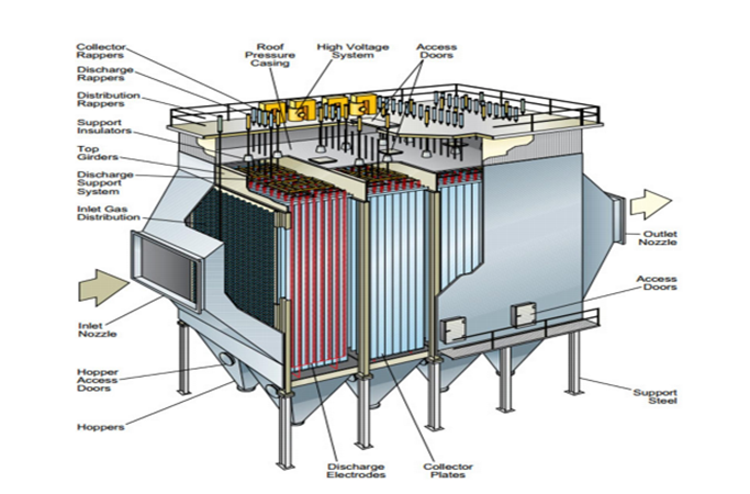
Figure.19. Electrostatic precipitator (ESP)
Material transporting system
There are at least six means of material transporting system from section to section in DMC, such as
- Deep Drawn pan conveyor
- Belt conveyor
- Bucket elevator
- Drag chain
- Air slide
- Screw conveyor
DEEP DRAWN PAN CONVEYOR WITH BUCKET ELAVETYOR
For clinker handling the Pan Conveyor type suits conveying routes with an inclination up to 30°.
This Pan Conveyor type is the ideal direct connection between cooler and clinker stock especially for applications with eta coolers. The design allows the Pan Conveyor to be arranged underneath the whole cooler length and to collect the fines from the dust collecting hoppers same as the clinker from the crusher.
The cold clinker are output from the eta cooler, then transported by deep pan conveyor and stored in clinker silo.
Features
- Accepts temperatures to 700°C
- Designed as a modular structure with standard components
- Profiled pans for high rigidity
- Minimum spillage
- Highly wear resistant chains with high yield strength
- High quality standards on all components
Benefits
- Efficient and reliable operation
- Reduced installation time
- Low operating costs
- Minimum and easy maintenance
- Low power consumption
- Low overall investment cost
- Outstanding service life
The characteristic profile of the pans with their contact-free overlapping offers high rigidity with large pan widths and a closed surface in the return stations. Stiffeners pressed into the side plates combined with a sealing edge of special design provide the tight fitting to avoid spillage. The coupling between motor and gear box can be hydraulic or flexible for soft start-up. Frequency converters adapt the conveying speed to the actual conveying capacity
Belt Conveyor
The main material transporting system consists of belt conveyor. The belt conveyor transporting system includes:-
Raw material like limestone, gypsum and sand are conveyed from the place they are naturally found to the main plant where their storage place is located,
- From storage area to proportioning house from proportioning to raw mill,
- From clinker silo to cement mill,
- From packing to loading.
The design of the belt takes the following point in to account:
The material design that includes strength and temperature resistance of the belt depending on the line where the belts are arranged .For instance if the conveyor belt is supposed to cover a long distance or to transport material against gravity, the tension that develops on the belt will be high. Hence the designer of the belt should give emphasis to strength. Whereas the belt is
Going to transport clinker needs to have high temperature resistance. Hence the selection for the production of such type of belt must take the thermal property of the material in to consideration.
The capacity of belt, this is directly related to the width of the belt i.e. how much amount of material it transports per unit speed and time .in the DMC transport systems, cross country belt conveyor, 1000ton/hr. transported from quarry to receiving silo.
Bucket elevator
Bucket elevator is one of the popular means transporting system in DMC cement factory. Wherever there is certain inconvenience for belt conveyors, it is worth going for bucket elevator. The fast-running bucket elevators can handle can withstand temperatures up to 350oC
- There are three bucket elevator transported from cement mill to air slid
- Three bucket elevator transported from air slid to cement silo
- There are six bucket elevators transported from air slid to packer machine. And also
- From drag chain output and air slide output to raw meal silo
- From cement air slide output to cement silo are accompanied by bucket elevator
- From homogenizing silo to preheater
Therefore, it is better to use the technology of bucket elevator. The drive mechanism looks almost the same as that of belt conveyors. The flow of material from this, it is possible to see that bucket elevators are intended to do their task as per the reason of selection mentioned earlier. Parts of belt bucket elevator
- Belt
- Belt clamping connection
- Bucket
- Drum disc
Drag/ Trough chain
Drag chain conveyors are used for horizontal or inclining transport of bulk materials (may- inclination 20o). Drag chain conveyors can withstand temperatures up to 350oC, and up to 400oC if fitted with special chains. 400- 500oC is allowed for a short period. Drag chain conveyors have a dust- tight casing of steel plate. In addition to the outlet at the drive station, the conveyor can be fitted with hydraulically-operated slide gates at points along the casing these types of transporting mean have the same mechanism drive and drive structure. The only difference they show is that the drag chain transports or conveyors relatively coarse materials whereas trough chain transports material usually very fine materials are transported in to air slid.
Air slide
As the name itself indicates air slide transporting system uses air blown by blower fans just below a material holding industrial cloth which is known as martin cloth. As the air vibrates the martin cloth due to the slope of the air materials including raw meal and cement it is used to convey fine materials by small ID fan under it
- From raw meal cyclone output to raw meal bucket elevator
- From cement meal cyclone output cement meal bucket elevator
- There are six air slid transported from cement silo to cement bucket elevator.
Screw conveyor
Screw conveyors are used for horizontal, inclined, or vertical transport of bulk and granulated materials. Screw Conveyors are designed for inclined transport (up to 8o’) of material with temperatures below 300oC this type of conveying mechanism is selected specially for material which appears to be semi-wet. Usually materials extracted from deducting process are transported with the help of screw conveyors. This system transports materials there are six screw conveyors transport materials
From cement bag filter outlet and cyclone to cement bucket elevator.
Off spec silo
Off spec silo is fitted with telescopic loading spouts including integral dust control to feed materials on the truck. It also used as a support for deep pan conveyor which carries clinker from hammer crusher.
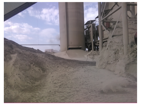
FIGUER.20. DMC off-spec silo
Clinker Storage
Clinker and other cement components are stored in silos or in closed sheds. Larger stocks can be stored in the open if the necessary precautions against dust formation are taken.
The output product from the grate cooler is stored in clinker silo before it is fed to the cement mill for conversion to cement. This storage is called clinker storage. The storage may be of silo type. Silo type clinker storage has the advantage that there is no dust pollution and spillage of clinker. The capacity of silo may vary from factory to factory. In DMC factory the capacity is 47500ton. Clinker will be discharged from the silo and transported to belt conveyor by deep pan conveyor and clinker bin in cement grinding plant by belt conveyer
The most common clinker storage systems are:
- Longitudinal stores with gravity discharge (limited livestock)
- Circular stores with gravity discharge (limited livestock)
- Clinker storage silos (high live stock; problems with ground vibrations can occur during Clinker withdrawal from the silo at certain silo levels)
- Clinker storage domes (limited livestock)
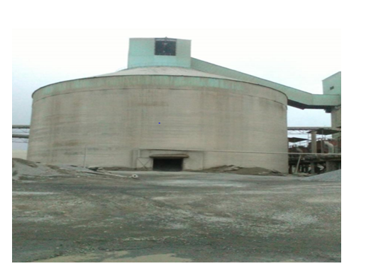
FIGURE.21. clinker storage silo
Challenges
Clinker silos usually have very large diameters and hold tens of thousands of tons of material. The material is very dusty and fed into the silo at relatively high temperature of approximately 100° C. The end-user’s main problem is to know the quantities of clinker stored in the silo at all times. This system can provide an accurate volume measurement in any sized clinker silo allowing the end-user to see how the material is distributed inside the silo and to accurately monitor inventory levels. Cement is perhaps the most important building material whose semi-finished material is clinker.so the clinker is stored in properly. But in derba cement factory the clinker is stored outside storage silo.
Cement factories produce clinker first in order to make cement. After its production, clinker is kept in storage until it is turned into cement determined strength results of the concrete made with this clinker. The remaining clinker was divided into three parts. One part was kept for one year in closed storage with a nylon cover; the second part was kept in closed storage at room temperature; and the last part was kept at open storage. Mortar strength results of these were also identified. The results showed that clinker kept in open storage had 12% more quality loss than that kept in closed storage.
Anything known as strength of cement is simply because hydration of clinker on the application of cement with water. Moreover this hydration is irreversible reaction. Hydrated clinker will be devoid of any strength. So whenever you plan to store clinker in open yard, always make preparation to safeguard it water, better you cover it with tarpaulin. Fresh clinker will become more and more hydrated the longer it is exposed to moisture, so it is important to keep it covered. However, if you are adding limestone as filler in your cement, there is a solution to using partially weathered clinker without any drop in mortar strengths.
FIGURE.22. DMC clinker stored outside silo
CEMENT GRINDING
Types of cement mills
There are basically 4 types of cement mills in use today
- Ball Mill
- Vertical Roller Mill
- Roller Press
- Horizontal Mill
Consider all investment key aspects
- Energy consumption
- Investment cost
- Maintenance Spare part
- Stock holding
- Availability
- Quality
BALL MILL
We have now passed beyond the cement kiln system to the final processing stage in the manufacture of cement. The cement finishes milling section of the cement factory. This is the final opportunity to get the quality of the cement right before it is delivered to the cement silos and on to the customers of a cement company.
The basic role of a cement mill is to grind the clinker produced in the cement kiln into a fine powder. This increases the surface area of the cement and the rate of reaction when the cement is mixed with water.
The clinker will be extracted from the clinker silo or storage and conveyed to the cement mill by belt conveyor. Clinker will age and lose some of its hydraulic potential in storage. The cement mill operator may well need to extract clinker from different points in the clinker silo to ensure this turn-over of the clinker stock. Perhaps some off-specification, or outside stored clinker must be blended back into the cement with the clinker. Controlling the rate of that blending of different clinkers will be an important task for the cement mill operator.
Dependent on the type of cement being produced other ingredients of the recipe will need to be loaded into the cement mill feed bins Ingredients such as pumice, gypsum and high grade lime stone 3-4% without change physical and chemical the clinker.
Different materials and differently stored clinkers have different “grind abilities”, meaning that some materials are harder to grind than others. Difficulty of grinding rises from gypsum<limestone<clinker When materials of different grind ability are being ground together then the softer material will be preferentially ground and concentrate in the finer fractions, while the harder material will concentrate in the coarser particles. As it is the clinker that mainly gives the strength development of the cement then it is the surface area of the clinker that is important.
This is why control should be residue as this ensures that the clinker particles are ground sufficiently fine, irrespective of the surface area which will derive from the preferentially ground limestone and gypsum. The problem of different grind abilities and preferential grinding of the softer materials is the reason why separate grinding and then blending of the finely ground materials is sometimes the strategy. In that way the fineness of the individual components of the recipe can be controlled with more consistent strength development of the cement. For the cement mill operator attaining these fineness targets is achieved by adjustment of the feed rate to the mill and the separator speed in closed circuit cement mills. Just as in raw grinding the finer the cement must be ground the lower the feed rate to the mill must be to reach that fineness. The mill motor continues to draw virtually the same amount of electricity so the unit electricity consumption in kWh/t rises with increasing fineness of grinding. However, cements are ground much more finely that kiln feed, and clinker is harder to grind than limestone. The unit electricity consumption for cement grinding is therefore much higher than for raw grinding. The majority of cement around the world continues to be ground on closed circuit ball mills. For cement grinding roll presses are sometimes employed as pre grinders pressing the clinker feed to the mill into slabs which are then finish ground in a single chamber ball mill. These combined roll press and ball mill circuits can have different configurations of separators in circuit with the roll press, ball mill or both dependent on the fineness of the cement being ground.
These combined roll press and finish ball mill circuits are most efficient with the ball mill having only one chamber and being charged with fine media for the finish grinding of the pressed slabs of clinker from the press. However, if the ball mill is set up in this way then it cannot operate without the roll press pre-grinding the clinker as there is no coarse media in the ball mill to initially crush the clinker.
The feed rate to a cement mill and the separator speed will be adjusted in response to quality control testing of the surface area or residue of the cement being ground. However, changing grind ability of the clinker or other components of the recipe can lead to changes in the residence time of the material in the mill. With a ball mill this is monitored via the small variations in the power drawn by the mill main motor, the sound of the balls striking the liner plates of the mill as the mill turns, the power drawn by the elevator to the separator, and the
Weight of rejects from the separator, PID loops controlling the feed rate to the mill in response to variations in mill motor kW, the sound detected by an electronic ear or the kW drawn by the elevator have been successfully employed on some cement factories. Sometimes the “total feed” to the mill is controlled by varying the fresh feed rate to the mill in response to variation in the weight of rejects being sent back to the mill by the separator.
If the material becomes easier to grind then the amount of material being recirculates from the separator to the grinding table will reduce and the pressure drop across the mill will fall. The PID loop then increases the fresh feed rate to the mill to bring the pressure drop across the mill back to target. Recipe control and fineness control via adjustments in the feed rate to the mill and separator speed are the main jobs of the cement mill operator. Temperature control is also important to dry any wet components of the recipe and to dehydrate the gypsum in the mill.
Same basic Mechanical Design specification
DMC Cement plant effective inner diameter of mill shell for the first chamber is 4.48m and for the second chamber also the same that one. Or 4.48m
In addition to effective length of mill shells are the first chamber is 4.215m and the second chamber is 8.715m, its usage pulverizing cement by closed circuit pulverizing method and production capacity are 3*120t/hr. cement fineness is 3200±100cm2/g. the mills rotational speed is 14.9r/min, and maximum charging capacity of grinding media is 280ton, power of motor 4500kw.and also the bin feeder hopper capacity clinker hopper capacity 890ton, pumice capacity 310ton and gypsum capacity 610ton.
Main features and operating principles
Main features
For this mill; it adopts center drive method, and uses two slipper bearings at both ends for support. The mill adopts combined partition plate and discharge grid plate to raise pulverizing efficiency. The ball mills are highly in efficient with more than 98% of the energy going out waste towards friction and heat generation. Conventionally raw materials (clinker, gypsum and pumice), were being ground in the ball mills. In the ball mills the material and the grinding media steel ball are brought together in a rotating tubular compartment.
Ball mill in closed circuit has the
- Lowest investment
- Lowest operating cost
- Lowest maintenance cost
- Highest availability
- Highest cement quality acceptance!
Major parameters for ball milling
- Temperature
- Size and Number of the balls
- Nature of the balls
- Rotation speed
Types of Ball Mills
- Drum ball mills
- Jet-mills
- Bead-mills
- Horizontal rotary ball mills
- Vibration ball mills
- Planetary ball mills
Ball mill& mill internals
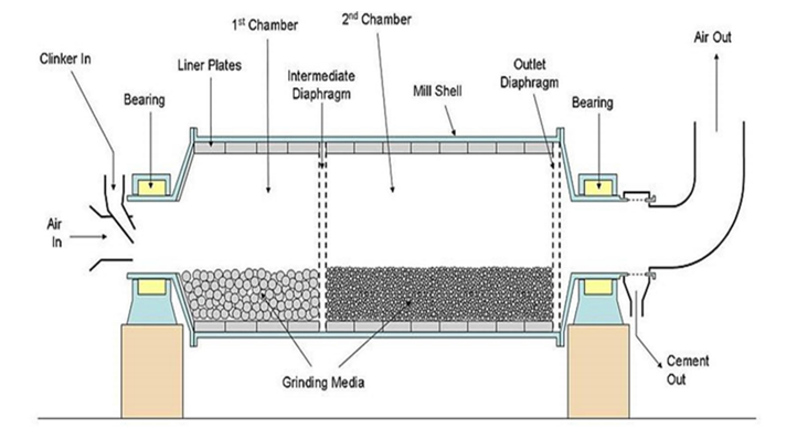
Figure.23. section of cement mill
Operating principles
DMC Plant operating materials are feed into mill’s coarse compartment through feeding device’s feeding leg, and then are pulverized by grinding media. . The material and the grinding media are lifted some distance due to the rotation of the mill. During lifting, the material is ground by compressive and shearing action. After rising to a certain height, the grinding media falls down creating size reduction by impact. Ball mill can be used for dry grinding and it is Closed Circuit Mill In these mills the fine output (cement) passed through bag filter. The heavy material from the mill is fed to a separator by a bucket elevator for separating into product and rejects. The rejects are returned to the mill inlet. The closed circuit mills have a better control on the particle size distribution fineness controlled. It operates in the closed circuit with regrinding to achieve maximum grinding efficiency and high flexibility of product quality. Ball mill are operate in closed circuit, the circulation load is monitored by weighing the flow of reject materials from the separator. There are three cement mills, each of them have capacity to grinding 120tons/hr. The power requirements of each cement mill is 6mW
Cement mills have two chambers:
- First chamber
- Second chamber
First chamber: the diameter of steel ball is 60-95mm
Plate used in the first chamber for rising material is raising plate
Second chamber: diameter of steel ball is 25-40mm
Classifier plate is used in this chamber plate
Damper plate is used to separate first chamber and second chamber.
Unground material in the cement mill is transport by bucket elevator chain to separator, which
Has conveying capacity of 500tons/hr.
Factors affecting ball mills
- Feed characteristic (grindability, moisture, etc.)
- Cement fineness
- Equipment design & plant engineering
- Operations & maintenance
- Use of clinker extenders (Additives)
- Use of grinding aids (Admixtures)
Vertical Roller Mills
The vertical roller mill has become the obvious and preferred tool of choice for raw milling due to higher output rates, lower energy consumption, drying capacity, dependability, versatility, etc. These mills offer simplicity by combining the functions of secondary ~ tertiary crushing, drying, grinding and classifying in one compact machine. Vertical roller mills are available with two, three, four and six rollers.
The characteristic of these mills is that the size reduction is effected by rollers on comparable grinding elements traveling over a circular bed of material. The material after passing under the rollers is subjected to a preliminary classifying action by a stream of air sweeping through the mill. The air at high velocity lifts the material to the classifier which separates the coarse and fine particles. The fine particles are entrained and the separated coarse particles fall back to the table. The separator could be either static or dynamic. The fine particles are collected later in a cyclone.
The advantages of Vertical Roller Mills
Vertical roller mill is comparatively more energy efficient and on an average these system consume 25% less energy in comparison to the conventional Ball Mills. Vertical roller mill has higher drying capacity and can dry up to 25% moisture, as against maximum drying capacity of 8-10% in the conventional Ball Mill system. Vertical roller mill is more compact and occupies less space for the equivalent capacity in comparison to a conventional Ball Mill system. Vertical roller mill can have higher capacities up to 3000 ton per hour. The modern automatic control systems also facilitate better control of grinding operation. Example the four vertical roller mill can have capacities up to 6000 tons per hour.
Structure of mill
Mill is mainly composed of
- Feeding device
- Slipper bearing
- Rotary part
- Discharging device
- Slipper bearing’s lubricating device and so on.
Feeding device
Materials are directly fed into mill through feeding device. Feeding device is composed of feed pipe, air-inlet pipe and support frame. In the end of air-inlet pipe, there sets an adjustable valve and adjusting shims used between feeding and air-inlet pipe and supporting frame to adjust the center mark of feeding device if necessary.
Slipper bearing
There is a mobile sliding bearing at the side of inlet; a one end fixed sliding bearing at the discharging side. The two support bushes of the sliding bearing support the slip ring at the direction of 30o to upright direction. There is a suit of concavo-convex sphere under each support bush. The structure of concavo-convex sphere can make the mill automatic control its position when the mill is running. The supporting bush is supported by supporting roller through sphere. When the shell expands with heat and contract with cold, the supporting bush can move with rotary device at axial direction. On the discharge end, the supporting bush nearly upside of the slip ring is fixed on the supporting frame. So the sliding bearing on the driving side can be fixed. This supporting structure ensures the bush and the slip ring’s well contact.
The bush is cast with white metal in it. In order to form oil wedge, the inner diameter of bush shall be bigger than the outside diameter of sliding ring. The roughness of the bush is high. There is oil box on the bush to make the high-pressure oil enter into the bush and sliding ring. There is a suit of lubrication system for each bush of sliding bearing. The high-pressure lubrication system is used for supplying of oil for bush and sliding ring when the mill’s start, stop and repair. That is to say, by the way of static pressure, a layer of oil slick should be formed respectively between bush and sliding ring. Low pressure lubrication system is that recycled oil is delivered to two oil plate by low pressure pump .One is under the sliding ring ,the other is in front of one bush (in front of the direction of rotation) .The sliding ring can be immersed into the oil plate . Oil can be taken between the sliding ring and bush when the mill is running, that is dynamic pressure lubrication. In order to prevent the temperature of the bush become too high and ensure the mill work well, the bush shall be cooled by water. The entrance of the water is on the bottom of the bush. Through pipe and soft pipe joint, water is discharged to a water tank, which is out of the bearing cover. The cover of the sliding bearing is welded with plates; also there are inspection holes, which are for daily operation, maintenance and examination.
There are rubber and sealing gum between sliding bearing cover and seat. Seal it well when the mill run to prevent leak
Rotary part
Rotary part consists of separate plate, discharge grate, shell and liners. The shell is weld by 60mm roll steel plate; the sliding ring and the shell are welded together on inlet and outlet ends. The separate plate is composed of liner, supporting plate, central plate and grate. The outlet grate is composed of grate and supporting plate. The first barn is the wave liner and the second barn is double wave liner. The separate plate, outlet grate, end liners at inlet side
Discharge device
The discharge device is a steel cover. There is a screen in it, which is rotating with the shell together and let the steel rubbish out. There is a wind exclude mouth up of the discharge device and a material discharge mouth below it.
The lubrication of the sliding bearing
For the sliding bearing works well there are high-low pressure lubrication system. This system is consists of high pressure start oil station and pipe system.
Ball Charging
Designed in modular sections comprising storage hopper, kibble chute and either slot or star feeder means all duties can be accommodated.
Tones of grinding media, normally in the form of steel balls, are consumed by all process plants having mills as part of their comminution process. The handling of heavy steel balls can be a safety issue when drums of balls are hoisted and tipped, often manually, into chutes and mils inlets. a range of systems available to safely store and feed balls from simple kibbles through to complex handling systems comprising of storage hoppers connected to ball feeders of the cassette or ‘star feeder’ type. These devices can feed directly into mill feed chutes or conveyors which are often the most cost effective solution. For larger plants we incorporate side wall ‘pocket belt’ conveyors to elevate the balls within the plant and then transfer to flat belt conveyors incorporating multiple mill feed stations in the form of pneumatic ploughs and gates to feed multiple mills on demand.
- Feeders and Conveyors
- Belt Feeders
- Apron Feeders
- Screw Feeders
- Vibratory Feeders
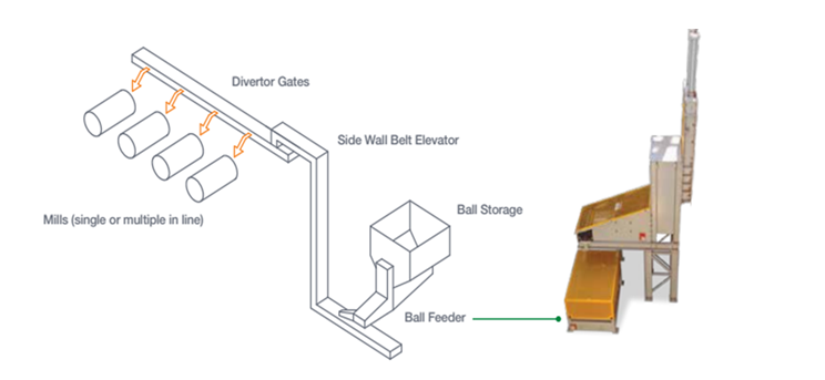
Figure.24. Complete Ball Handling Systems from Delivery to Mill
Separator
The fineness and particle size distribution of the product leaving a cement grinding system is of great importance for the cement quality. The target given for these parameters is achieved by the adjustment of the separator. The separators of the newest generation, rotor cage type separator (high efficiency separator), have several advantages over the previous separator generation, such as
- Less specific energy consumption of the system (less overgrinding);
- increase of system throughput (efficiency);
- possibility of product cooling;
- higher flexibility for adjustments in product fineness;
- more favorable particle size distribution and better product uniformity
CEMENT MILL TEMPERATURE CONTROL
Recipe control and fineness control via adjustments in the feed rate to the mill and separator speed are the main jobs of the cement mill operator as this is the way that cement is produced to conform to the strength specification. That is the primary quality characteristic that the customers of the cement company will be expecting. There is no opportunity to adjust the quality of the cement after the Finish milling section of the cement factory. Around 5% of gypsum for control of the setting time of the cement is added to all types of cement. If no gypsum was present in the cement then the cement would set very quickly and there would not be enough time for mortars or concretes to be compacted and worked in to amould.
To control the setting of the cement there will be target for cement SO3 content that will be set by the chemist. The amount of gypsum ground with the clinker and other components of the cement will be rationed to the total feed to the cement mill to give a constant percentage gypsum addition. Gypsum is calcium sulphate with two molecules of water of crystallization, (CaSO4.2H2O,) and therefore a constant percentage gypsum addition will mean a constant SO3 addition to the cement. The chemist will set the target for cement SO3 content based on the physical Testing results of the cement when it is made into a standard mortar. That target will depend on the typical temperatures experienced and residence time that the cement and gypsum spend in the cement mill. Ball mills for cement grinding are very in efficient Machines and >90% of the electrical energy input from the mill motor is converted into heat as the mill is turned and the media in the mill tumbles and impacts on one-another and the lining plates of the cement mill.
If the clinker that is being ground is fresh from the kiln then it is likely to be at a temperature of 80°C, or higher. The combination of these two heat energy inputs operating a Cement Factory Cement Mill Temperature Control means that temperatures in ball mills for cement grinding can rise to well above 100°C. At these temperatures the gypsum is not stable and progressively loses water of crystallization to first form hemihydrate, then soluble anhydrite and eventually natural anhydrite. These different mineral forms of calcium sulphate dissolve in the mixing water at different rates when the cement is mixed with water to make Mortar or concrete.
For cement setting control it is important that the amount of sulphate dissolving in the mixing water is matched with the reactivity of the cement clinker and particularly the C3A in the cement clinker. The chemist will set the cement SO3 target based on the typical mineral form of the calcium sulphate after it has been ground in the cement mill. It is therefore important that the temperature to which the gypsum is raised and the time spent at that temperature is consistent as this will lead to the gypsum always being in the same mineral form and having the same solubility.
This is why temperature control in cement mills is important. With ball mills for cement grinding the requirement is normally to cool the cement mill to control the temperature and the gypsum dehydration. Ambient air is drawn into and through the mill by an induced draft fan (id fan) to cool the mill. The pressure drop across the mill is monitored to control the volume of air being drawn through the mill. However, the amount of air that can be drawn through the mill is limited as the velocity of that air should not exceed 2.5m/s. If a greater volume is drawn through the mill then the velocity rises and coarse material is pulled out of the mill with the air stream before it has been sufficiently ground. This limitation on the velocity of the air sweeping the mill means that if the diameter of the ball mill is more than ~3.5m then not enough air can be drawn through the mill to adequately cool the mill and control the temperature.
Additional cooling by means of water injection sprays into the mill has to be introduced. The normal arrangement is for the mill exit air temperature to be monitored and controlled to a target of 110~115°C by varying the amount of water that is sprayed into the mill. In large mills water might be sprayed first into the outlet chamber of the mill up a maximum amount and then also into the inlet of the mill if the temperature cannot be controlled by the outlet chamber water injection. The injected water must be vaporized as it is sprayed into the mill and cools the mill by Operating a Cement Factory. Cement Mill Temperature Control evaporative cooling. The heat energy in the mill is absorbed to evaporate the water. To ensure that the water is vaporized the water is injected at high pressure or with compressed air through atomization nozzles. These arrangements have worked well for many years with ball mills for cement finish grinding. Provided that the temperature control in the mill and the residence time of the gypsum in the mill is constant then the gypsum mineral form and solubility is controlled and the setting of the cement controlled. Residence times in ball mills for cement grinding are typically 20 minutes or more
CEMENT PRODUCTION PROCESS
In DMC factory cement production process is operates Clinker and additive raw materials like gypsum and pumice produces Portland cement. These three materials are proportion and then feed into cement mill by belt conveyer. They will ground in a cement mill. However, without additive of pumice; it produces ordinary Portland cement by only proportioning 95% clinker and 5% gypsum. In a cement mill, there is a cylindrical shell lying horizontal which contains steel balls and as it rotates, the crushing action of the balls helps in grinding the clinker to fine powder. The length of the horizontal cylinder is 12.93m and its both chamber diameter is 4.48m.The diameters of the steel ball varies from 20-90mm and have two chambers.
The first chamber has ball diameter 60-90mmwith total weight of 42ton and the second chamber have ball diameter of 20-60mm and with total weight of 112.7ton. The inside part has three kinds of plates. These are armer, liner and diaphragm (serve as sieve) plate. The output of a cement mill is inter into largest separator cyclone, then the fine product separated in to 6-smaller cyclone by air pressure and the coarse one return into cement mill. The fine cement product transferred to silo by using bucket elevator to be packed. The term bag house is applied to large filters containing number of tubular bags mounted in a usually rectangular casing. The dust laden air is drawn through them by suction. The bag house is used to remove dusty particles from discharge of different equipment such as cement mill. In a bag house system discharge gas containing dusty particles is passed through a series of bags made of strong fabrics and return into cement silo storage by using screw conveyer and air slid.
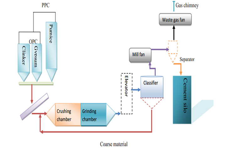
Figure.25. cement production flow
Additive materials hammer crusher and longitudinal storage
Pumice and basalt hammer crusher is used for crushing basalt and pumice. The capacity of hammer crusher is 1000tons/hr.
Parts of hammer crusher;
- Gearbox 4. Motor
- Flywheel 5.Sprocket
- Apron feeder 6. Belt drive
Longitudinal storage of raw materials
This longitudinal storage is used to store additive materials like sandstone, basalt, pumice and gypsum. Capacities of each materials store in horizontal storage are
Sandstone……..6000tons
Basalt……….12000tons
Pumice…….24000tons
Gypsum………..6000tons
Generally longitudinal storage holds 48000tons capacity of additive materials.
Gypsum
It consist of sand, calcareous sand and limestone. It used for setting, but also other of limestone, gypsum influences not only the setting, but also other cement properties such as grind ability sensitivity to storage volume stability and strength, So3 contents 3% or more are required for using gypsum as setting time controller by inter grinding with clinker
Pumice
To increase the quantity of cement, too finer; by decreasing the strength and also decrease the cost
Pumice drying system
The pumice coming from mike has a moisture content varying from 8 to 20 % depending on the season. DMC utilizes rotary dryer which works with hot gas. Before it has to be grounded in the ball mill with other cement materials, the moisture has to be dried about less than five percent, according to the design of the ball mill. However, from the factory past experience, no need of drying if the coming pumice moisture content is less than ten percent. So, in this situation the dryer doesn’t work.
Parts of pumice drier
- Girth gear
- Support
- Gearbox
- Motor
- Pulse jet bag filter
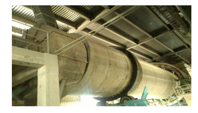
Figure.26. Pumice drier
Major Types of Cement are
- OPC – Ordinary Portland Cement
- PPC – Portland Pozzolana Cement
- PSC – Portland Slag Cement
- SRC – Sulphate Resisting Cement
- HAC – High Alumina Cement
- OWC – Oil Well Cement
- WC – White Cement
Table 8, Types of cement
| Cement | Manufacture | Application |
| Portland cement | ||
| 33 OPC | ||
| 43 OPC | ||
| 53 OPC | Different mineral composition | General purpose work |
| LHC,SRC,RHC | Clinker + Gypsum | |
| MHPC,WC | ||
| PSC | Clinker + GBFS (25-65%) + Gyp. | Used in sulphates bearing soils |
| SSC | Clinker + GBFS (70%) + CaSO4 | Acid resistant, Lin seed oil resists and sea water resistant |
| HAC | High Al. clinker | Rapid strength development(24hr) |
| PPC | Clinker + Pozzolana (15-35%) + Gyp. | Lower shrinkage, heat hydration and alkali resistant Used in mass concert and maraine construction |
| OWC | Reduced C3A clinker and coarse grinding | Used in high pressure and high temperature in sealing water and gas pockets |
| WC | Clinker with Fe2O3<1% and C3A (15-18%) | Architectural purpose and pastel finish |
| Hydro Phobic Cement | Clinker + water repelling agent | |
| Masonry cement | Clinker +Pozzolana materials + Gypsum + air entraining plasticizer | Slow hardening, high workability and high water retentivity Used for masonry mortals for brick, stone and plastering |
Depend on addition of pumice DMC cement factory produce two types of cement
- Ordinary Portland cement (OPC)
Clinker + Gypsum = OPC
- Pozzolana Portland cement (PPC)
Clinker + Pozzolana + Gypsum = PPC
Ordinary Portland cement (without pumice)
- Is now very rarely used, as high strength of cement have become increasing popularly.
- Is the most popular used today on the market
And commonly used in construction work; such as residential, commercial & industrial structures and most pre-casts, pipes, plastering, flooring & others nonstructural applications
- It has high quality used for constriction industry such as bridge, dams etc.
Pozzolana Portland cement (with pumice)
It has relatively low quality used for ground house. Additive pumice and gypsum to clinker results is called PPC. This type of cement has low strength relative to OPC and it is the usual Dmc product. A pozzolanic material is essentially a siliceous or aluminous material which while in itself possessing no cementitious properties, which will, in finely divided form and in the presence of water, react with calcium hydroxide, liberated in the hydration process, at ordinary temperature, to form compounds possessing cementitious properties. The pozzolanic materials generally used for manufacture of PPC are calcined sandstone or basalt. The pozzolanic action is shown below:
Calcium hydroxide + Pozzolana + water —-> C – S – H (gel)
Portland Pozzolana cement produces less heat of hydration and offers greater resistance to the attack of aggressive waters than ordinary Portland cement. Moreover, it reduces the leaching of calcium hydroxide when used in hydraulic structures. It is particularly useful in marine and hydraulic construction and other mass concrete constructions. Uses:
- For hydraulic structures;
- For mass concrete structures like dam, bridge piers and thick foundation;
- For marine structures;
- For sewers and sewage disposal works.
The following table indicates the quantity of additives added into clinker in cement product specific at
Table 9, Types of cement and their composition
| Types of Cement | Raw materials | Content in percent (%) |
| OPC | Clinker | 95% |
| Gypsum | 5% | |
| PPC | Clinker | 67% |
| Pumice | 28% | |
| Gypsum | 5% |
CEMENT QUALITY CONTROL
Portland cements are commonly characterized by their physical properties for quality control purposes. Their physical properties can be used to classify and compare Portland cements. The challenge in physical property characterization is to develop physical tests.
Due to conformity to the cement and raw mill quality requirement should be verified and monitored by quality control.
- for cement mill by:-
- setting time depend on additive of gypsum
- by test soundness
- by the composition required to ensure high sulphate resistance
- by test compressive strength and flexure
- by insoluble residue and content of sulphate(SO3)
SETTING TIME
Setting refers to a change from a fluid to a rigid stage Cement paste setting time is affected by a number of items including: cement fineness, water-cement ratio, chemical content (especially gypsum content) and admixtures. Setting tests are used to characterize how a particular cement paste sets. For construction purposes, the initial set must not be too soon and the final set must not be too late.
Cement + water → cement paste → lose its plasticity gradually→ when it lose its plasticity completely → setting occurs. There are four main stages during setting time
First stage
- Takes only few minutes after the addition of water to the cement
- The rate of heat generation is high, due to wetting of cement particles with water, and the beginning of hydrolysis and reaction of the cement compounds. After that the rate decreases to relatively low value.
Second stage (dormant period)
- Takes 1-4 hours with relatively low speed
- The initial layer of the hydration begins slowly to build on the cement particles.
- Bleeding and sedimentation appears at this period.
Third stage
- Heat of hydration begins to rise again due to the dissolution of the weak gel layer formed in the beginning (first) on the surface of C3S crystals – so the water able to surround the particles surfaces again – and forming gel of calcium silicates with enough amount to increase setting.
- The activity reach its peak after about 6 hours for cement paste, with standard consistency, and might be late for paste with higher w/c ratio.
At the end of the stage, the paste reaches the final setting stage.
Fourth stage
Hardening and gain of strength
Vicat apparatus
Use to measure the setting time for cement paste.
Initial setting time – refers to the beginning of the cement paste setting.
Final setting time – refers to the beginning of hardening and gain of strength.
- Iraqi Standard Specification No. 5 limits:
- Initial setting time not less than 45 minutes
- Final setting time not more than 10 hours
Factors affecting the setting time
- Water/cement (w/c) ratio – The setting time of cement increase with the increase of w/c ratio.
- Temperature and relative humidity – The setting time of cement decreases with a rise in temperature and decrease of relative humidity.
- Fineness of cement – The setting time of cement decreases with a rise in fineness of cement.
- Chemical composition
Flash setting- It is abnormal premature stiffening of cement within a few minutes of mixing with water – It differs from flash set in that:
- No appreciable heat is evolved.
- Remixing the cement paste without addition of water restores plasticity of the paste until it sets in the normal manner and without a loss of strength.
Occurs when there is no gypsum added or exhausting the gypsum (added with little amount). So C3A reacts with water causing liberation high amount of heat causing rapid setting of cement, and leading to form porous microstructure that the product of hydration of the other compounds precipitate through unlike the normal (ordinary) setting that have much lower porosity microstructure.
Causes of false setting
Dehydration of gypsum
When inter ground with too hot a clinker formed: Hemihydrates (CaSO4. 0.5H2O) – when temperature between 100- 190o C or anhydrite (CaSO4) when temperature > 190 o C And when the cement is mixed with water these hydrate to form gypsum, with a result stiffening of the paste.
Reaction of alkalis of the cement-
During bad storage – alkalis in the cement react with CO2 (in the atmosphere) to form alkali carbonates, which they react with Ca (OH) 2 liberated by the hydrolysis of C3S to form CaCO3. This precipitates and induces a rigidity of the paste.
K2O or Na2O + CO2 → K2O3 or Na2CO3
K2CO3 or Na2CO3+ Ca (OH) 2 → CaCO3
Activation of C3S subjected to wet atmosphere
During bad storage water is adsorbed on the grains of cement (the water stick on their surfaces) and activates them and these activated surfaces can combine Very rapidly with more water during mixing: this rapid hydration would produce false set.
Fineness of cement
Fineness or particle size of Portland cement affects Hydration rate and thus the rate of strength gain. The smaller the particle size, the greater the surface area-to-volume ratio, and thus, the more area available for water-cement interaction per unit volume the effects of greater fineness on strength are
Generally seen during the first seven days when the cement particles are coarser, hydration starts on the surface of the particles. So the coarser particles may not be completely hydrated. This causes low strength and low durability. For a rapid development of strength a high fineness is necessary. The last steps in the manufacture of cement are the grinding of clinker mixed with gypsum.
It reduce the water layer separate one the mixture surface due to bleeding On the other hand the fineness of cement has disadvantages:
- Increasing the cost of grinding with increase fineness
- Storage difficulties, due to the finer the cement the more rapidly deteriorates on exposure to the atmosphere. Because the increasing of surface area that exposed to atmosphere.
- Increasing the cement fineness means increasing in drying shrinkage.
Test for Fineness
There are various methods for determining the fineness of cement particles. Fineness of cement is tested in two ways
Sieve Method
It is the classical method to measure the cement fineness, in which the residue percent of cement on sieve No.170 (90 µm) according to BS (British Standard) shall not exceed 10% for ordinary Portland cement. According to American Standards ASTM the residue percentage on sieve No.200 (74µm) shall not exceed 22%
Blaine Method
The Blaine air-permeability method is the most commonly used method. In the Blaine air- permeability method, given volume of air is passed through a prepared sample of definite density. The number and size of the pores in a sample of given density is a function of the particles and their size distribution and determines the rate of air flow through the sample.
By determination of specific surface (total surface area of all the particles in one gram of cement by air-permeability apparatus).cm2/gm. or m2/kg, the quality of cement is measured by the surface area or the Blaine index. The unit of the Blaine index is m2/kg, and this index is determined by the Blaine air permeability test. The surface area of the cement powder depends on size distribution of cement particles; smaller particles have larger surface area The cement clinker grinding circuit reduces the feed from 80% passing size between 10 and 20 mm to 100% passing 90 microns. The size reduction takes place in a two compartment tube mill; the first compartment of the mill is shorter than the second Compartment. The coarse clinker is ground in the first compartment where larger balls (80, 60, 50 mm) are used and the fine grinding is done in the second compartment where smaller balls (below 25 mm) are used.
A diaphragm separates the two compartments and allows only particles below a certain size to pass to the second compartment. Ground material exits the mill through the discharge grate which prevents grinding balls from leaving the mill. A proportion of material, mostly fines, is “air-swept” out of the mill. The final product is the fine fraction of the air classifier and the coarse fraction returns to the mill.
Specific surface area (cm2/g) =K t
K=factor in (g/cm3.s)
t=in second
Example DMC In lab for OPC W=2.8305gm
K=37.88
For PPC W=2.7288gm
K=39.25
t=2.28min=2min+28second=120second+28second=148second
Example for PPC
Blaine Area =K t
=39.25
=477.49686cm2/g
Blaine for OPC, 3500 with filler and 3300 without filler
PPC 3800 with filler
Pumice 800
Consistency of standard paste
It’s defined as the percentage by mass of water to cement required producing cement paste of desired consistency. It is used in the determination of the initial and final setting times and soundness of cement. The consistency is measured by the Vicat apparatus, and it is defined as that consistency which will permit a Vicat plunger having 10 mm diameter to penetrate the paste to a point (5±1 mm) from the bottom of the mold.
Soundness test
The testing of soundness of cement to ensure that the cement does not show any appreciable subsequent expansion is of prime importance which could result in a disruption of the hardened cement paste (namely the cement paste, once it has set, does not undergo a large change in volume).
Factors affecting the soundness of cement
- Mg content of raw materials-use raw material with less content of Mg
- Chemical composition of clinker:-high liquid clinker less will free particle
- Fineness of raw meal i.e. more finely pulverized (to reduce) raw meal reacts better
- Burning of the clinker: – as burning temperature in kiln increase free limestone decrease
- Cooling the clinker
- Fineness of the cement i.e. when the finesse is great there will be less expansion.
Note: – The main purpose of the soundness test is to assess the possible risk of late expansion due to hydration of uncombined CaO and /or MgO. Is ability hardened pasted to maintain volume after setting .Expansion for all Portland blended and hydraulic cements < 0.80%
The unsoundness in cement is due to
Lack of a volume stability is caused by high content MgO and caused by hard burned CaO or MgO
- The delayed or slow hydration
- The presence of excess of lime than that could be combined in kiln.
- Excessive proportion of magnesium
- Excessive proportion of sulphates
Because unsoundness of cement is not apparent until after a period of months of years, therefore accelerated tests are required to detect the unsoundness of cement. The cement soundness could be tested by two methods:
Autoclave Test, ASTM C 151-09
Le Chatelier Test, BS EN 196-3:2005
Cement strength
Whatever type of cement is being produced it will be being produced to a strength specification, for PPC 32.5, and for 42.5. This strength specification is the strength which a standard mortar made with the cement will attain 28 days after the cement is mixed with sand and water to produce the mortar. Different recipes will allow these strengths to be attained and the cement chemist will set the recipes. Attaining the strength with the particular recipe is then a question of grinding the cement finely enough. Usually the cement must be ground to a surface area target. With blended cements with multiple components sieve residue targets are sometimes used in addition to, or instead of surface area targets. This can also be best if outside stored clinker is being ground as pre hydration of that clinker will create some “false surface” in the cement mill.
The compressive strength of hardened cement is the most important of all the properties for structural use. The strength of mortar or concrete depends on the cohesion of the cement paste, and its adhesion to the aggregate particles and to certain extends on the strength of the aggregate itself. The last factor is not considered at this stage, and is eliminated in tests on the quality of cement by the use of standard aggregates.
Strength tests are not made on a neat cement paste because of difficulties of molding and testing with a consequent large variability of test results. Cement sand mortar and, some cases, concrete of prescribed proportions and made with specific materials under strictly controlled conditions, are used for the purpose of determining the strength of cement. There are several forms of strength tests:
- Direct compression
- Direct tension
- Flexure
Direct tension strength and flexure strength of concrete are generally of lesser interest than compressive strength. Nowadays the compressive strength of cement that considered being crucial.
Mixed in suitable proportions of cement and water
- Cement paste = water + cement
- Mortar = water +cement +sand
- Concrete = water +cement +sand +gravel
Cement paste can only be used on concrete surfaces of for repairing cracks but as a special case it is also often used as a reinforcing agent for strengthening base rock in tunnels & dams. Mortar is used to plaster walls & floors of building and as an adhesive & filler for bricks, blocks & tiles N.B. cement strength is not indicated by cement paste strength, but by the strength of mortar prepared
Cement color control
Iron oxide, which is present in some of the raw materials used in the manufacture of cement, is
Responsible for the grey color of OPC, White Portland cement is made from raw materials containing little or no iron or manganese, the substances that give conventional cement its gray color. So the secret of the White cement is raw material. Apart from that only whitest chalk is used together with light colored sand in production of white cement. White cement production needs usually 40% higher energy than the normal grey cement and the difference between ordinary cement and while cements are as follows: The amount of chromium, manganese, iron compounds is significantly less in white cement in comparison to gray cement Production. White cement consumes significantly more energy in comparison to gray cement Kindly note that the setting behavior and strength development of white cement is almost equivalent to grey cement. Further, Gypsum is used in the making of both white and ordinary grey cement.
Cement silo
Cement silos are used to store cement elevated by buckets elevator chain and pour in it. There three cement silos used in DMC factory, each of them have 10000tons storing capacity. Cement silos uses compressors and root blowers for: blending and aeration in cement silo will be transported by bucket elevator and air slides by pneumatic conveyor.
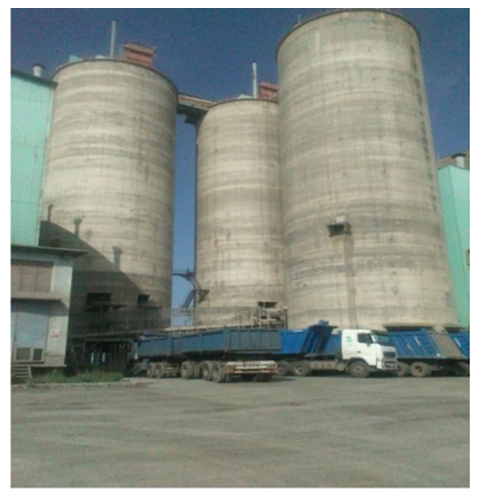
Figure.27. cement silos
PACKING
The cement discharged from silo is transported to air slides and bucket elevator and discharge into a screen which is located above the receiving hopper of the packing machines to separate foreign matters. The cement is packed with the help of a rotary packer and finally dispatched to the market
Packaging of cement
Cement extracted from the storage silos is fed to the packing machines from where packing in sacks, bags and in bulk is done. The cement silos should have a blower extraction system to reduce power consumption. Packing machines are of two types such as stationary and rotary packer. The packing line of products in powder form is equipped with different element or machine. Power consumption for packing system are 2-2.2KWh/t and capacity 100-120t/h.
The principal elements of the packing line are
- Vibrating screen
- Feed hopper
- Rotary feeders
- Discharging belt
Flow of material in the packing plant
The flow of material rises from the chain bucket elevator to reach the vibrating screen. This vibrating screen is equipped with control systems (called sensor) placed inside the hopper, then the flow of material passes through the rotary vane feeder equipped with alternate gear to adjust the level of material in the packer machine. The flow of material is then directed to the spouts.
Most parts of the packer in the bag, where as a very small of scraps, in form of dust and overflows. The dust is sucked up and collected by means of a sucked chute in the lower hopper and rejected by separator.
The dust is gathered by a screw conveyor and led back into the conveying cycle
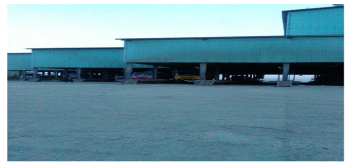
Figure.28. packing plant
Rotor packer machine
Is rotating packing machine designed for packing loose, bulk material at the capacity range of up to 120tons/hr. Cement filling system with root blower are for bagging of free flowing. There are six rotor machines in DMC
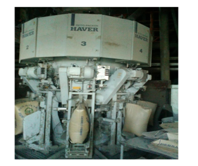
Figure.29.Rotor packer machine
Basically the Rotor packer uses different types of sensors:
- position sensors
- proximity sensors
- level sensors and
- Weight sensors are found to be work together to put out the final products.
BULK LOADING
Cement is shipped through bulk (powder form) directly from the silos, by marine these are least expensive and easiest form of transport, & 80% of cement is shipped by this method. Bulk is shipped to terminals for an on ward distribution to the customer
Uses and Application of cement
Cement has a wider application in many parts and is a basic thing in our live which is widely used in construction of public buildings, homes, roads, industrial plants, reactors, dams, bridges, and many other structures and are the cements used by the Romans, and can be found in Roman structures still standing (e.g. the Pantheon in Rome). They develop strength slowly, but their ultimate strength can be very high.
Conclusion
In generally Derba cement factory is one of the biggest cement factories in Ethiopia. The factory changes its production process from wet process to dry process and promote production scale and its quality. The cement production depends on the adopted cement production process.
The factory use modernized dust recycle device which reduce environmental pollution. Totally cement production of Derba cement factory start from quarry to cement packing plant. The cement production capacity of Derba cement factory is 7000tons/day
Critical Observation and Recommendation
Observation 1; Clinker wastage
Recommendation
- Constructing of additional clinker storage to reduce power consumption during grinding of clinker; to maintain cement strength and to be profitable.
Observation 2; Dust emitted out of off spec silo to environment
Recommendation
- Install cyclone with screw conveyor is important
Observation 3; There is a problem of online document. Lack of sufficient and relevant information compared to the top cement companies of the country.
Recommendation
- Working with the IT department, it is very important for DMC to work hard towards creating an affirmative impression about the company to the viewers of their website from all around the world by loading any information related to this plant.
Observation 4; There is a problem of Miscommunication and misinterpretation of messages exchanged between an employee and the operator at times, messages were interpreted incorrectly and some confusion took place due to the inability to understand the speech of one another over the communication. Because most operating system is held by china operator and also operating system language was Chinese
Recommendation
- To deal with this situation, we would suggest to DMC, first increase the number of skilled operators in this department immediately. Then, substitute china staff by local staffs.
- Absence of recognition programs for the employees during our period of internship in DMC I noticed that although the working environment of the company is very pleasant and the employees are satisfied with their pay and the facilities that the company provides for them, however I observed that there was an absence of recognition programs for the employees. It is very important for the employer of an organization to recognize the efforts of an employee and appreciate his work. This not only helps to improve the relationship between an employer and an employee but it also helps an employee to understand the pace of his work compared to that of his co-workers. In this way the employees will also be more satisfied with their jobs and ultimately, it will be beneficial for the organization in terms of high productivity. Skills and performance based performance appraisal programs should also be introduced in the organization.
Observation 5; false air infiltration – cold air entering the system via kiln hood, burner opening and casing. It either dilutes secondary air thus reducing recuperated heat or adds load to the waste air system of grate coolers and increase load on ID fan.
Recommendation
- Close the casing by welding
Observation 6; dust emitted in stack installed with ESP
Recommendation
- Install additional cyclone for the dust emitted from pumice drier which can decrease the load on ESP.
Observation 7; the standard sandstone used in laboratory is imported from china.
Recommendation
- For ease compatibility of cement with sand of Ethiopia, we suggest that DMC laboratory must use local standard sand for checking of its strength and to save import cost.
Observation 8; There is a problem of plant installation for using an alternative fuel.
Recommendation
In order to be more profitable, DMC should use at least 25% of alternative fuel. Thus, so as to do this the plant needs some modification and installation.
Its simply superb definitions cant find elsewhere comprehensively in one nut shell
Nice blog about the cement manufacturing process. I think your blog very helpful for more people. Thanks for sharing the information.
Excellent compilation of information on Cement – just very best , It is for all – Learners & beginners/ in depth information seekers/ Researchers and Industry experts.
Deserve all credit , appreciation and Thanks for presenting such a useful work to researchers in the field.
yes .you r right
its really helpful or needful all of us whose are interest.TO BEYONG integrated knowledge can be obtained .
Thankyou
Hello, in this article, cyclone design figure is not visible, kindly let me know what should be the distance of meal pipe from cyclone roof.