Cement kiln main burner by Juan Ortega
CLICK HERE NOW TO DOWNLOAD 25 MOST IMPORTANT BOOK EVER MADE IN CEMENT INDUSTRY & EXCEL SHEETS FOR OPERATION CALCULATIONS.
The cement industry is a large consumer of thermal energy. In this sense, it is very important to build cement plants with low thermal consumption using fuels rationally. The objective of the combustion process in a cement kiln is to convert the latent heat of the fuels into free heat and transfer this heat to the raw materials in order to sinter them into Clinker.
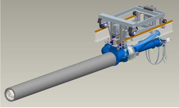
The equipment that is used to feed the kiln system with fuel for the process of burning and generating heat is called “main burner”, constituting one of the most critical components of the kiln system.


In recent decades, the burner has been recognized as an essential part of the clinkerization process, giving due importance to its project. However, even today, sometimes the burner is not considered an important part of the kiln system when its most important function is neglected: to generate a stable flame and optimize the kiln operation.

From the point of view of the process, a modern burner used in the heating of the burning zone of a cement rotary kiln must meet the following needs:
1. The burner must be capable of burning natural gas, fuel oil, coal or petcoke or any mixture of these fuels while ensuring complete combustion, that is, it must use minimum excess air, as well as minimizing the formations of CO and NOX
2. The burner must also be competent to produce a short, narrow, radiant flame that is a fundamental prerequisite for good heat transfer in the kiln sintering zone.
3. The flame due to its format and heat transfer should lead to the formation of a dense and stable coating on the burning area, as well as to aid the Clinker nodulation process with low dust content and mineral formation correctly crystallized.
4. The burner should use the minimum possible primary air because in principle this is a false air that will only increase the thermal consumption of the kiln.
It is necessary that there is an adequate mixture of air and fuel so that there is a correct chemical reaction. It is also important to know the different channels that make up the system to blow air and fuel into the burner. There are control parameters that are necessary to comply with and respect; These are called “moment of flame”, specific impulse and swirl.

With respect to the parts of a burner and its control parameters, they will be subject to another article.
What is the main heat instrument of the cement kiln? What are their characteristics? How does it work?
CLICK HERE NOW TO DOWNLOAD 25 MOST IMPORTANT BOOK EVER MADE IN CEMENT INDUSTRY & EXCEL SHEETS FOR OPERATION CALCULATIONS.
When Sir Isaac Newton (1642-1727) published his masterly work Mathematical Principles of Natural Philosophy, in 1687, he also demonstrated, in this work, the Law of Motion, commonly called “Newton’s Second Law”
According to this law, if we apply a known mass (m), initially at rest, a constant force (F) over a period of time Δt, the object moves with a speed variation Δv, that is, F * Δt = m * Δv
According to Newton, in order to obtain the product F * Δt, a product called a force impulse, the variation m * Δv, called the amount of movement, must be proportional to the mass that is being accelerated.
The amount of movement is also a vital parameter in the quality of a flame formed in the combustion process. Usually the combustion process technicians refer to the amount of movement in a flame as the moment of flame, expressed as the percentage of primary air (instead of primary air mass) multiplied by the velocity of insufflated primary air.
This speed is measured at the burner nozzle. In practice the moment of flame is determined through the expression:
Moment = Lp * v (in% * m / s)
Where Lp represents the percentage of primary air (relative to the minimum stoichiometric amount of air) and v the injection rate in the burner nozzle.
Consequently to maintain the same flame moment when the speed is doubled, the percentage of primary air must be halved.
The burner nozzle project is essential both to achieve the best possible flame moment depending on the fuel used and to produce a flame with shape and length suitable for the combustion environment.

Low flame moment High flame moment
That explains why the moment of the burners is the parameter that determines the shape of the flame. A low moment means that the fuel will simply be injected into the combustion chamber. If the flame moment is less than desired, the resulting flame will be long and weak, and can generate CO production.
In addition, this divergent feed of fuel and primary air produces higher temperatures in the combustion chamber. In the case of the cement kiln, the burning area is covered by refractory bricks and a protective coating that can be quickly destroyed if there is direct contact with the flame produced at a very low moment.
On the other hand, a high flame moment promotes friction at the border between the jet and its surroundings, the secondary air is accelerated and sucked for the flame due to the high speed of the jet.
Experience has shown that the formation of a strong, stable, short, narrow flame requires a minimum moment, depending on the type of fuel used, be it: fuel oil, mineral coal, petcoke.
This means that, for the same flame power, the higher the injection speed, the better the degree of circulation and the lower the amount of primary air. This also means that a high moment represents a faster and more intense mixture, consequently, a shorter and hotter flame.
In modern burners, injection rates are usually very high, approaching or matching the sonic speed under prevailing physical conditions, which requires considerable pressure in the mouthpiece. Thus, to reach speeds around 340m / s, blowers capable of developing 800mbar pressures must be used.
The speed of a burner nozzle must be determined by means of field measurements. It can also be calculated with reasonable accuracy through the static pressure Ps (mmCA) measured before the nozzle such as:
v = 4 * V Ps (m / s)
What about the other control parameters?
What is the Specific Impulse?
What is the Swirl?
We will see it in an upcoming article.
I don’t like to speak in extremely technical terms, but sometimes it becomes necessary. In order to control the quality of the flame in the burner, it is necessary to take care of the “Flame Moment” of two other control parameters.
Specific Impulse
Another of the control parameters of the main burner is: Specific Impulse.

This has a concept similar to the “Flame Moment”, but it is calculated through the product of the mass flow rate of the primary air by the speed of that air in the burner nozzle. It expresses the effect of flame stabilization due to a more energetic mixture between the fuel and the oxidant. The calculation is performed separately for each of the constituent airs of the primary air.

Where:
I = Relative impulse of each of the airs that make up the primary air – axial, tangential, transport and central.
Qt = Mass flow rate of each of the airs that make up the primary air – axial, tangential, transport and central (kg/s) – calculated according to the measurement of gas flow rate.
Vax = Axial speed of each of the airs that make up the primary air – axial, tangential, transport and central (m/s).
The calculation of the velocity of each of the components of the primary air must be carried out as explained during the evaluation of the flame moment. It is important to highlight that the tangential air enters the oven with a certain tormentation due to the presence of a slight angular displacement that gives the air the appearance of a rose in the burner’s mouth. Then he has two components, one being axial and the other radial.
Since it is only possible to measure the total velocity, the axial component of that velocity must be calculated. Other airs only have the axial component.


Vt = Total tangential air velocity
Vax = Axial velocity of the tangential air
Vtg = Tangential velocity of the tangential air
Ө = Angular offset
The total relative impulse will then be the sum of the relative impulse of each of the components, considering the axial component of the tangential air.

Where:
Itotal = Total impulse of primary air
In order to better evaluate the flame, it would be useful to use the so-called “Specific Impulse”, which consists of a dimensionless number calculated from the ratio between the relative impulse of the primary air and the relative impulse of the secondary air.
That number expresses the balance between the effect of primary air in the formation of a rigid flame and the effect of secondary air to break that stiffness.
However, the determination of the relative impulse of the secondary air is difficult to evaluate because to calculate it it is necessary to use the temperature of the secondary air, which is only obtained through a balance in the cooler.
Then, instead of using the relative impulse of the secondary air, the thermal power of the burner is used, since it is proportional to the flow rate of the secondary air, this because the more fuel we use, the more air will be needed to effect the combustion.

Where:
Iesp = Specific impulse [N.h / GJ]
Itotal = Total impulse of primary air [N]
Pot = Burner thermal power [GJ / h]

Where:
Q comb = Mass flow rate of fuel in the combustion zone
PCI = Lower calorific value of fuel [GJ / kg]
Swirl
The third control parameter of the main burner is the Swirl, parallel to the specific impulse, the Swirl or rotational impulse is calculated, which represents the amount of movement that the burner imposes on the flame to cause its rotation. It is calculated through the following equations:

Where:
Irot = Rotational impulse [N.m]
Qradial = Tangential air mass flow rate [kg / s]
Vtangential = total tangential air velocity [m / s]
Ө = Angular offset
Rg = Rotation radius, relationship between the external and internal radii of the angular displacement [m]

Where:
R1 = Internal radius of angular displacement
R2 = External radius of angular displacement
Ө = Angular offset
The swirl is a relationship between the rotational impulse and the total relative impulse of the burner, it represents the opening or width of the flame.

Where:
Sw = Swirl [dimensionless]
Irot = Rotational impulse [N.m]
Itotal = Total relative impulse [N]

Keeping these parameters correctly adjusted allows a stable, strong and precise flame, the positive results are qualitative and quantitative. The optimization area professionals can help you with this adjustment. If you need specific help, hire a specialist in combustion and burners.
(For calculation purposes, the references of measures used in this article are those of “International Measurement System”)
CLICK HERE NOW TO DOWNLOAD 25 MOST IMPORTANT BOOK EVER MADE IN CEMENT INDUSTRY & EXCEL SHEETS FOR OPERATION CALCULATIONS.