Contents
cement kiln alignment Seminar
Alignment Principles
Kiln Alignment
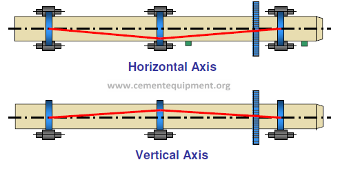
A kiln is considered aligned when the
center of rotation of the kiln shell at
every support lies on a straight line.
Note that a kiln with only two supports
is always aligned, as there is always a
straight line between two points.
Two Support Kiln
A kiln can be misaligned in the horizontal or in the vertical plane.
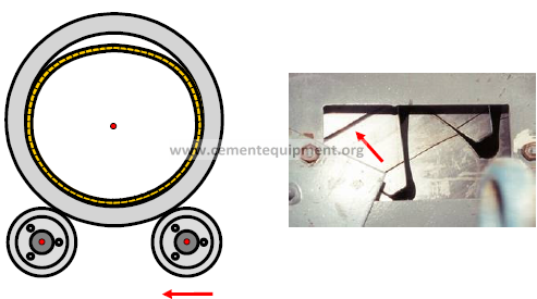
Consequences of Misalignment
Misalignment changes the loading on the
kiln supports and causes overstressing of
the shell and supports.
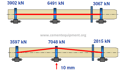
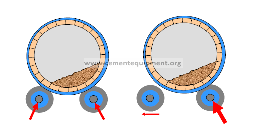
Misalignment can result in all
of the load being
concentrated on one roller.
Internal Alignment
Internal alignment is normally used when
assembling a new kiln. A line of sight is shot
through batter boards marking the kiln centers at
the shell section ends and at the tire locations.
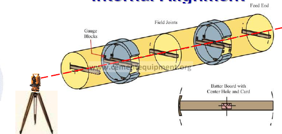
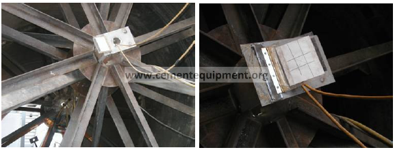
New kiln sections usually have steel spider
bracing with precisely marked centers. If
not, wooden batter boards can be prepared
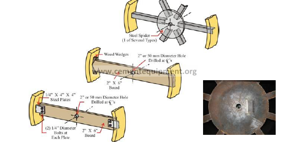
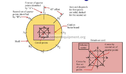
The kiln shell’s center is found by scribing four
arcs on a target card tacked onto the batter board.
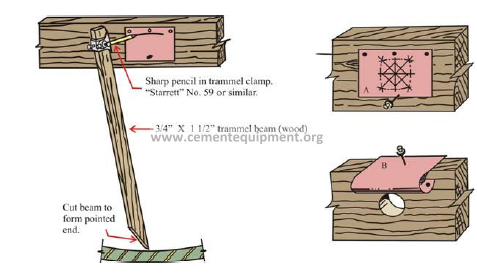
Drawing diagonals at the arcs’
intersections will locate the center.
Removable targets with marked shell centers are
placed at each tire center and shell end. The
theodolite’s line of sight is marked on the target and
the offset is measured.
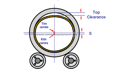
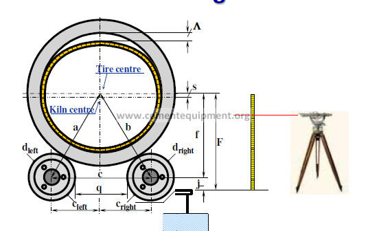
Note that if there is any top clearance present, the tire
center is not the same as the kiln center. Alignment
calculations must take hot running clearance into account.
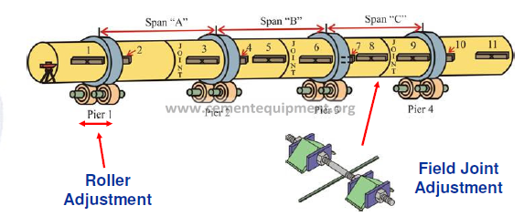
Correcting Misalignment
After measurements are taken the kiln is
aligned by adjusting rollers and field joints.
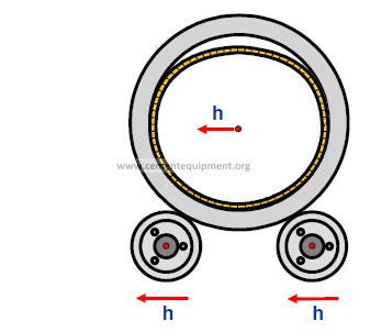
Moving both rollers horizontally will move
the kiln center by the same amount.
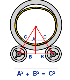
Roller adjustments to correct vertical alignment can
be calculated from the relationship of right triangles.
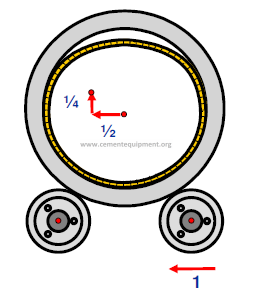
Moving one roller horizontally will move the kiln
center horizontally by half and vertically by one
quarter (approximately) of the distance.
Caution! Moving a roller on the piers
immediately uphill and downhill from the
kiln gear will affect the gear alignment.
Hot Kiln Alignment
Measurements and corrections can
be completed while the kiln is
operating.
The data collected indicates the real
conditions as the kiln is operating.
Alignment errors can be corrected
immediately or during a planned kiln
outage.
-Mechanical Hot Kiln Survey Method
-Laser Kiln Survey (LKS) Method
Both methods utilize a variety of
measured data to determine kilns axis:
Diameter of support rollers and live rings
using electro-mechanical instrument.
Temperature of the support rollers, live
rings and kiln shell.
Creep and clearance between the kiln shell
support pads and live rings.
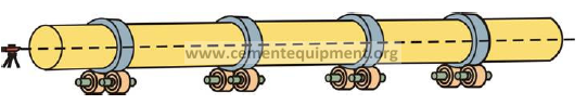
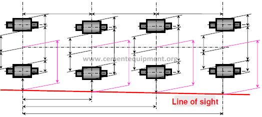
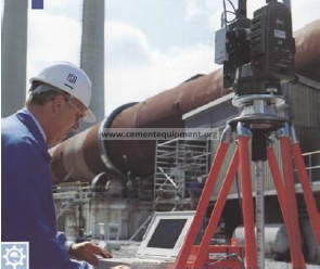
Mechanical Alignment
Using a theodolite to establish a line of sight
along the kiln, the horizontal distances from the
line of sight to each support roller is measured.
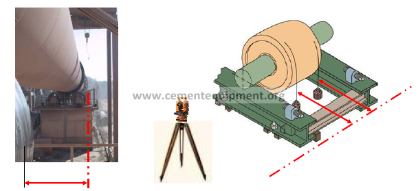
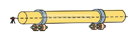
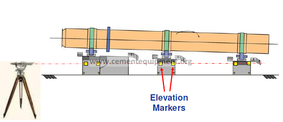
Using an optical level the elevations of
the bearing base frames are determined.
Elevation markers on kiln piers should
be checked to see if a kiln pier has sunk.
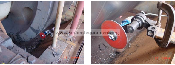
Roller and Tire Circumference
Using a precision measuring wheel and
tachometer the circumference of the roller
and tire are measured.
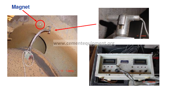
A magnet and magnetic sensor record
start/stop positions. Circumference is read
on the digital readout to 0.1 mm accuracy.
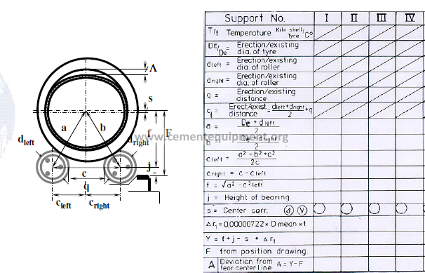
Mechanical Alignment
Using the measurements, and knowing the distance
between supports, a kiln centerline can be constructed
which best fits the existing roller positions.
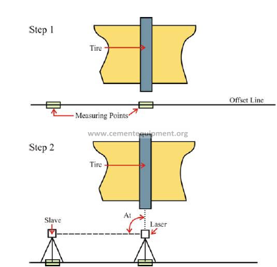
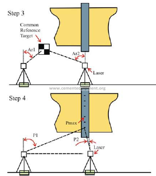
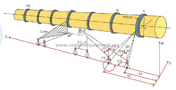
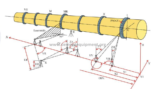
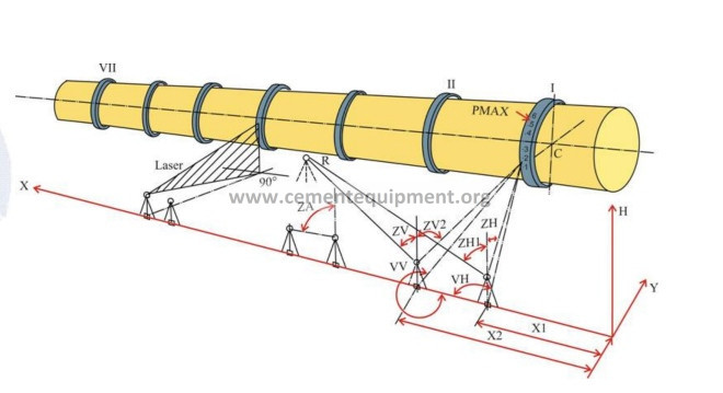
Laser Kiln Survey
Tire elevation and location can be determined
utilizing a laser theodolite from ground level.
Kiln Center Tolerances
Horizontal Plane ± 1.5 mm
Vertical Plane ± 2.5 mm
Laser measurement provides the most
accurate method of kiln alignment.