Contents
Basics of mineral resources for cement production

To Download Everything About Cement crushers , Kilns , Vertical mill , Cement mill , … ETC kindly click here now
Preamble
It is said that cement manufacture begins in the quarry (Figure 1.1), which is the commonly used term for opencast mining of minerals and rocks including limestone, the primary raw material for cement produc-tion. Since there is hardly any alternative to using limestone for making cement, it is treated as one among the most essential resources of a coun-try. However, given its importance in the economy of any nation, our understanding of the genesis, occurrence, composition, properties, min-ing, and application of limestone is rather poor. This is because lime-stone has long been regarded as a “common” rock, and past geological studies were limited in scope, focused essentially on mapping deposits, analyzing rocks, and—occasionally—evaluating aquifers and petroleum reservoirs. However, a different set of data and a deeper understanding are needed to make more efficient use of limestone as a cement raw material. Further, there are certain other naturally occurring raw materi-als like limestone that are also used in cement manufacture, although in smaller quantities and only when required, and they include clay, baux-ite, iron ore, sandstone, and so on. These materials are also obtained from opencast mining operations. Hence, a basic knowledge of geology and mining is important for cement chemists, technologists, and plant engineers. Keeping this in view, this chapter presents the fundamentals of geology, chemistry, and the mining of raw materials as relevant to cement production.

FIGURE 1.1 A view of the limestone quarry at Cedar Creek, Virginia, USA.
Characterization of minerals and rocks
Any naturally occurring chemical compound making up a part of the Earth’s crust is called a mineral. Minerals may occur in solid, liquid, or gaseous form. Natural gas is the best example of the occurrence of minerals in a gaseous state. Petroleum, mercury, and water are the com-monest examples of minerals in liquid form. Solid minerals can either be native elements like gold, silver, etc., or compounds like calcium carbonate (calcite), calcium silicate (wollastonite), aluminum silicate hydrate (kaolinite), etc. The last group of solid minerals in the form of simple or complex compounds is of particular relevance for cement manufacture.
Aggregates of such minerals of more or less invariable composition forming independent geological bodies are known as rocks. Depending on their genesis, rocks are classified as igneous, sedimentary, or meta-morphic. Igneous rocks are formed by the cooling of the molten mass, called magma, inside the Earth. Primary igneous rock types include granite, syenite, dunite, gabbro, basalt, diorite, etc. Based on their silica content, these rocks are further classified as acidic (SiO2 > 65%), inter-mediate (SiO2 65–52%), basic (SiO2 52–40%), and ultrabasic (SiO2 < 40%). Amongst the commonly known igneous rocks, granite is acidic and basalt is basic in composition.
Sedimentary rocks are formed by the deposition of the products of weathering of igneous and metamorphic rocks by mechanical, chemical, or organic means from water or air that acts as the carrier of weathering products. Common examples of sedimentary rocks include limestone, sandstone, coal, iron ore, etc. These rocks are the most relevant ones for cement manufacture.
Metamorphic rocks are derived from previously formed rocks of any kind through primarily in-situ action of high pressure and temperature, as well as of chemicals from hot liquids and gases. Quartzite, schist, gneiss, marble, etc. are typical examples of metamorphic rocks.
Minerals and their intrinsic properties
It is common knowledge that the properties of minerals are a function of their chemical composition and system of crystallization. It is possible to have 32 crystal classes belonging to six systems. All these systems and classes are distinguished from one another by their symmetry. The six main systems are shown in Figure 1.2 (2). While discussing the min-eral constituents of different rocks, as well as the properties of different synthetic phases of clinker and cement, reference is often made to the crystal systems to which they belong.
The physical characters of minerals can either be intrinsic or extrin-sic, as illustrated below:
a. Characters depending upon cohesion and elasticity, such as cleav-age, fracture, hardness, elasticity, etc.
b. Specific gravity or density compared with that of water.
c. Characters depending upon light, such as color, luster, transpar-ency, special optical properties, etc.
d. Characters depending upon heat, such as conductivity, change of form, fusibility, etc.
e. Characters depending upon electricity and magnetism.
f. Characters depending upon the action of senses such as taste, odor, feel, etc.
As already mentioned, all the properties of a mineral depend upon the nature of the chemical elements of which it is composed, and perhaps even more upon the way in which their atoms are arranged in the crystal structure. One of the common methods of identifying and characterizing
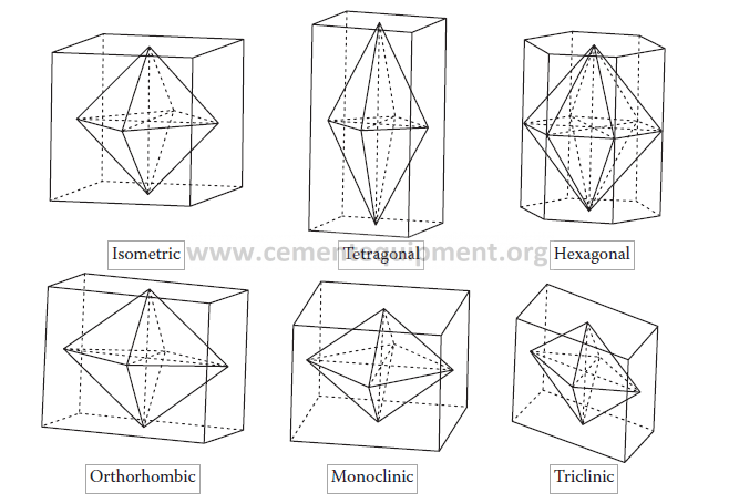
FIGURE 1.2 Different crystal systems based on their symmetries. (E. S. Dana and W. E. Ford: A Textbook of Mineralogy. 1995. Copyright Wiley-VCH Verlag GmbH & Co. KGaA. Reproduced with permission.)
a mineral in hand specimens is to apply the Mohs scale of hardness. In this scale, the degree of hardness is determined by observing the comparative ease or difficulty with which one mineral is scratched by another, or by a file or knife. In minerals, there are all grades of hard-ness, from that of talc, impressible by the fingernail, to that of diamond. For all practical purposes, the Mohs scale of hardness is followed:
1. Talc
2. Gypsum
3. Calcite
4. Fluorite
5. Apatite
6. Orthoclase
7. Quartz
8. Topaz
9. Corundum
10. Diamond
Physical and technological properties of rocks
For example, if the mineral under examination is scratched by a knife-blade as easily as is calcite, its hardness is said to be 3; if less eas-ily than calcite but more easily than fluorite, its hardness is between 3 and 4. It has generally been observed that compounds of heavy metals, such as silver, copper, mercury, lead, etc., are soft. Carbonates, sulfates, phosphates, sulfides, and hydrous salts are neither soft nor hard, whereas oxides and silicates containing aluminum are conspicuously hard.
The general properties of rocks, as expected, depend primarily on their mineral composition and microstructure, that is, their structural and tex-tural features. Texturally, rocks can be friable, where the grains are not interconnected as in sand, pebble, gravel, etc.; or coherent, where water-colloidal bonds hold the particles together through plasticity, such as in clay, loam, bauxite, etc.; or hard, where there are rigid elastic bonds between the mineral particles, as in limestone, granite, gneiss, marble, etc.
Depending on grain size and crystalline characteristics, rocks are classified as shown in Table 1.1.
Table 1.1 Classification of rocks based on grain size

Mining practice and theory utilize all the properties of rocks relating to their mechanics, thermodynamics, and electrodynamics, which are clubbed as physical properties. These are mostly coupled with another set of rock characteristics, known as technological properties, which refer to different conditions of the breaking of rocks under complex states of stressing. Each of the technological properties has narrow lim-its related to the application of certain techniques, machines, or tech-nological media upon the rock. The technological indices reflect on a function not solely of the rock itself but also of the mechanisms acting on them. The physical and technological properties are summarized in Tables 1.2 and 1.3, respectively (3).


The physical and technological properties that have been briefly sum-marized in the above tables influence the geological prospecting and min-ing operations in various ways. The exploration of an ore deposit that is essential for delineation of the ore body demands the knowledge of appar-ent specific gravity, electrical resistance, thermal conductivity, behavior of elastic waves through rocks, magnetic susceptibility, etc. More par-ticularly, operations like geophysical exploration, drilling, blasting, rock breaking, and mineral extraction depend upon the strength properties of rocks, their plasticity, porosity, and fracturing. The size reduction and transportation of rocks involve the knowledge of hardness, crushability, water saturation characteristics, abrasiveness, etc. The physics of rocks are as important as their chemistry in any mineral processing industry.
Nature of limestone occurrence
The term limestone is applied to any calcareous sedimentary rock con-sisting essentially of carbonates. Most limestone deposits are formed in shallow, calm, warm marine water, which provides an environment where organisms capable of forming calcium carbonate shells and skel-etons can easily extract the required ingredients. When these organisms die, their shell and skeletal debris accumulate as sediment and with time consolidate and compact into limestone rock. This kind of limestone is known as biological or organic sedimentary rock. Their organic genesis is often reflected in the rocks by the presence of fossils. Limestone can also form by direct precipitation of calcium carbonate from marine or fresh water and is known as chemical or inorganic sedimentary rock. It has generally been observed that most commercially viable lime-stone deposits were formed by the organic route. Limestone altered by dynamic or contact metamorphism becomes coarsely crystalline and is referred to as “marble” and “crystalline limestone.” It may be of theoret-ical interest that some carbonate bodies are of igneous origin—known as carbonatite—resembling marble, although geochemically much dif-ferent. However, the occurrence of carbonatite is rare and is not impor-tant for cement production.
The distribution of limestone in space and time has been dealt with in (4). It makes up about 10% of the Earth’s total land surface and is found in many countries. At the same time, limestone deposits are encoun-tered in almost in all geological ages, spanning over 600 million years, although rocks of certain periods, such as the Ordovician or Cretaceous periods, show a predominance of carbonates. Build-up of limestone is more abundant between global latitudes of 30° North and 30° South, with such deposits particularly abundant in the Caribbean Sea, the Indian Ocean, the Persian Gulf, and the Gulf of Mexico. China, the USA, Russia, Japan, India, Brazil, Germany, Mexico, and Italy are some of the world’s largest limestone producers. Bands of limestone emerge from the Earth’s surface in often spectacular rocky outcrops and islands. The Swedish island of Gotland, the Niagara Escarpment in Canada and the USA, Notch Peak in Utah, the Ha Long Bay National Park in Vietnam, and the hills around the Lijiang River and Guilin City in China are some examples of such limestone occurrence. The Florida Keys, islands off the south coast of Florida, should also be mentioned in this context, as deposits there are composed of unusually textured “oolitic” limestone, described later in this chapter. So far as limestone quarries are con-cerned, the world’s largest is reported to be at the Michigan Limestone and Chemical Company in Roger’s City, Michigan, USA. Huge quarries are also found in Europe, such as the quarry system of Mount Saint Peter in Belgium and the Netherlands, which extends to over 100 kilometers.
Global production of limestone was estimated at 4.5 billion tons by Oates in 1998 (5). Since then, in about fifteen years, cement produc-tion itself has exceeded 4 billion metric tons. Hence, it would not be wrong to consider that the present consumption of limestone primarily for making cement and construction aggregates and also for other less voluminous industrial applications might be close to 6 billion tons. The USA consumes between 5 and 10% of the global production of industrial limestone and its production was 1.3 billion metric tons when calculated roughly a decade ago (6). For China, the world’s largest producer of cement, specific data on limestone production were not readily available, but Chinese statistics indicate that the operating revenues from lime-stone and gypsum mining in 2016 were close to US$ 15 billion. So far as India, the second-largest producer of cement, is concerned, the mineral production statistics of the Indian Bureau of Mines (7), the apex body dealing with mines and minerals in the country, showed that the pro-duction of limestone from April, 2014 to March, 2015 was 293 million metric tons, although the total cement-grade limestone resources in the country were about 125 billion metric tons, spread across states such as Karnataka (28%), Andhra Pradesh (20%), Rajasthan (12%), Gujrat (11%), Meghalaya (9%), and Chattisgarh (5%). The actual production of cement-grade limestone in different states, of course, follows the demand pattern of the cement industry, which has been showing an increasing trend. It is tentatively presumed that about 1.5 tons of limestone are required to produce 1 ton of plain Portland cement, and about 0.8 tons of limestone for every ton of blended cement. Thus, for the present capacity of about 425 million metric tons per year—composed in India of approximately 25% plain Portland cement and 75% blended cements—the total annual limestone demand is estimated at about 580 million metric tons on hun-dred percent utilization of cement production capacity.
Assessment of limestone deposits
Occurrence of a mineral is an indication of mineralization that is wor-thy of further investigation, although it does not imply any measure of volume or grade. However, before a cement plant is conceived, an ade-quate quantity of limestone should be identified and explored, based on the geological reports of mineral occurrence. There is no shortcut to exploration or prospecting, which are the terms used in a more-or-less interchangeable manner, defined as a systematic process of searching for a mineral deposit by narrowing down the areas of promising min-eral exploitation potential. Only after completing the necessary quantum of prospecting can a mineable deposit be defined with certainty and a high level of confidence. An exploration program is a carefully designed activity with a view to obtaining optimum information and data for deci-sion making with minimum investment. Programs generally consist of the following steps—not necessarily in the same order, and, of course, not including statutory requirements, which are outside the purview of the present discussions:
• Reconnaissance
• Surveying
• Geological mapping
• Trenching and pit sinking
• Core drilling
• Preparation of plans and sections
• Exploratory mining
• Sampling and analysis
• Preparation of grade control maps, mine layout plans and sections
Classification of deposits and exploration intensity
By and large, the exploration program of limestone deposits is subdi-vided into four sequential phases, namely, reconnaissance survey (phase 1), prospecting (phase 2), regional exploration (phase 3), and detailed explo-ration (phase 4).
According to the “Norms for Proving Limestone Deposits for Cement Manufacture” published by the National Council of Cement and Building Material in India (8), limestone deposits can be classified as follows, depending on their geological features:
a. Simple deposits: large, continuous, bedded, horizontal to low-dipping and geologically undisturbed (Figure 1.3).
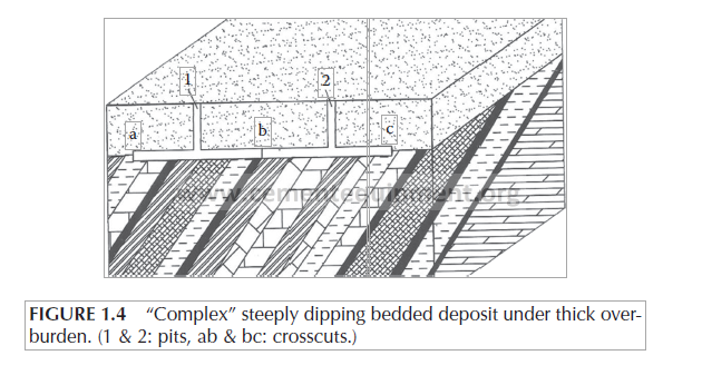
b. Complex deposits: medium to large consistent deposits, moder-ately to steeply dipping, gently folded (Figure 1.4).

c. Intricate deposits: highly complicated, highly folded and faulted,dislocated bodies, highly lenticular, often interbedded with clay or shale (Figure 1.5).
Resource, reserve, and exploitability
The intensity of prospecting and exploration is decided depending on the geological complexity of a deposit—a tentative idea of which can be obtained from Table 1.4. The ultimate objective of any such exploration program is to ascertain the quality and reserves of the deposits with some level of precision.
During the 1990s, the Economic Commission for Europe (ECE) took the initiative of developing a simple, user-friendly, and uniform system for classifying and reporting reserves and resources of solid fuels and min-eral commodities, primarily to harmonize the information and data origi-nating from different countries and multiple agencies. The result of these efforts was the creation of the United Nations Framework Classification of Reserves and Resources and Minerals and Commodities (UNFC 1997),

FIGURE 1.5 Geological disturbance in “intricate” deposits: (a) folding, (b) and (c) faulting of different types.

which was endorsed by the United Nations Economic and Social Council (ECOSOC) in the same year. In 2004, the classification was extended to oil, natural gas, uranium, etc. Later, for worldwide adoption, a simpler version was prepared in 2009, known as UNFC 2009 (9). It is a univer-sally acceptable and internationally applicable system and it is currently the only classification in the world to enjoy reasonable alignment with the templates and formats prevailing in a large number of international orga-nizations and committees engaged in the extraction of mineral wealth. It is a generic principle-based system in which quantities are classified on the basis of three fundamental criteria—e.g., economic and social viability (axis E), field project status and feasibility (axis F), and geological knowl-edge (axis G)—and it uses a numerical and language independent coding scheme. Combination of these criteria creates a three-dimensional system, as depicted in Figure 1.6. The E-axis designates the degree of favorability of social and economic conditions in establishing consumer viability of the project, including the coordination of market prices and relevant legal, regulatory, environmental, and contractual conditions. The F-axis desig-nates the maturity of studies and commitments necessary to implement mining plans or development projects. These considerations extend from the early exploration efforts to the stage of obtaining the project status, through all the intermediate phases. The third axis (G) designates the level of confidence in the geological knowledge and potential recoverability of the quantities. The categories and sub-categories are the building blocks of the system, as shown in Figure 1.7. Commercial projects in this context are the ones that are confirmed to be technically, economically, and socially feasible. The potentially commercial ones are the ones that can be devel-oped in the foreseeable future. The non-commercial projects include those that are at an early stage of evaluation and also those that are unlikely to be viable within a reasonable time, unless the restricting factors change.

FIGURE 1.6 Schematic diagram of the UNFC system of classifying mineral resources. (Reproduced from Economic Commission for Europe, United Nations Framework Classification for Fossil Energy and Mineral Reserves and Resources 2009, ECE Energy Series No. 39, United Nations, New York and Geneva, 2010. With permission from the United Nations.)

FIGURE 1.7 Classes and subclasses of UNFC system. (Reproduced from Economic Commission for Europe, United Nations Framework Classification for Fossil Energy and Mineral Reserves and Resources 2009, ECE Energy Series No. 39, United Nations, New York and Geneva, 2010. With per-mission from the United Nations.)
In UNFC 2009, terminologies such as “resource” or “reserve” have not been used, but in adopting the system in India the Indian Bureau of Mines, the apex organization engaged in discharging some of the important regulatory functions pertaining to the mineral and mining industry in the country, has merged the common terminologies with the numerical system (10). A “mineral resource” has been defined as a con-centration of naturally non-renewable material of the Earth, which is economically amenable to industrial utilization now or in the foresee-able future. Mineral resources have been further divided into “inferred,” “indicated,” and “measured” categories, in order of increasing geologi-cal confidence. On the other hand, mineral reserves, defined as eco-nomically mineable parts of measured or indicated resources, have been categorized into two main subdivisions, namely, “proved” and “proba-ble.” The IBM guidelines also include the broad directions of improving the levels of geological knowledge, the status of mining feasibility, and conformity with the economic viability requirements of the project. In line with international practice the highest category of mineral resource has the code (111) and the lowest category (334). A few illustrations of interpretation of the digital designations are given in Table 1.5.
The UNFC system-based categorization of mineral resources has been in practice in India for some time and the total limestone resources of all categories and grades as per the UNFC system were estimated in 2010 at 185 billion metric tons, as shown in Table 1.6 (7). Of the total quantity, about 69% is taken as cement-grade.


Reliability of different categories of reserves
According to the norms for proving limestone deposits (8), it has been specified that the cement-grade limestone reserves will be designated as possible, probable, and proved in the order of increasing reliability of estimates as indicated below:
• Possible reserve: Vg ≤ 4.0% and Vr ≤ 50%
• Probable: Vg ≤ 3.0% and Vr ≤ 30%
• Proved: Vg ≤ 1.0% and Vr ≤ 10%
where
Vg = anticipated deviation in CaO content from the actual value as mined, and
Vr = anticipated difference between the estimated and mined reserves.
Industrial implications of categorization of reserves
In addition to the above categories of reserves, which are estimated in the course of different phases of prospecting and exploration, another category of reserve, designated as “developed reserve,” is important for some complex and intricate deposits. This category of reserve is esti-mated after exploratory mining and should have Vg = 0.5% and Vr ≤ 5.0%. It is advisable to ensure developed reserves for about ten years for any modern large-capacity plant. In a working mine, the reserves should periodically be revised, audited, and reviewed based on the feedback data of mining and advance proving.
The basic information of limestone resources, which is based on regional geological studies or reconnaissance surveys, as they are often called, is generally used for the purposes of obtaining the prospecting license from the authorities empowered to give such permission in a country. The “proved” and “probable” categories of reserves obtained as a result of exploration are used for filing applications for mining leases from the concerned authorities. These categories of reserves are necessary for the preparation of project reports and for all financial decisions on project investments. The “possible” category of reserves is considered for future expansion purposes.
The requirement of the “proved” category of limestone reserves is arrived at after considering 15% mining losses, 30 years of plant life, 330 days of working of the kilns in a year, and specific consumption of 1.5 tons of limestone per ton of clinker. The “probable” reserve is expected to yield additional limestone of the “proved” category for an additional 15 years of plant life. This is computed by multiplying the estimated quantity of proven reserves for 15 years by a factor of 1.5 so that the required quantity is recovered from the probable reserves in the long run. No specific norms are as yet fixed for the “possible” category, but generally it is estimated at about 80% of the “proved” plus “prob-able” quantity. Following the above normative procedure, the required reserves for new large rotary kiln plants of various capacities are given in Table 1.7. In the case of small cement plants having capacities of up to 600 metric tons per day, mechanized mining is not a pre-requisite and the investment decisions may be taken on the basis of probable and possible reserves only. The tentative requirement of reserves for small plants is given in Table 1.8.
Sampling refers to the process of extracting small portions of limestone and associated rocks in the unprocessed state from a deposit such that the physical and chemical properties as determined for the small portion become representative of the whole. Depending on the phase of explora-tion, samples are drawn from outcrops of the rocks, natural sections of exposures, pits sunk, trenches excavated, boreholes drilled, and explor-atory mining work carried out.
In the reconnaissance of a deposit the rock samples are drawn by grab sampling at a particular place, which is unlikely to be representative, or by chip or point sampling, which is a collection along a line or a grid at regular intervals, or (even more representatively) by digging strips (1–2 m long × 10–30 cm wide × 5–10 cm deep) or grooves (2–5 m long × 10–30 cm wide × 15–30 cm deep). In the subsequent prospecting or exploration stages, recourse is taken to channel sampling and borehole sampling of different magnitudes. The channel samples are drawn by cutting channels normal to the planar structures of a deposit and aligned in the direction of maximum variation. The depth and width of the channel are kept uniform to the extent possible. The amount of cuttings to be collected per unit width of the bed depends on the nature of the rock and degree of variation. The borehole sampling is done in the form of cores drilled into the rock, along with the sludge that comes out. High core recovery of the order of about 90% is considered necessary for the proper assessment of a deposit. Cores are usually split longitudinally and one half is preserved for future refer-ence. The sludge sample is collected along with the cores in at least 10% of the boreholes drilled. The bulk samples are collected from pits or experi-mental excavations for pilot-scale technological testing. When the sectional


or individual samples drawn at close intervals are required to be combined into a composite sample, they are mixed in such a manner that the com-posite sample typically represents a bench height. There are other modes of sampling that exist essentially for operational or quality control purposes, such as from the blast holes of a quarry, which are not discussed here.
The length of the channel samples should have a relation with the borehole samples of the same deposit, as shown in Figure 1.8 and expressed by the following equation:

In the initial stage of exploration, when the effective thickness of the limestone bed is not known, sampling should be quite extensive. The thickness of beds, bands, and intercalations showing variation in their lithological composition and structural disposition should be sampled individually at intervals ranging from 0.5 to 1.0 m. Surface sampling at this stage should be done for every 10.0 m of length. In the subsequent phase of exploration, the sampling interval should be related to the thick-ness of a bed, its angle of dipping, and the bench height requirements in actual mining. For example, if it is assumed that a deposit would be

FIGURE 1.8 Relation between the sectional channel and borehole samples.
mined in benches of 10.0 m height, then field practice is to consider the sampling interval of 1.5 to 2.0 m for a bed dipping at 10 degrees or 2.0 to 3.5 m for beds dipping from 10 to 45 degrees.
Similarly, there are also norms for borehole samples. With large thicknesses of lithologically homogeneous beds, the borehole samples are drawn at intervals of not more than half the planned or customary bench height, which might mean a limit of 5.0 m. The topmost bench should have a greater number of samples as it generally contains more intercalations of clay and other rocks. The sampling pattern is modified when a deposit shows thick intercalations or bands of clay or shale or if there are irregular intrusions of other rocks.
The grab, chip, or channel samples primarily for chemical analysis may vary from 2 × 2 × 2 cm to 10 × 10 × 10 cm in size and 5–10 kg in sam-ple size. For mineralogical, physical, and mechanical tests the sample requirements are larger. The dimensions range from 20 × 20 × 20 cm to 30 × 30 × 30 cm or cores of 0.5–1.0 m length and correspondingly the sample size may vary in the range of 20–50 kg.
The bulk samples that are collected for technological tests should obviously be representative of the deposit, particularly when it is uni-form and homogeneous. For deposits showing considerable variation in quality, the bulk sample should represent the average material to be mined for feeding the plant. Hence, a bulk sample should be artificially prepared by mixing rocks from different parts of a deposit in such pro-portions that a sample would simulate the actual run of mine ore. The quantity of the bulk sample will depend on the type of test, the quality of the limestone, and the requirements of the testing organization. As a general guideline, an amount of 2.5 to 4.0 tons may be sufficient for run-ning pilot tests. One should also take note of the fact that the minimum quantity of bulk samples to be collected will depend on the diameter of the largest particle and the degree of heterogeneity, as given in Table 1.9.
Table 1.9 Relation between the sample quantity and particle characteristics


FIGURE 1.9 Reduction steps in sample preparation. (a) For homogeneous deposits. (b) For hetero-geneous deposits.
The reduction of all samples, other than the bulk sample, is carried out by sequential crushing, grinding, screening, and cone-quartering, as depicted in Figure 1.9. In such preparation of samples, proper care should be taken to retain one-half of the samples at each stage of pro-cessing for future reference and to pass the final portion of material at each stage through the screens of relevant dimensions.
Mineral composition and quality of limestone
The composition and quality parameters of limestone rocks have been considered in detail in (4) and the salient points are discussed here. Limestone is by definition a rock that contains at least 40% calcium car-bonate in the form of calcite mineral. All limestone occurrences contain small quantities of other minerals, such as quartz (SiO2), feldspar (alkali or lime silicate), clay minerals (hydrous aluminum silicates), pyrite (FeS2), siderite (FeCO3), etc., in the form of small dispersed particles. Some of the minerals, such as quartz or chert (an amorphous silica) and pyrite, may also occur as large nodules or veins in the deposits. Because of the carbonate content, however, limestone is easily detected in the field by its effervescence in contact with a cold solution of 5% hydro-chloric acid. The major calcium carbonate minerals and their important properties are furnished in Table 1.10.

Based on the mineral composition, limestone is classified as:
• Dolomitic limestone, when the percentage of calcium carbonate lies in the range of 40–80%, along with the presence of magne-sium carbonate.
• Siliceous, ferruginous, or magnesian limestone, when the percent-age of calcium carbonate lies in the range of 80–95% with associated minerals of siliceous, ferruginous, or magnesian types, respectively.
• Calcitic limestone, when the calcium carbonate percentage is greater than 95%.
There are various other ways in which limestone is named and classi-fied but for all practical purposes the above mineral-based classification is made use of in the field practices. In addition, on the basis of the mode of occurrence and texture, the limestone rocks are classified as follows (11):
• Chalk: a soft limestone with a very fine texture that is usually white or light-grey in color. It is formed mainly from the calcareous shell remains of microscopic marine organisms, such as foraminifera, or calcareous remains of numerous types of marine algae.
• Coquina: a poorly cemented limestone that is composed mainly of broken shell debris. It often forms on beaches where wave action segregates shell fragments of similar size.
• Fossiliferous limestone: a limestone that contains abundant fos-sils. These are normally shell and skeletal remains of organisms that produced the limestone.
• Oolitic limestone: a limestone composed mainly of calcium car-bonate “oolites,” small spheres formed by the concentric precipita-tion of calcium carbonate on a sand grain or shell fragment.
• Travertine: a limestone that forms by evaporative precipitation, often in a cave, to produce formations such as stalagtites, stalag-mites, and flowstone.
• Tufa: a limestone produced by precipitation of calcium-laden water at a hot spring, lake shore, or similar location.
Some typical microstructures of limestone are shown in Figures 1.10 through 1.14.
The National Council for Cement and Building Materials in India has drawn up the specification for limestone that is considered suitable for making Portland cement. The specification is given in Table 1.11 (8).
The reasons for specifying the limits of the constituents in Table 1.11 are as follows:
1. Sometimes there are opportunities of enriching the lime content in limestone by employing viable processes or to make available to a plant a sweetener-grade limestone at economic cost. Hence, the cut-off grade for the limestone is kept at 40%, although the desir-able range of lime content is defined as 44–52%. If a limestone is near-calcitic in composition, it can still be used as a raw material

FIGURE 1.10 Coarse-grained compact limestone.
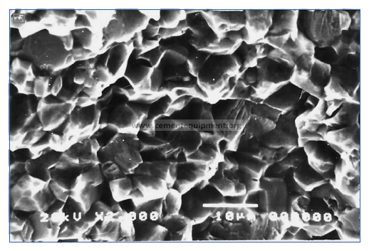
FIGURE 1.11 Fine-grained moderately compact limestone.

FIGURE 1.12 Limestone with inter-granular pores.

FIGURE 1.13 “Foraminifera” fossil in limestone.

FIGURE 1.14 Limestone with “oolitic” microstructure.

but the need for diluting the quality with corrective materials then increases substantially.
2. Since some of the standard global specifications for Portland cement permit composition of up to 6 per cent magnesia, the lim-iting value for this oxide in limestone is set at 3.5%. If, in some cases, it becomes unavoidable to admit higher contents of magne-sia, for example, up to 5%, this can only be done by lowering the proportion of magnesia to 3.5% by beneficiating the limestone or by blending it with a high-purity limestone.
3. The limiting values of R2O, SO3, and Cl¯ have been defined as they are volatile in nature and create “volatile cycles” in the kiln systems, leading to various operational and quality problems.
4. The limiting values of titanium dioxide, manganese oxide, and phosphorus pentoxide are dictated by the likely adverse impacts of these constituents on clinker quality.
5. The limit of free silica in the limestone is due to its adverse effects of abrasion on the crusher plates and in grinding mills, on one hand, and difficulties caused in the clinker burning process, on the other.
Typical physico-chemical properties of some limestone occurrences
It is important to note that a comprehensive characterization and evalu-ation of limestone includes the following:
• Hand specimen studies
• Chemical composition
• Mineral phase composition
• Microstructural characteristics
• Physical properties
• Thermal properties
• Mechanical characteristics
The overall assessment scheme for carbonate rocks is presented in Figure 1.15 and the scope of evaluation of the samples is given below:
• Chemical analysis for individual samples: CaO + MgO + CO2 or CaO + MgO + Insoluble residue.
• Chemical analysis for composite samples: SiO2 + Al2O3 + Fe2O3 + CaO + MgO + SO3 + Loss on ignition; if the sum total is 98.5% or less, P2O5 and R2O (alkali oxides) should be determined; if neces-sary, FeO, Mn2O3, Cl- may be determined.
• Petrographic analysis of parent rock and inseparable intercala-tions: quantification of MgO, R2O, SO3, and P2O5-bearing mineral phases, grain size, cementing material, and special textural fea-tures, if any.
• Granulometric fractions obtained by mechanical analysis: com-plete characterization and estimation of free silica in all fractions and also details of mineral contents of inclusions, particularly with sizes greater than 0.09 mm.
• Physical properties: specific gravity, bulk weight, porosity, natural moisture content, and water absorption.
• Mechanical properties: hardness, compressive strength, crushing index, grinding index, and abrasion index.
In order to help understand the pattern of physical and chemical properties of limestone rocks belonging to geological basins of different ages, some relevant Indian data are furnished in Table 1.12.
From Table 1.12 it is quite apparent that the physical properties of limestone rocks cannot be easily correlated with their chemical com-position. Hence, in most of the situations, limestone samples need to be characterized as comprehensively as possible. By and large, it is observed that the Mohs hardness of sedimentary limestone rocks falls in the range of 3–4, and the density in the range of 2.5–2.7 g/cm3. The porosity of compact limestone rocks may range from 1–20% and it may go up to 30% in porous limestone. Water absorption depends on the pattern and level of porosity. While it is generally negligible for com-pact limestone, water absorption may go up to 20% in porous limestone.

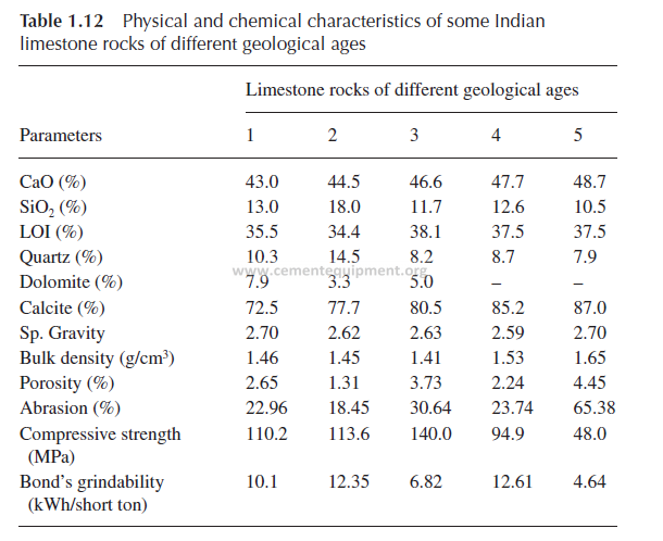
The compressive strength of cylindrical specimens prepared from the lumps of limestone samples vary from 10 to 200 MPa, and the Bond’s grindability index from 4 to 14 units.
In general, the desirable characteristics of limestone from a cement manufacturing point of view can be summarized as follows:
a. Average calcite crystal size: less than 0.25 mm, which is consid-ered characteristic of fine-grained rocks
b. Absence of coarse quartz and silica veins
c. Low moisture content: less than 5%
d. Low compressive strength: less than 100 MPa
Limestone mining
Limestone is predominantly mined from a quarry that is an open pit exposed to the surface. However, underground limestone mines can be found in the central and eastern USA, Brazil, and some other coun-tries, especially in and near cities. Underground mining obviously has some advantages over surface quarrying but, since it is more expensive and capital-intensive, the cement industry depends mostly on opencast mining. The suitability of opencast mining is also due to the fact that the sedimentary limestone deposits are quite extensive, covering hun-dreds of square kilometers, and are reasonably uniform in thickness and quality.
The selection of mining method is dependent on several factors. The more important criteria are:
• Shape and configuration of the deposit
• Aerial extent and dimension
• Dip (inclination) and thickness of the bed
• Thickness of the overburden
• Physiographic and topographic conditions
• Climatic conditions including rainfall, snowing, wind pattern, etc.
• Daily and yearly raisings required for feeding the plant
Variations in open-cast mining
Some variations in the opencast mining methods under different con-ditions are briefly described below.
For deposits in plain land the mine is opened at a point where the thick-ness of overburden is minimal. Inclined trenches and ramps are driven from one bench level to another in order to create and develop each bench. In hilly deposits, mining has to start from the top downwards, by slicing or decapping. The benches are developed at pre-determined locations. For thick limestone deposits that are horizontally bedded with a thick layer of overburden, the mining operation is mostly mechanized with large-capacity mining equipment, while for deposits with thin mineral-ization and thick overburden, or vice-versa, the operation is mechanized but with medium-capacity equipment. For deposits with a thin bed of mineralization and a thin layer of overburden, only a semi-mechanized scheme is adopted. The same principles hold good for deposits with dip-ping beds but a major consideration in this case is the economic depth of mining. The “stripping ratio,” signifying the ratio of limestone to over-burden or waste rock, is normally very important in mining but turns out to be critical in steeply dipping deposits. The economic or cut-off stripping ratio (COSR) is defined by:
COSR valueofa unit quantity of limest=−one averagecosttofproduction/
averagecostof overburdenremoval
and the formula brings out the break-even point at which the mining operation is no longer profitable. An important alternative method of working for dipping deposits is to mine along the strike direction or per-pendicular to the dip direction of the bed, instead of advancing along the dip. This method of mining is known as “terrace mining” and is often preferred for both economic and environmental reasons.
Most opencast mining operations are discontinuous. Nowadays, a continuous system is preferred in appropriate situations by using a spe-cial piece of mining equipment called a “surface miner.” This equipment cuts the rock continuously and feeds the conveying system. One great advantage over conventional systems is that it does not require drilling
and blasting as well as primary crushing of rock. At the same time, one must take into consideration its limitations. It can cut freely only softer limestone rocks with compressive strength of up to 50 MPa, or up to 80 MPa if the rock has cracks, crevices, and fissures, or if the seismic velocity of the rock is low.
Normally, cement plants are located near the limestone deposits, while shale or clay is either substituted by the overburden, if it is chemically suitable and economical to use, or mined locally elsewhere and trans-ported to the plant. Other corrective materials are usually brought from outside.
Mining plans of the limestone quarry are developed according to the nature of the deposit. If the limestone is not homogeneous, it may be necessary to blend rock from different benches and faces of the mine in order to maximize the recovery from the mine. In some mines, it may be necessary to undertake selective mining in order to avoid low-grade material or problems of associated harmful constituents like sulfates and alkalis.
The mining operation proceeds with initial close-spaced advance drilling and analysis of drill hole samples in order to ascertain the spa-tial distribution of quality. The areas to be blasted are decided based on such advance drilling. The conventional explosive used for limestone quarrying is ANFO (ammonium nitrate with 5% fuel oil). The specific consumption of explosives varies depending on the blasting behavior of limestone, but tentatively it is in the range of 200 g/t.
If, after primary blasting, the limestone boulder size is larger than the crusher feed size, there could be a need for secondary blasting or mechanical size reduction of the biggest boulders. The run-of-mine material, after blasting, is transported to the crusher. Mining and haul-age operations are generally monitored by
a. Blasting factor: grams of explosive per metric ton of rock.
b. Overburden ratio: tons of waste rock removed per ton of useful rock.
c. Loading rate: tons of rock per hour of loading equipment availability.
d. Hauling factor: tons of rock transported per truck and truck availability.
It should also be borne in mind that all mine output and inventory records are kept on the basis of dry rock data but the moisture levels of mined, hauled, and crushed rocks are used for assessing the equipment efficiency.
Typical public concerns about limestone mining include dust, noise, blasting vibration, and vehicular traffic. Some limestone rocks are aqui-fers and there can be concerns about the contaminants from quarry oper-ations escaping into the groundwater. In humid climates, large amounts of limestone dissolve and are carried away in the flowing water, creating sinkholes.
Quarry design and operational optimization
The design of a pit for opencast operation may look simple but it involves not only proper utilization of exploration data through build-up of a 3D model of the deposit, but also reasonable integration of various other factors such as geotechnical, economic, operational, and environmental considerations. The configuration of the quarry, along with its bound-ary limits, has to be defined through the development of a 3D model from the exploration data. Parameters like slope stability, the dimen-sions of the working benches and their compliance with the prevail-ing mining regulations, water seepage and drainage, layout of the road network, determination of blasting behavior of rocks, etc. fall primarily under the purview of geotechnical modeling. Environmental planning includes, apart from the minimization of dust and noise pollution at the operational stage, the design of a waste rock dump, the systematic clo-sure of mines, and the rehabilitation of the quarry after closure. The economic model involves assessment of the economic stripping ratio, determination of the net present value of future mining operations, and the overall viability of the project. Thereafter, operational issues such as grade control, scheduling of mining sequence, opening-up of mine faces, planning of blasting pattern, advance drilling program, etc. are decided. Long-term integrated mine planning is, therefore, complex and has many components, as shown in Figure 1.16.
Regarding actual operations, in a quarry the planning system must pass information to drill operators. Drilling operations need to send samples from advance drilling operations to the laboratory, and the

FIGURE 1.16 Components of integrated long-term mine planning.
grade control geologist needs to match up the quality of blast holes with their actual positions and depths. The blasting engineer needs to know which drill holes are in limestone and which are in waste rocks. The dispatch system needs to know which faces are to be mined, what the tonnages are, and where the crusher is. It is obvious, therefore, that the quality control of run-of-mine limestone and the optimiza-tion of quarry operation are quite involved and complex. Present-day mining software packages allow rapid and accurate iterative investiga-tions of mining scenarios to determine the most appropriate course of action. Among the numerous software packages, those commonly used include GEOVIASurpac, Maptek Vulcan, Datamine, XPAC, iGantt, Micromine, and Promine.
The basic feature of these software packages includes a relational geo-logical database that allows storage and query of all geochemical quality parameters, in addition to physical attributes such as minimum mining thickness. Complex 3D geological and quality models are developed to assist in deposit visualization and estimation of fairly accurate volumes. Statistical and multiple-element compositing tools can be used to inves-tigate the quality distribution and undertake element combinations using established algorithms. Estimation using a polygonal, grid, or block model approach is available in such software. The effect of lateral quality varia-tion can be minimized using the proper scheduling approach. A sched-uler allows an engineer to examine multiple mining scenarios graphically and with ease. Such software can assist the plant manager in optimiz-ing a blend of raw material from available quarry faces. These solutions use linear programming to achieve the required blend and are useful in ensuring that short-term goals are met. The long-range quarry schedul-ing problems require a rigorous solution and make use of dynamic pro-gramming methods. The plant quality targets for cement making can include several parameters such as directly measured minor constituents like MgO, SO3, R2O, etc. and other critical modulus values. While the 3D geological model is built to contain quality values, interpolated from drill cuttings and face samples, the schedule optimizer is able to utilize these basic quality attributes in constructing the target ratio of blending lime-stone mined from different blocks and faces. On the whole, therefore, the quarry production plan is essentially based on geological exploration data, 3D deposit modeling, grade control, scheduling of mining sequence, and ore blending (Figure 1.17), and planning functions include blast design and layout. Also included is the evaluation of blast operations and schedules are developed to plan production from the working benches. It should also be borne in mind that conventional economic analysis tells us that the value of an ore block mined today is worth more than an ore block mined one year from now. Hence, certain software packages have developed pro-grams to solve the problems of how to discount the value of mining blocks and consequently locate the optimal limit of mining.

FIGURE 1.17 Sequential steps in quarry planning.
Argillaceous materials
The expression “argillaceous materials” refers to all fine-grained natural earthy substances that are alternatively known as “clay,” including shale and argillite. It is well known that the clay minerals are part of a larger family of phyllosilicates and are characterized by interlinked tetrahedral and octahedral sheets. The chemical composition and structural con-figuration of clay minerals have been discussed in detail in (4,12). The structure and properties of the major clay mineral groups are presented in Table 1.13.
From the table it is evident that, chemically, these materials are hydrous aluminum silicates, with magnesium or iron substituting alumi-num wholly or in part in certain minerals, and with alkalis or alkaline earth also present as essential constituents in a few others.
Some argillaceous materials are composed of a single clay mineral but in many there is a mixture; in addition to the clay minerals, many argil-laceous materials contain non-clay minerals like quartz, calcite, feld-spar, sulfides, and so on. Many others may contain organic substances as well as water-soluble salts, and some clay materials may contain phases that are x-ray amorphous. The multitude of variation in clay minerals is caused by substitution in the octahedral and tetrahedral layers, resulting in charge deficits. The manner in which the charge deficit is balanced leads to many of the useful and unique properties of clay minerals. As a result of such diversity of constitution of argillaceous materials, their technical assessment for specific applications is rather complex. Broadly

speaking, the property-controlling factors in argillaceous materials are the following:
i. Clay minerals
ii. Non-clay minerals
iii. Organic substances
iv. Exchangeable ions and soluble salts
v. Particle characteristics including shape, size, and orientation
vi. Structural assembly formed by 1:1 or 2:1 linkage of tetrahedral and octahedral sheets as well as neutralization of excess layer charge by various interlayer materials
Thermo-chemical reactivity of clay minerals
Argillaceous rocks generally show the presence of multiple clay miner-als. Shale generally contains illite and chlorite. Montmorillonite is also a common constituent of many shale occurrences of Mesozoic age and younger. Kaolinite is a common mineral of certain types of shale but usually in minor proportions. Slates are also composed of illite and chlo-rites but with a higher degree of crystalline structure. The carbonate rocks show the association of a wide range of clay minerals, illite and chlorite being more predominant than kaolinite and montmorillorite.
Experience has shown that an aluminum silicate phase, when pres-ent in raw mixes from the argillaceous component, turns out to be sig-nificantly more reactive than fine-ground silica. It has been generally observed that the water vapor and hydroxyl ions released from the argil-laceous materials show some catalytic effect on the dissociation of cal-cium carbonate and the subsequent solid-state oxidation reactions. The trend of decomposition of a few clay minerals is shown in Table 1.14. It is
Table 1.14 Decomposition behavior of some clays of varying mineral composition based on thermogravimetric analyses

evident that the temperature ranges over which different clay minerals release water and hydroxyl ions to become amorphous and reactive are not the same. It is obvious, therefore, that their reactivity with lime and other oxides would not be identical in different situations. However, there is still no unanimity in the views of different investigators regarding the order of reactivity of different clay minerals. According to certain inves-tigations (13), montmorillonite as a clay mineral is more reactive than kaolinite, which in turn shows higher reactivity than chlorite. Minerals like muscovite, biotite, vermiculite, pyrophyllite, etc. in general have low reactivity.
It may also be borne in mind that the argillaceous materials have high probability of containing titania, alkalies, sulfides, sulfates, and phos-phates. The reactivity may get strongly influenced by the presence of the above constituents.
Corrective materials
When the primary components of a raw mix do not jointly permit the desired range of modulus values to be achieved, a third or even a fourth component is added, known as corrective materials. It has been a prac-tice to recognize that a material with more than 70% silica, 40% iron oxide, or 30% alumina can be termed as siliceous, ferruginous, or alu-minous corrective material (14).
Sand, sandstone, or quartzite acts as the source of siliceous correc-tive material. Other conditions being equal, the grain size and specific surface of silica in free form, and particularly of the least reactive forms like quartz and chalcedony, determine the rate of reaction in a kiln feed. The reactivity of different types of silica, free or combined, increases in the following order:
quartzchalcedony<<opa <−lcristobalite anααd-tridymmite
< silica fromfeldspars silica fro<m micaand amphiibole
< silica fromclay mineralssilica fromg<lassy sllags
On the whole, silica in amorphous state or derived from silicates or hydrosilicates is preferable to silica in other forms.
The correction of iron oxide in a raw mix is generally done with iron ore, which may either be magnetite or hematite. A hematite with colloidal texture or martitized magnetite is quite reactive with lime and alumina. Limonite (FeO.OH.H2O) often associated with laterite is more reactive than the ferric oxide hydrate phases like goethite and lepidocrocite. It has been observed that the reactivity of raw material is often favorably influenced by the presence of iron oxide in the ferrous state, the appear-ance of which is obviously dependent on the parent mineral. For example, chlorite and glauconite may release FeO below 500°C, while goethite and lepidocrocite yields Fe2O3 at about 300°C. The iron-bearing miner-als, thus, play some important role in shaping the reactivity of kiln feed.
The correction of alumina is done with the help of bauxite or alumi-nous laterite. These rocks contain such aluminous minerals as gibbsite
(Al2O3.3H2O), bohemite (α Al2O3.H2O), and diaspore (βAl2O3.H2O). Generally, these phases show low crystallinity and high energy in the green state, dehydrate at 300–500°C, and give rise to different forms of alumina that ultimately define their reactivity at higher temperatures.
Natural gypsum
Gypsum (CaSO4.2H2O) is a common rock-forming mineral with thick extensive beds formed by the evaporation of extremely saline water. It is often associated with other minerals like halite or sulfur. It is depos-ited from lakes, seawater, hot springs, volcanic vapors, etc. and usually forms a solid nonporous rock near the Earth’s surface, and consequently the mining of gypsum ore is generally carried out in quarries or shallow underground mines. It is a mineral belonging to the monoclinic system and mostly occurs as flattened crystals that are often twinned. It is a very soft mineral, having a Mohs hardness of 1.5–2.0 and density in the range of 2.31–2.33 g/cm3. Gypsum is white, grey, or reddish in color, depending on the presence of clay or iron oxide; the color may be black or nearly black if bitumen is present. Depending on the appearance and crystalline characteristics, gypsum is known by certain other names. A fine-grained white or slightly tinted variety is known as “alabaster”; a transparent colorless variety with pearly luster is called “selenite”; and a silky fibrous variety is named “satin spar.” When the white variety is used for agricultural purposes, it is known as “terra alba” or “land plaster.” An unusual and interesting occurrence of white gypsum is in New Mexico in the USA, where it covers an expanse of 710 km2 with a dune-like structure. This deposit is not being exploited and is preserved as an uncommon occurrence (15).
World production of gypsum in 2012 was 150 million metric tons, with China being the largest producer, followed by Iran, Spain, Thailand, and the USA. The production statistics of the first ten countries of the world in the same year are given in Table 1.15 (16).
According to IBM statistics, in 2010 gypsum production in India totaled only 2.5 million metric tons. Over the years, the resource position of the mineral gypsum has declined and the emphasis has been shifting towards the use of chemical gypsum primarily from the fertilizer indus-try. The state of Rajasthan alone accounts for over 81% of resources, and Jammu and Kashmir 14%. The remaining 5% of resources are distrib-uted in Tamil Nadu and other states.
Gypsum is worked by opencast manual mining, except in a few semi-mechanized mines in Rajasthan. The deposits are found at shallow depths and scattered over large areas. Production is classified into four grades based on the calcium sulfate (CaSO4.2H2O) content: (i) above 90%; (ii) 85–90%; (iii) 80–85%; and (iv) less than 80%. High-grade gypsum is mined in the Bikaner and Jaisalmer districts of Rajasthan.

Some gypsum mines in the Bikaner district also produce the selenite variety. Rajasthan gypsum is used in cement plants in northern and eastern states in India, while gypsum produced in Tamil Nadu is mainly of cement grade and is consumed in plants located in the southern parts of the country.
The CaSO4 – H2O system is represented by three solid phases that co-exist at room temperature in air containing water vapor, namely cal-cium sulfate dihydrate (CaSO4.2H2O), calcium sulfate hemihydrate (CaSO4.1/2H2O), and insoluble anhydrite (CaSO4 – insol.). In addi-tion to these phases, another phase is identified as soluble anhydrite (CaSO4 – sol.), which has the same crystal structure as hemihydrate. Two transformations are very important for these substances. They are (1) dehydration from the dehydrated state and (2) rehydration to the dehydrated state. Dehydration refers to the stepwise loss of water of hydration that is accomplished by increasing the temperature of dehy-dration for the purpose of obtaining one of its dehydration products, i.e., hemihydrate, soluble anhydrite, and insoluble anhydrite. The tempera-ture ranges applicable for the individual dehydration steps depend on whether the process is static or kinetic. In general, the static conditions appear to proceed at a lower temperature but they require more time. For example, the dihydrate phase begins to dehydrate at about 46°C but conversion takes months or even years to complete. Rehydration is the exposure of these dehydrated materials (hemihydrate, soluble anhydrite, and insoluble anhydrite) to liquid water for the purpose of obtaining the dihydrate state again at standard conditions. This process proceeds by the crystallization of the dihydrate phase in water. If the starting mate-rial is a hemihydrate, a supersaturated solution is formed prior to crystal-lization. In the case of an insoluble anhydrite as the starting material, the rate of conversion to gypsum is affected by the degree of its solubility and the temperature. The solubility of the dihydrate, hemihydrate, and insoluble anhydrite phases are an important consideration for a vari-ety of reasons but primarily because they allow a distinct separation between the three phases on a theoretical basis. Their approximate solu-bility curves are shown in Figure 1.18 (17).
The intersection between two curves gives the equilibrium tempera-ture, below which the less-soluble phase is stable. For example, the curves show that above 40°C (point A) insoluble anhydrite is the most stable phase. However, above this point, the dihydrate phase, if in contact with water, should not convert to insoluble anhydrite, but in practice It may do so but at a very slow rate. Below 100°C (point B) the dihydrate phase is more stable than the hemihydrate. When the saturated solutions of hemi-hydrate are supersaturated with respect to dihydrate, the dihydrate phase precipitates from the solution. This dehydration-rehydration process appears to be relatively simple but a number of critical conditions are to be met that finally ensure the transformation process. For example, water vapor plays a significant role in the dehydration and rehydration of
soluble anhydrite. Also, the hemihydrate phase occurs in the α-form and ß-form depending on the method of dehydration. When the hemihydrate
phase is formed under normal atmospheric conditions it is referred to as
β-hemihydrate, while the α-form is obtained from the dihydrate phase by autoclaving. Although the normal solubility of the dihydrate phase is
reckoned as 2.1 g/L at 20°C, the solubility of the β-hemihydrate is much higher at about 8.8 g/L at 20°C but it reduces to 6.5 g/L for the α-phase. For all practical purposes, the conversion temperature of dihydrate to hemihydrate lies in the range of 100–180°C, hemihydrate to soluble anhydrite in the range of 180–350°C under favorable water vapor pressure conditions and to insoluble anhydrite above 1180°C. Insoluble anhydrite also occurs in natural deposits.

Influence of raw materials on unit operations
In the cement production process, since there are quite a few unit opera-tions employing different equipment and machinery, it is important to examine the influence that the raw materials yield in this perspective. For example, all three principle unit operations such as crushing, grind-ing, and burning are strongly influenced by the characteristics of lime-stone and other raw materials. Some key requirements include:
• Crushing strength (kg/cm2) or crushability index
• Grinding index
• Hardness
• Abrasion index
• Impurities present such as clay, quartz, etc.
• Degree of coarseness in terms of crystal size of the constituent minerals
• Particle size distribution of the crushed and ground materials
• Moisture content (minimum and maximum)
While the first three parameters are important for selection of the type and materials of construction of the crushing and grinding installa-tions, the other parameters may have a strong influence on the process. It is observed that the handling of wet sticky materials may affect the throughput and increase the maintenance cost of the crusher. Similarly, most materials to be crushed contain inclusions or impurities, which behave quite differently from one another when introduced into a crusher or a screening system. The characteristics of these inclusions play an important part in the selection of the right equipment.
Coming to the grinding process, the objective is to achieve the tar-geted particle size distribution, average particle size, and specific surface with least consumption of energy and other operating costs. Ball mills are cost-effective only when a high degree of wear is expected due to, say, high quartz content. High pressure grinding rolls can profitably be used for relatively dry raw materials. Roller mills are generally preferred for raw grinding due to their low energy consumption and the option of simultaneous drying. So far as burning is concerned, it is important to note that different raw mixes with more or less the same chemical composition and similar fineness may have greatly differing burning behavior. The reason for the difference lies in the variation of the min-eral composition of the raw mix constituents, their crystal size, and their particle size. Worldwide experience has shown that the poor burning is
primarily caused by the presence of coarse grains of quartz (+ 44 μm), calcite (+ 125 μm), feldspar (+ 63 μm), and shale (+ 50 μm).
The volatile matters and, more particularly, alkalis and chlorides present in the raw materials have a very strong bearing on the process of clinker formation in the present-day preheater-precalciner rotary kilns. The circulation of these volatiles in the system without any bypass imposes certain upper input limits for these constituents in raw mixes.
The determination of alkali-, sulfur-, and chloride-bearing minerals in the raw materials becomes essential in this context. Some of these aspects will be discussed in more details in chapters dealing with size reduction and burning operations.
Summary
Cement production is dependent on a wide range of sedimentary and metamorphic rocks, limestone being the essential one. A limestone resource required for setting up a cement plant needs to be first exam-ined from the point of view of its quality and quantity. The geologi-cal disposition defines the complexity of a deposit and an appropriate exploration program is necessary for proving the deposit and arriving at a reliable estimate of reserves. A general approach is to classify the deposits in terms of their geological complexity so that the quantum of exploration could be decided for a given deposit, which in turn will ensure that proper reserve estimates are made in “proved,” “probable,” and “possible” categories of reserves. The limestone reserves can be more rationally categorized by applying the United Nations Framework Classification system, using three parameters, viz., status of geological proving, extent of mining feasibility established, and compliance of eco-nomic and social viability of the project studied. This system provides a more dependable approach to transform a resource into a viable mine through various intermediate stages of investigation.
The assessment of limestone deposits involves sampling of different types at different stages of investigation. Standard operational proce-dures have been evolved in practice for such sampling exercises, which need to be observed in the studies. The dependability of technological assessment of limestone deposits is related to the representativeness of the samples drawn and evaluated.
Limestone mining is done mostly by the opencast method. The details of the mining method depend on the shape, size, and configuration of the deposit, terrain of its occurrence, disposition and thickness of the bed, overburden or waste rock to be removed and dumped, and several other factors. Parameters like the blasting factor, overburden ratio, loading rate, and so on are required to be monitored in the mining operation. Quarry design and operational optimization are essential steps in min-ing and several software packages are available to undertake these steps.
After proving a limestone resource, it is essential to undertake its thorough technological assessment. Limestone with a minimum of 44–45% CaO and maximum 3.0–3.5% MgO, 0.6% R2O, 0.6–0.8% SO3, and 0.015–0.05% Cl is regarded as a cement-grade limestone, provided its SiO2, Al2O3, and Fe2O3 contents satisfy the desired modulus values of raw mixes. The specification of clay and other corrective materials can-not be very precisely defined as they have to have compatibility with the principle carbonate component. In general, an argillaceous component with more than 3% R2O and 1% SO3 may be considered, prima facie, unsuitable. For most of the minor constituents, 0.5% is regarded to be a
safe limit. If some of the constituents exceed this limit, a special exami-nation is called for.
The size reduction and thermal behavior of raw materials primarily depend on their mineral phases and microstructural features. The crystal size of calcite and the associated mineral assemblage define the dissocia-tion characteristics of limestone in a very effective manner.
The mineralogy of argillaceous materials is quite complex due to their layered structure, frequent ionic substitutions in the layers, unbal-anced charges, and the inclusion of interlayer materials. Because of these complications the choice of clay can be guided more by Si/(A,F) ratio, volatile contents, fusibility, particle size distribution, cation exchange capacity, etc. In the ultimate evaluation, it is important to note that the concurrence of carbonate dissociation and thermal decomposition of clay and other corrective materials is considered a basic necessity for high reactivity and proper burning.
The above concepts are equally applicable for all other siliceous, fer-ruginous, or aluminous corrective materials, when their use becomes unavoidable due to stoichiometric needs. Different forms of silica, alu-minum hydrates, ferriferous minerals, etc. present in the above cor-rective materials influence the burning process quite significantly and hence demand careful evaluation in terms of overall impact on the burn-ing behavior of the raw mix.
Mineral phases carrying volatile oxides like alkalis, sulfates, chlo-rides, etc. assume criticality in determining the likely nature of the vola-tility cycle in a rotary kiln system. Hence, the selection of raw materials depends on the quantitative contribution of such volatile components from the raw materials under consideration.
In cement production, size reduction is an important material prepa-ration step. The amenability of limestone to size reduction processes is apparently controlled, inter alia, by the free and fixed silica content and the crystal size variations of calcite and quartz phases. The selection of hardware for grinding is also dependent on the above mineralogical and microstructural features.
Since the ultimate burning process is dependent on the prior size reduction steps, there has been a progressive evolution of the concept of limiting particle size for different mineral forms, supported by experi-mental findings. In the selection of raw materials, the feasibility of attain-ing such particle size distribution patterns requires specific attention.
All in all, it should be realized that the production of cement is solely dependent on natural raw materials and, more specifically, on the qual-ity and quantity of limestone. The scale of operation is large and the location of a plant for its life is decided by the occurrence of a limestone deposit. The technological suitability and consistent supply of raw mate-rials are, therefore, of paramount significance. Proper selection of raw materials is the first step towards setting up a cement plant.
References
1. http://en.wikipedia.org/wiki/limestone, retrieved on June 21, 2017.
2. E . S. Dana and W. E . For d, A Textbook of Mineralogy, John Wiley & Sons. Inc., New York (1955).
3. V. R zh evsk y and G. Nov i k, The Physics of Rocks (Translated from Russian by A. K. Chatterjee), Mir Publishers, Moscow (1971).
4. A. K. Chatter j ee, Raw materials selection, in Innovations in Portland Cement Manufacturing (Eds J. I. Bhatty, E. M. Miller and
S. Kosmatka). Portland Cement Association, USA (2004).
5. J. A. H. Oate s, Lime and Limestone, John-Wiley-VCH Verlag GmbH, Weinheim (1998).
6. http://geology.com/usgs/limestone, retrieved on June 21, 2017.
7. Indian Bureau of Mines, Indian Mineral Year Book 2013, IBM, Nagpur, India (2015).
8. National Council of Cement & Building Materials, Norms for Proving Limestone Deposits for Cement Manufacture, NCB, New Delhi (2003).
9. Economic Commission for Europe, United Nations Framework Classification for Fossil Energy and Mineral Reserves and Resources 2009, ECE Energy Series No. 39, United Nations, New York & Geneva (2010).
10. Indian Bureau of Mines, Guidelines under MCDR for United Nations FRAMEWORK Classification of Mineral Reserves/Resources, Nagpur, India (2003).
11. http://geology.com/rocks/limestone.shtml, retrieved on June 21, 2017.
12. A. K. Chatter j ee, Pozzolanicity of Calcined Clay, in Calcined Clay for Sustainable Concrete, Proceedings of the International Conference on Calcined Clay for Sustainable Concrete (Eds K. Scrivener and A. Favier), Springer (2015).
13. V. V. Volkonsk i i, S. D. Makashev, and N. P. Shtei rt, Technological, Physico-Mechanical and Physico-Chemical Studies of Cement Raw Materials (in Russian), Izd-vo Literatury Po Stoitel’stvu, Leningrad (1972).
14. A. K. Chatter j ee, Chemico-Mineralogical Characteristics of Raw Materials, in Advances in Cement Technology (Ed. S. N. Ghosh), Pergamon Press, Oxford (1984).
15. http://www.newworldencyclopedia.org/gypsum, retrieved January 24, 2014.
16. USGS Mineral Commodities Summary – Gypsum (2016).
17. H. F. W. Taylor, Cement Chemistry, Academic Press, London (1990).
To Download Everything About Cement crushers , Kilns , Vertical mill , Cement mill , … ETC kindly click here now
To Download Everything About Cement crushers , Kilns , Vertical mill , Cement mill , … ETC kindly click here now
I have liked your document for good and helpful materials contained within it.
Thank you for your help.