Alternative fuels and raw materials
Attention : click here to Download Most Important books + manuals + excel sheets + formulas + everything you should know in Cement industry , CLICKHERE NOW
Preamble
In cement plants, the use of agricultural and industrial wastes is becom-ing increasingly important, on account of both economic considerations and environmental compulsions. The economic considerations arise from the fact that the costs of raw materials and fuels comprise as much as 50% of the total operating costs in most of the plants and, therefore, alternative fuels and raw materials with cheaper cost implications find an important role to play. The environmental compulsions occur due to enormous increases in the generation of wastes that require safe and gainful modes of recycling.
Wastes are generated from diverse sources, which include our mode of living, agricultural practices, and industrial operations encompassing mining, processing, and manufacture. Plastic wastes, municipal solid wastes, organic solvents, scrap motor tires, electronic garbage, and ani-mal carcass wastes are just a few examples. The cement industry has a proven track record of being well adapted to absorbing and utilizing these waste products in the production of cement. The problems of recy-cling the waste have essentially been threefold: environmental concerns associated with the transport of such materials to the facilities, conse-quences of their use in the cement process, and contending with various operational and quality issues online.
Looking at the abundance and variety of wastes around us, one must accept that alternative fuels and raw materials are changing both quanti-tatively and qualitatively. In such a dynamic situation of waste manage-ment, the legislation and technologies for processing and treatment are undergoing rapid development, which is clearly influencing the material flows. Therefore, the material data presented in this chapter cannot be considered universal and have to be verified for each situation. Further, it is important to mention that the availability of wastes depends on the cultural, social, and economic activities of a country or a region. The net effect of all these factors is the emergence of a new operational strategy in the cement industry, designated as “AFR” or “Alternative Fuels and Raw Materials.”
Broad classification
The agricultural and industrial wastes may either be incombustible or combustible. The incombustible wastes include coal ash—more com-monly identified as fly ash, bottom ash, and mixed pond ash—from the thermal power generating plants; slags from the metallurgical industry, of which granulated blast furnace slag is more widely used, and steel slag from the iron and steel industry and copper slag and lead-zinc slag from the nonferrous industry is less widely used; lime-containing sludge from paper and chemical production; used pots from the aluminum industry, etc. This chapter focuses on combustible waste and does not deal with the above material in detail.
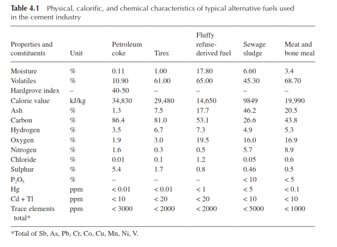
Combustible wastes may come from both the agricultural and indus-trial sectors. Agricultural waste, often called biomass residues, mainly consists of rice husk, bamboo dust, bagasse, straw, coconut husk, pea-nut husk, wood waste, etc. Industrial wastes cover both non-hazardous and hazardous varieties and include carbon slurry from fertilizer plants (that use coal for the production of CO2), petrochemical waste, spent pot-liners from the aluminum industry, waste oils from gearboxes and machines, hazardous wastes from pesticides and pharmaceutical indus-tries, scrap motor tires, rubber wastes, plastic waste, cardboard, graph-ite dust, old battery boxes, etc. A third variety of combustible waste is broadly identified as household waste, animal waste, municipal refuse, sewage sludge, landfill gas, etc. The composition and properties of a few of these alternative fuels are given in Table 4.1 (1).
In terms of the physical state in which the combustible wastes are generated, they are classified as follows:
- Gaseous: coke oven gas, refinery waste gas, pyrolysis gas, landfill gas, etc.
- Liquid: low-chlorine spent solvents, lubricating oils, vegetable oils, fats, distillation residues, hydraulic oils, insulating oils, etc.
- Pulverized, granulated, or fine-crushed solids: waste wood, saw-dust, wood shavings, dried sewage sludge, finely shredded used tires, residues from food production, etc.
- Coarse crushed solids: plastic waste, discarded wood strips, re-agglomerated organic matter, etc.
- Lumpy solids: whole scrap tires, plastic bales, plastic bags, and plastic drums, etc.
- Refuse-derived fuel of specified dimensions.
Definition of hazardous wastes
- A hazardous waste is defined as any waste that by virtue of its physical and chemical properties causes danger or is likely to cause danger to health and environment, alone or in contact with any other waste mate-rial or substance. The basic characteristics of hazardous waste are:
- Corrosivity: the ability to destroy tissue by chemical reaction. Known examples are rust removers, waste acid, alkaline clean-ing fluids, and waste battery fluids. Corrosive substances have pH value either below 2.0 or more than 12.5.
- Ignitability: ready oxidization by burning; spontaneously com-busting at 54.3°C in air or at any temperature in water; strong oxidization leading to combustion; any non-liquid material capa-ble of causing fire under standard temperature and pressure due to friction, moisture absorption, or spontaneous chemical change. Common examples are coating wastes, paint, certain degreasers and solvents.
- Reactivity: the ability to react, detonate, or decompose explosively at environmental temperature and pressure. This property can often be found in wastes from cyanide-based plating operations, bleaches, waste oxidizers, and waste explosives.
- Toxicity: the capability of causing harm to organisms. This is char-acterized by the toxicity characteristics of 37 elements (such as arsenic, cadmium, chromium, mercury, lead, etc.) and organic com-pounds (such as nitrobenzene, hexachlorobenzene, etc.) exceeding the limiting values as determined by the Toxicity Characteristics Leaching Procedure (TCLP US-EPA SW 46). Toxicity is graded as acute, high, or chronic depending on the behavior of the toxic substances. Pesticides, heavy metals, and mobile or volatile com-pounds display toxicity. Wastes from halogenated phenols and pesticide production and even the containers used for handling hazardous or toxic substance show toxicity.
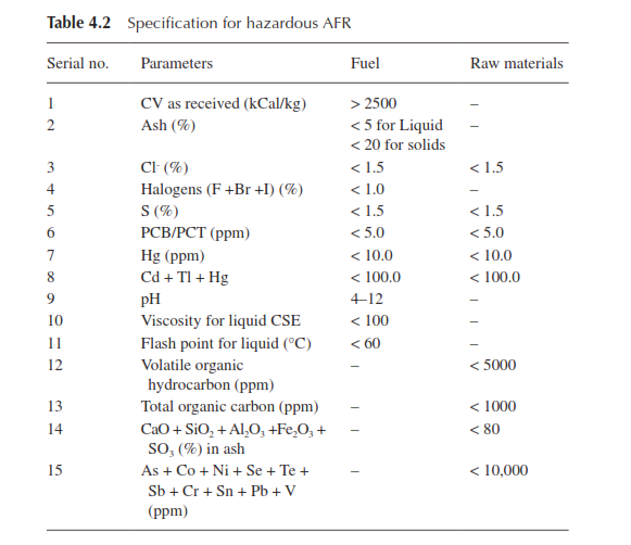
There are recommended standard tests to determine the above prop-erties in various national and international standards and guides. The Central Pollution Control Board in India, in its guide of February 2010, specified certain parameters for hazardous wastes, as given in Table 4.2.
Biological parameters in classifying hazardous wastes
Hazardous wastes can have organism-mediated chemical activity leading to infectious properties. In order to classify such materials biologically, some terminologies are used, which are briefly explained below (2):
- Bioconcentration: a process by which living organisms concen-trate a chemical to levels exceeding the surrounding environmen-tal media.
- Lethal dose (LD): a dose of a chemical calculated to expect a certain percentage of mortality in a population of an organism exposed through a route other than respiration.
- Lethal concentration (LC): a calculated concentration of a chemi-cal in air, a 4-hour exposure to which through respiration by a population of an organism will kill a certain percentage.
- Phytotoxicity: a chemical’s ability to elicit biochemical reactions that harm flora.
Based on the chemical and biological criteria mentioned above, haz-ardous wastes have been listed in three schedules in the guide of the Central Pollution Control Board in India.
Feasibility of an AFR project
There are certain basic social, economic, and technical factors to be considered for developing an AFR project for a cement production unit. Based on the experience in different countries, it appears that the impor-tance and relevance of the factors vary from country to country. While some factors become irrelevant in one situation, certain others turn out to be more pertinent in another. Keeping this in view, one may consider the following factors as generally important in the assessment of an AFR project for the cement manufacturing process:
1-availability and cost
2-source and transportation
3-characteristics, e.g., moisture, ash content, volatile matter, and calorific value
4-present mode of disposal
5-drying and grinding characteristics
6-storage, handling, feeding, and firing systems
7-ignition and combustion aspects
8-effects on kiln operation and refractory lining
9-impact on clinker quality
10-environmental and social considerations
11-economic viability
The above list is only illustrative and not exhaustive. For liquid and hazardous wastes, one will have to evaluate certain special properties as mentioned earlier. Although lowering the unit cost in cement pro-duction is the key driver when developing an AFR project at a cement plant, the feasibility study is never complete with the development of a business case with an acceptable level of capital investment, attractive return, and manageable technical risks. It has to be effectively supported by the strategies to be adopted for the health, safety, and environmental issues (3):
- odor
- noise pollution
- emissions to air
- emissions to water and land
- visual impact
- carbon footprint
- stakeholder engagement
Odor
Odor issues become important particularly with the use of municipal waste, perhaps due to residual organics that continue to break down. What constitutes an offensive odor is obviously subjective as it depends on the intensity, character, frequency, and duration of the odor. A stan-dard has been developed to attempt to deal with the issue objectively: “EN 13725:2003 Air quality – determination of odor concentration by dynamic olfactometry.” When odor risks become an issue, the approach is to undertake a baseline study at sensitive receptor sites, followed by measurements when the fuel is in use with the help of the standard men-tioned above. Various mitigation measures need to be adopted to enclose and vent the storage vessel and building, along with the treatment of the vented air. A useful alternative may also be to vent the odorous air to the inlet compartments of the clinker cooler.
Noise pollution
The noise pollution arises from increased traffic on the approach roads to the plant and also inside the plant to the storage area. The noise issue can normally be dealt with by restricting the delivery time during a day but this may have implications for the storage capacity and needs to be fully assessed during the design stage. The necessity of minimizing the interaction between the pedestrians and delivery trucks inside the plant by appropriate provision of internal roads is another important consider-ation in the design phase.
Emissions to air
Kiln emissions that are of prime concern are particulates and nitrous oxide. It is well established that particulate emissions are not dependent on the fuel being burnt. The data available also show that with firing of AF the emission of nitrous oxide may not change in most cases; in some situations, it may be reduced. However, heavy metal content in most alternative fuels is expected to be higher than in bituminous coal but it tends to be trapped during the clinkering process. Consequently, no significant impact occurs due to emission of heavy metals. Nevertheless, a comparative desk calculation is essential for emissions due to change in fuels.
Emissions to water and land
A major risk to water and land in AF storage and handling is fire and the prevalent regulations for fire hazard management in a region will apply also to the facility. Further, care must also be exercised in containing the residues, should such an incident occur. Provision should be made in the design of the storage for the containment of water and fire retardants used to quench fire.
Visual impacts
For the benefit of employees and the community it is always desirable to assess the AF storage area for its visual impact, although it may not be an imperative requirement. Key considerations are the visibility of the proposed facility, the choice of cladding materials, and the height of the facility. An important housekeeping issue is the escape of loose materials from the receiving station and spillage from the feed delivery system. A well designed and engineered storage and handling system will properly address these issues and minimize the impact.
Carbon footprint
Calculation of the greenhouse gas saving should be undertaken in accor-dance with the national technical guidelines and aggregated with the direct savings to arrive at a true greenhouse measure of the project. One such document that one may like to refer to for estimating CO2 savings is “Technical guidelines for the estimation of greenhouse gas emissions by facilities in Australia,” which provides some standard factors and methodologies. It may be pertinent to mention here that the presence of biomass in the AF will result in a reduction in carbon emissions as the CO2 emissions from materials like wood and paper are considered part of the natural carbon cycle (biogenic), unlike the emissions from coal or natural gas, which are classified as anthropogenic. This is a simple example of factors that need to be considered in estimating the green-house benefits.
Stakeholders engagement
In most situations, there are no universal processes to engage with the stakeholders, it may be useful to make a reference to the com-munity engagement document entitled “Communications and stake-holder involvement in the cement industry,” prepared by the Cement Sustainability Initiative of the World Business Council for Sustainable Development. Feedback from the surrounding community and involved stakeholders is quite important in developing an AF project. Formation of a community consultative committee may be a facilitating step in the AFR strategy (3).
Inventory and material characteristics
Although the inventory and quality of alternative fuels vary from coun-try to country and even region to region, the past use pattern globally indicates that the following types make up the major trend of application:
- municipal solid waste
- biomass
- scrap tires
- hazardous wastes
- sewage sludge
- industrial plastic waste
Based on the data available from various sources of the government of India and reported in (4 & 5), it seems that about 62 million metric tons of solid waste is generated annually in the country, of which 5.6 million metric tons is plastic waste, 0.17 million metric tons is biomedical waste,7.90 million metric tons is hazardous waste, and 0.15 million metric tons is e-waste. The per capita waste generation in Indian cities ranges from 200 to 600 g.
Municipal solid waste (MSW)
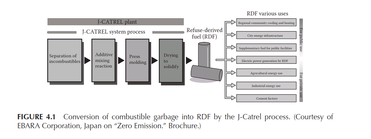
MSW is a heterogeneous mixture of daily items that people use and discard. It includes all types of biodegradable, inert, recyclable organic and inorganic waste materials. Although it has been mentioned above that 62 million metric tons of MSW is generated every year, which trans-lates into 450 g of average per capita generation, the quantity actually collected is about 42 million metric tons, out of which only 12 million metric tons of MSW is treated by the municipal authorities. It is pro-jected that by the year 2025 under the business-as-usual scenario about 140 million metric tons of MSW will be generated. MSW is made up of 9.0% plastic, 11.0% glass, 3.0% metal, 13.0% paper, 55.0% biodegrad-able materials, and 9.0% inert substance. Out of this, the entire quan-tity of plastic and paper and about 10.0% of the biodegradable materials constitute the recoverable fuel portion. Therefore, the key to achieve an efficient resource recovery is its segregation into individual fractions. The major problem in the above proposition is to find ways of using the segregated combustible fractions (SCF), which are not recyclable. These fractions may contain soiled paper, soiled cloth, contaminated plastics, packaging materials, leather, rubber, etc. Such fractions can be utilized as an AF only when they are converted into refuse-derived fuel (RDF) or solid recovered fuel (SRF) having defined quality parameters. The non-recyclable SCF is converted into SRF or RDF through a processing facility that can either be located outside or within a cement plant. A pro-cessing plant for RDF has complete facilities of appropriate screening, drying, air density separation, and further screening, blending, additive dispensation, press molding, final drying, and solidification, as shown in Figure 4.1.In this context, it may be worthwhile to make a reference to the cat-egories of RDF defined by ASTM for use in waste-to-energy plants (see Table 4.3) (6).
The above classification does not define the essential requirements of RDF suitable for cement kilns. Similarly, the classification of RDF into
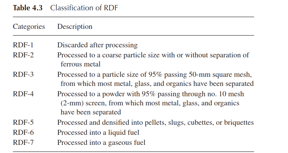
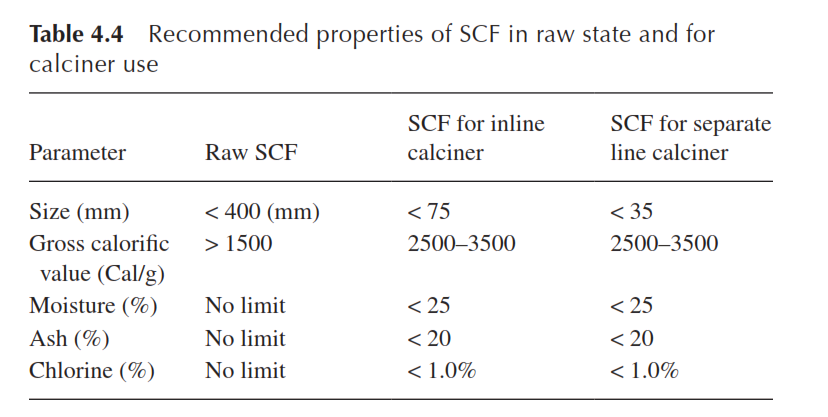
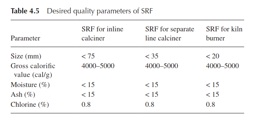
five categories in EN 15359:2011, based on CV, Cl−, and Hg contents in as-received samples is also not fully developed for the cement industry. An attempt has been made in India to specify the raw segregated com-bustible fraction (SCF) that could be converted into different grades of RDF for cement kilns. The recommended quality parameters are given in Table 4.4 and the desired specifications of the further processed fuels designated as SRF as distinguished from RDF are presented in Table 4.5 (6). It is expected that the efficacy of utilization of non-recyclable combustible materials present in MSW can be enhanced by introducing proper specifications of RDF, SCF, and SRF.
Biomass residues
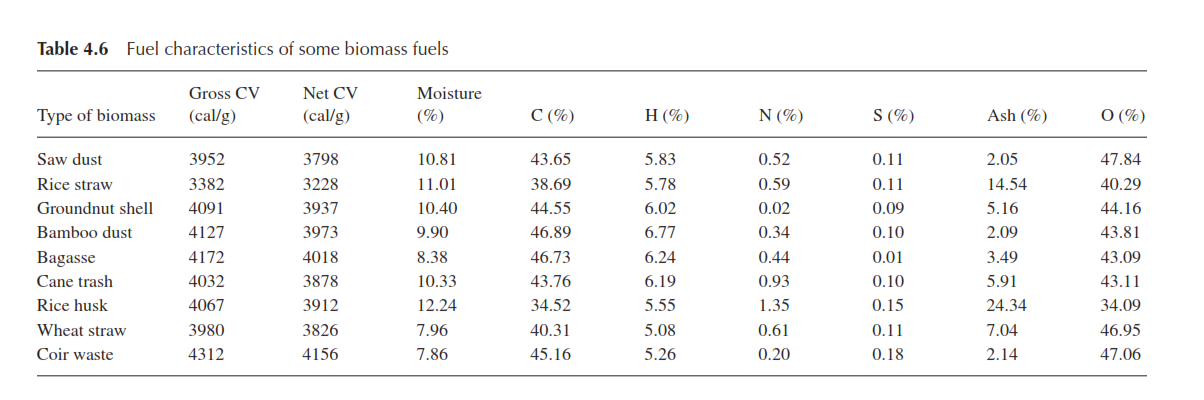
Biomass is the organic matter derived from agriculture, forestry, and living organisms. It is renewable, widely available, and carbon-neutral. Rice and paddy husk, mustard husk, bamboo dust, saw dust, food indus-try waste, wood chips, ground nut shells, coconut shell, tree bark, and straw are some examples of the materials commonly used or that can potentially serve as alternative fuel. It is estimated that about 500 mil-lion metric tons of biomass in the form of agricultural crop residues is generated in India. Since biomass is extensively used as domestic fuel, fodder, power generation, etc., the surplus available to serve as potentially alternative fuel in the cement plants may be in the range of 120–150 million metric tons per year. No prognosis has been made on its increased availability in future. A wild shrub called “juli flora,” which grows uncontrolled in barren uncultivated land, is considered as a good biofuel. It is reported that power plants are operating on wood chips of juli flora. The composition and calorific value of certain varieties of bio-mass fuels are given in Table 4.6 (7).
From the above table, it is evident that the moisture content in the biomass residues varies in the range of 7 to 11% but the moisture content in the bamboo dust may be highly variable. Sometimes the as-received sample may show as high as 30% moisture, which comes down to less than 3% on atmospheric drying. A commonly observed value is shown in the table. Along with relatively high moisture content the agricultural waste materials have lower calorific value but due to their fixed carbon content and high volatile matter they turn out to be a group of easy-burning alternative fuel. The ash content in the rice straw and rice husk is much higher than that of the other biomass residues. In one particular study (8) it was shown that mustard husk contained higher alkalis com-pared to other agricultural residues. Hence it is always desirable to make a comparative evaluation of various biomass residues in respect of their sulfur, chlorine, alkali, and ash content before use. Some of the waste materials are known to be difficult to grind and, if ground together with coal, the mill output suffers. Hence their direct feeding may be preferred and the partial substitution of coal with these wastes does not have any adverse effects on the process and the product. In countries with high agricultural base, biomass and biomass residues can technically substi-tute 5–7% of the fuel requirement of cement plants.
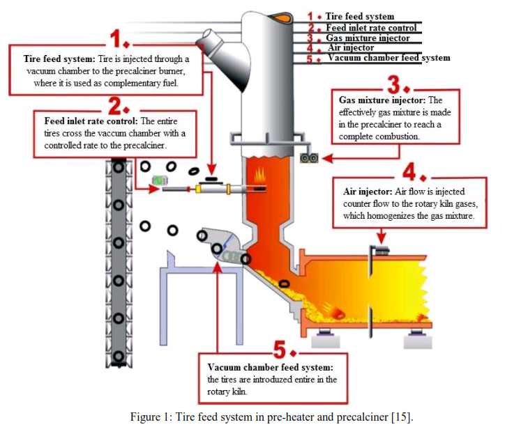
Scrap motor tires
In the cement industry, scrap tires have been used as an auxiliary fuel for a long time. In older kiln systems without preheaters and precalciners, complete tires were fed into the kiln inlet through a simple mechanism to cover a relatively large proportion of the overall fuel requirement. However, in modern kiln systems with a separate precalciner vessel and a high calcination rate, the use of complete tires via the kiln inlet is restricted to a relatively small proportion of around 5% of the overall fuel requirement. To use higher proportions in the precalciner kilns, the shredding of tires into pieces of a maximum size of 50 × 50 mm becomes necessary. As fuel, the scrap tires are characterized by a high calorific value (> 6500 cal/g), a high volatiles content (> 60.0%), a low to moder-ate ash content (7–20%), and a moderate content of harmful substances, similar to most primary fuels.
According to the Rubber Manufacturers Association, the USA dis-penses 379 million scrap tires each year, of which 52% or about 200 million pieces are burned as fuel (9). The cement industry in the USA is a very large user of tire-derived fuel. In India, according to the data of the All India Tire Manufacturing Association, 0.83 million metric tons of scrap tire was available in the year 2011–2012 and, considering a modest 5% increase per year, it is projected that the country would generate 1.32 million metric tons of scrap tires by 2025. After providing for the recycling of rubber and fuel requirement of small and medium enterprises, it is estimated that the cement industry in the country would in future have about 0.8 million metric tons of waste tire to be used as an alternative fuel.
Hazardous waste
The national inventory of hazardous waste collated by the Central Pollution Control Board in India indicates that 41,523 manufacturing units generate 7.90 million tons every year, 42% of which is used for land filling, and 50% is considered recyclable, leaving 0.60 million tons to be disposed of through incineration. This mode of disposal of haz-ardous waste does not permit gainful use of the fuel value available in the waste materials and in addition it adds to the consumption of fossil fuel and emission of greenhouse gases. It is also projected that by 2025 the availability of hazardous waste necessitating incineration will cross 1 million tons. Its use as an alternative fuel in cement kilns has therefore been approved by the authorities concerned with the provision of appro-priate emission norms.
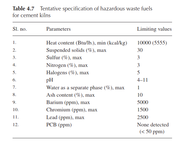
The hazardous waste materials are mostly discharged in the form of slurry or sludge from petroleum refineries and manufacturing units of dye and dye intermediates, basic drugs, benzene-based organic chemi-cals, paint and coating materials, etc. The manufacturers of printing ink, printing companies, solvent recyclers, waste oil dealers, etc., also gener-ate such wastes. Because of the proliferation of such waste materials, there has been some attempt by some pollution control authorities to draw up a guiding specification for such hazardous liquid waste fuels for cement kilns. An illustration of such a specification is given in Table 4.7.
The high calorific value related to their high volatiles content shows a great potential for this type of sludge to be used as an alternative fuel. The high sulfur content in the sludge and sludge ash may have to be taken care of through appropriate process steps.
Process-wise, the sludge samples available in semi-liquid state may be roll-pressed first to remove the water and other aqueous acidic con-taminants. The cake so obtained can be easily handled and dried in a dryer. Sludge tests have indicated that it becomes soft at 75–80°C and becomes hard on cooling to the room temperature. The sludge turns into a brittle solid on heating to about 150°C for 3–4 h, followed by cool-ing. This processed sludge can be ground and used as a pulverized fuel.
The sludge ignites at a temperature of 300°C, leaving behind a char-like material that burns at a temperature of 700–800°C. The sludge can be fed by screw conveyor along with the raw meal at the kiln inlet after dry-ing with the preheater exit gas. Alternatively, the sludge can be kept in a fluid state at an appropriate temperature and pumped into the rotary kiln through an auxiliary burner.
Sewage sludge
Of all varieties of sludge, sewage sludge, which is a by-product of urban wastewater treatment, has been used quite extensively in the cement industry and more particularly in the European countries and in the USA (10). Wastewater with a certain level of contamination and having about 5% solids in suspension, originating from residences, rainwater, and commercial establishments, is treated through processes of thicken-ing, mechanical dewatering, conditioning, and drying. The main routes of sludge disposal are landfilling, agricultural application, incineration, and dumping into the sea. The generation of the sludge about a decade back in the European Union, barring the Eastern European countries, was more than 9.0 million tons (with 10% moisture). The situation in the USA was also similar and reached 6.3 million tons of dry biosolids in the year 1998 and showed a 16% per capita increase in generation. No reliable statistics of the generation of sewage sludge in India is readily available.
The disposal modes like landfilling, dumping, and agricultural application have their own environmental compulsions and limitations. Independent incineration is an energy-intensive process. Hence, burning in cement kilns has been receiving serious attention. Sewage sludge in its original liquid form has a very high water content. Mechanically dewa-tered sewage sludge with a water content of 55–75% would be combus-tible, but, from the process point of view, this would not be preferable.
Therefore, the sewage sludge is thermally dried to form a powder or a granulated mass with residual moisture of 5–25%.
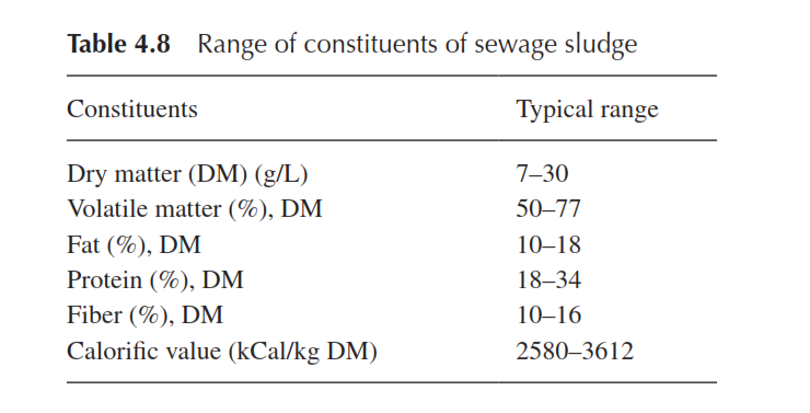
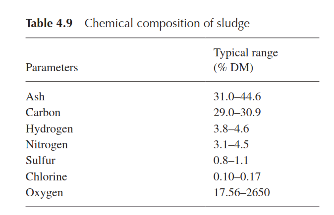
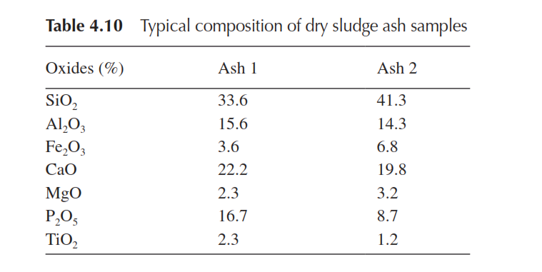
The compositional details of the sewage sludge are given in Table 4.8, 4.9, and 4.10.
Generally, the use of sewage sludge for the production of cement clin-ker is an excellent option, since the high ash content of sewage sludge acts like a secondary raw material, while the organic matter is used as fuel. Although its calorific value is low, it is possible to achieve high flame temperature. As it has high oxygen content in its composition, the stoichiometric ratio of air (kg) to heat released is quite low compared to that of high-ash coal. However, for proper evaluation of combustion of sewage sludge in cement kilns, the following parameters are important (10): P2O5, chlorine, nitrogen, and particle size. As a general rule, the P2O5 content in clinker should not exceed 0.5% as with higher concen-tration, the belite phase tends to increase. The chlorine content in the raw meal should be lower than 0.015% for avoiding the installation of a bypass system in the kiln. The total nitrogen content in the dried sludge in the form of nitrates and ammoniac can reach up to 8.0% of dry mat-ter, which is significant and cannot be ignored for evaluating the pos-sible effect on NOx emission. The particle size of the sludge is important for both pneumatic transport and burning. Taking all these parameters into consideration, it is estimated that the theoretical substitution rate for sewage sludge would lie in the range of 0.10–0.17 kg sludge/kg clinker.
Sewage sludge with high mercury content may be problematic for the process. Since this element is highly volatile, it is not arrested in clinker. Instead, mercury is enriched in the external circuit between pre-heater and dust capturing facility. In this case, the emission of mercury is avoided by not recirculating the dust.
Industrial plastic waste
It is tentatively estimated that at least 100,000 tons of plastic waste are generated every day in India. Plastic waste that cannot be recycled can be used in cement kilns. The problem often encountered for use is the non-segregation of the plastic waste from other waste. Industrial plastic waste is particularly available from the waste paper-based paper mills, which have 1–2% plastic waste in wrappings, laminations, covers, and so on. It is also available in the form of discarded packaging bags, drums, etc. from various manufacturing units.
Miscellaneous alternative fuels
Apart from the categories described above, there are several other sources of alternative materials. A few such types are illustrated below.
- Meat and bone meal. Since in the European countries there is a prohibition of using meat and bone meal (MBM) in agriculture, new disposal methods have had to be found for the huge amount of material that is generated. Similar to other alternative fuels men-tioned earlier, use of MBM as an auxiliary fuel in the burning process of cement clinker is a very good possibility for disposal and utilization. Animal meal is characterized by a relatively high calorific value and a high content of volatiles, but at the same time, the high levels of chloride and phosphate (see Table 4.1) have to be given due consideration in respect of the process and cement quality.
- Spent pot-liners. Spent pot-liners from the aluminum industry present another potentially valuable fuel resource. It is estimated that approximately 650,000 t/y of spent pot-liners are available globally. Their use had not been popular in the past due to the apprehension of fluoride and cyanide residues. The presence of sodium may also discourage use.
- E-Waste. Discarded electronic waste is the fastest-growing stream of waste in industrialized countries. This trend is also evident in India and the opportunity to use this waste as an alternative fuel is being explored. The E-waste Rules were introduced in India in 2011 and were made effective from May 2012. There are 128 producers in 11 states, with 34 authorized e-waste collection centers in 19 states.
Systematic quality assessment
A systematic quality assessment scheme is essential to enhance the use of alternative fuels. Any such scheme is formulated with the following broad objectives:
- To handle a multiplicity of waste streams
- To differentiate hazardous from non-hazardous waste
- To obtain reliable test results with both precision and accuracy
- To know the ground state of contaminants and their environmental reaction potential
- To assess the risk of exposure to contaminants
The plan for essentially non-hazardous AFR assessment requires both a system and certain facilities. The system is focused on bulk sampling; the preparation of samples; proximate analysis; the measurement of chlo-ride and sulfate contents, ultimate analysis, ash composition, calorific value, grinding behavior of solid fuels, particle size distribution, and igni-tion property; and the safety and precautionary measures to be adopted in handling the materials. For the sampling of agricultural waste, tire chips, MSW, industrial waste, rubber waste, etc., one may follow the pro-cedure laid out in CEN/TS 15442. A minimum of 24 samples are to be drawn. For a typical supply of 60 trucks, it is preferable to plan sampling in two groups of 30 trucks each. One sample may be drawn from every two trucks, the selection of trucks being random. In order to prepare the analytical samples from MSW and agricultural waste it is essential to treat them in liquid nitrogen, to use a Fritsch mill, and to pass the mate-rial through a 500-μm screen. It is necessary to preserve the samples in sealed containers. For other fuels received in the form of powder or sludge it is essential to prepare the test samples in a dry state passing through a 212-μm screen. For chemical analysis of the properly prepared samples it is preferable to use thermo-gravimetric instruments and for ultimate analysis the facility for CHN&S determination is recommended. To determine the ash composition, it is advisable to use an elemental ana-lytical instrument like the X-ray fluorescence spectrometer.
Measurement of organic pollutants
The measurement of the following eight organic pollutants is important for the cement industry:
- Non-methane volatile organic compounds (NMVOC)
- Dioxins and furans—polychlorinated dibenzodioxins (PCDD) and polychlorinated dibenzofurans (PCDF)—both expressed as a toxic equivalent 1-TEQ
- Polychlorinated biphenyls (PCB)
- Anthracene
- Benzene
- Naphthalene
- Bis (2ethylhexyl) phthalates (DEHP)
- Polycyclic aromatic hydrocarbons (PAH)
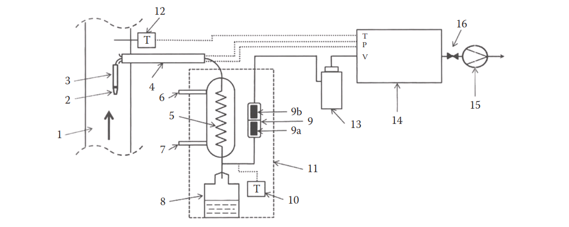
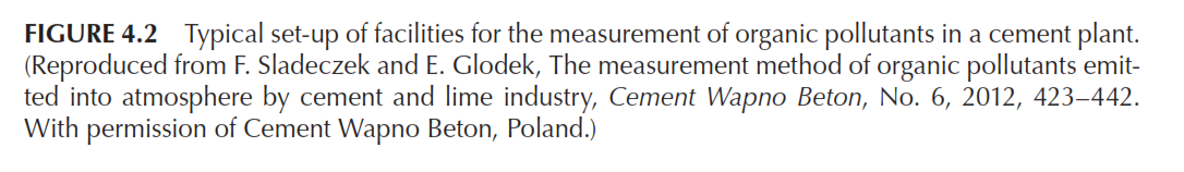
In some countries, it is mandatory to measure and report these pollut-ants in exhaust gases at least once a year. In many other countries they are not measured, neither do they have emission benchmarks. The European Pollution Release and Transfer (E-PRTR) data or the data from the US Environmental Protection Agency (EPA) are primarily relied upon. A study has been reported for the gas sampling and analysis of the above eight pollutants (11). The set-up used for isokinetic gas sampling is shown in Figure 4.2. Depending on the mode of capturing of the pollutants, some changes in the gas sampling set-up were made. The sampling methods and measurement procedures are summarized in Table 4.11.
The results of the measurements showed that the emission of NMVOCs, DEHPs, and benzene were close to E-PRTR annual emis-sion limits, which are 100,000, 10, and 1000 μg. The rest of the pollut-ants comfortably met their annual emission limits, viz., 0.0001 μg for PCDDs and PCDFs, 0.1 μg for PCBs, 50 μg for anthracene, 100 μg for naphthalene, and 50 μg for PAHs. It should also be borne in mind that the benchmark emission parameters for the organic pollutants are not always available in different countries and they need to be developed for their effective monitoring and control.
Requirements of test facilities
Considering the multiple streams of alternative fuels, including the haz-ardous varieties that an assessment laboratory has to be equipped to handle, its overall preparedness depends not only on the capability of on-site measurement of the critical organic pollutants as described above but also on the ability to conduct special tests on toxicity and several other parameters. The overall facility requirements can be tentatively summarized as follows:
- Proximate analysis
- Ultimate analysis
- Elemental determination (Cl, F, Pb, Cd, As, Hg, Cr, Co, Ni, Th, Cu, V, Sb, Mn, Se, Fe)
- Measurement of total organic carbon (TOC)
- Toxicity characteristics leaching procedure (TCLP)
- Total petroleum hydrocarbons (TPH)
- Organo-chlorine compounds
- Volatile organic compounds (VOCs) and semi-VOCs
- Polychloro-biphenyls (PCBs) and phenols (PCPs)
- Calorific value—gross and net
- Particle size determination (PSD) and particle flow characterization
- Viscosity of liquid waste
- Water content in liquid waste
- Solid content in liquid waste
- Hardgrove grindability tester
It should be borne in mind that environmental science and engi-neering are relatively young professions compared to other disciplines and depend heavily on both inorganic and organic chemistry. There have been rapid advances in analytical and characterizing tools for complex hybrid materials that one comes across in environmental chemistry. In moving towards reliable assessment of intrinsic qual-ity of waste fuels and their emission impacts, it is important to be prepared with both unconventional expertise and advanced tools for sampling, sample preparation, analysis, and testing, as well as on-site measurements.
Co-processing of alternative fuels
Co-processing refers to the utilization of suitable waste material in the manufacturing process for the purpose of energy and/or resource recov-ery and resultant reduction in the use of conventional fuels and/or raw materials. The clinker and cement manufacturing system has certain operational features that make it eminently suitable for co-processing of AFR.
Advantages of cement kilns
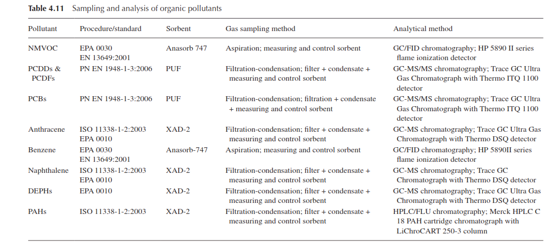
Cement kilns have proved to be one of the best incinerators, which burns the waste at a high temperature of about 1400°C and which has long residence time in the combustion zone, unlike the normal incinerators. A comparison of combustion zone conditions in a cement kiln and an incinerator is given in Table 4.12.
In cement kiln systems, the ignition and burn-out behavior of alterna-tive fuels is essentially influenced by particle size, moisture, ash content, and the content of volatiles. Particle size and moisture can be directly influenced by the kind and degree of processing, while the contents of ash and volatiles cannot be changed.
Cement kilns are generally suitable for the safe destruction of most types of hazardous and toxic organic material. It is generally consid-ered that all organic compounds are adequately destroyed if exposed to a temperature of 1200°C for a residence time of two seconds under oxidizing conditions. The conditions in the burning zone of cement kilns exceed these requirements by a wide margin. Cement kilns further show a high degree of turbulence in the burning zone and a high thermal sta-bility, which is a function of their large size and the amount of heated material in the kiln. Thus, even if a cement kiln is forced into an emer-gency shutdown, all hazardous material in the kiln should be completely destroyed, provided that automatic cut-offs prevent further injection of such material.
In addition, cement kilns operate under alkaline conditions. This means that, provided the rate of input of acidic precursors is controlled so as not to overload the system chemistry, all acidic gases such as HCl, SO2, H2SO4, and HF generated during burning are either absorbed by the kiln charge or combined with the kiln dust in the form of harmless inorganic salts. A portion of these salts is generally acceptable in the clinker, while an excess may have to be discarded as kiln dust or bypass dust.
Metals are not destroyed in the burning process, although most of them are trapped in the clinker and in the collected dust. Materials containing significant quantities of heavy metallic constituents including lead, arsenic, mercury, cadmium, chromium, and thallium are not candi-dates for burning in cement kilns. Other metals, such as those typically found in soil (silicon, aluminum, iron, magnesium, calcium), constitute the bulk of the ash from the combustion of hazardous organic materials and are readily absorbed in the cement product since they are primary constituents of cement.
The hazardous materials, whether in gaseous, liquid, solid, or sludge form, must be introduced into the kiln at a point where the above-mentioned time-temperature conditions can be met. This means that the gas must be maintained at a minimum temperature, for a period of at least two seconds from the point of introduction. This minimum tem-perature is a function of the hazardous material; it is 1200°C for mate-rials containing polychlorinated by-phenyls (PCBs); it can be lower for other materials. Emissions of carcinogenic substances should be limited to the largest possible extent by giving consideration to the principle of production.
It is therefore essential that the waste treatment and objectives of use must be coordinated with regard to process engineering and quality. Solid substitute fuels with an average lump size of 250–80 mm to be fed via the kiln inlet or a calciner of a rotary kiln are processed differ-ently. In actual practice, there are two groups of alternative fuels. The first group is characterized by high to very high contents of volatiles and requires less grinding. Mostly, rough shredding (< 30 mm) is sufficient to ensure the desired combustion behavior. Unfortunately, these fuels are often inhomogeneous and difficult to handle. The other group of second-ary fuels, like petroleum coke from oil refining or spent pot-liners from aluminum production, have lower reactivity (due to their low content of volatiles). Therefore, similar to anthracite, these fuels have to be ground very finely (< 5% residues on 90 μm) to enable sufficient burn-out at the calciner or sintering zone.
The grinding technology for many solid substitute fuels is still in an evolving stage. It seems that the operating principles of the Vertex mill, originally designed for grinding food articles, can also be used success-fully for grinding solid substitute fuels. Depending on the grinding resis-tance, reduction ratios of up to > 100:1 are possible.
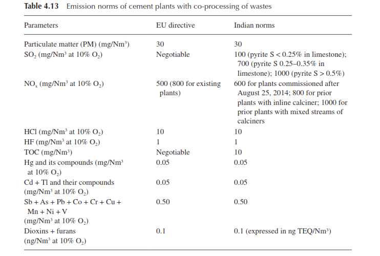
Co-processing is an approved activity in India and the Environment (Protection) 3rd Amendment Rules 2016 have defined the mandatory emission norms for cement plants operating with alternative fuels, which are briefly presented in Table 4.13, along with the EU Waste Incineration Directive (12).
Systemic requirements for using alternative fuels
A pre-processing industry has sprung up in some countries to manage and broker various waste streams from numerous generating sources, which has boosted up the use of alternative fuels in those countries. Some of the cement plants have also set up integrated pre-processing plants in order to adopt the AFR strategy more effectively. The inter-face of the waste management and recycling industry with cement plants along with the facilities required there is shown in Figure 4.3 (13). The pre-processing industry has to be more alert and concerned with the mapping of waste material sources and needs to have an efficient infra-structure for collecting the waste materials, which can be treated at those units by undertaking operations like sorting, crushing, shredding, blend-ing, pressing, etc. Mostly the business aim of this industry is to produce SRF or RDF with consistent quality parameters acceptable to the cement production units. It is also feasible to make the pre-processing plants capable of producing solvent fuels that are produced by blending dif-ferent liquid wastes with strict specifications on water content, heating value, and viscosity. Once prepared to required specifications, the solid or liquid fuels are transported to cement plants for safe storing, handling, and burning without any adverse environmental and health issues for the employees or to the community.
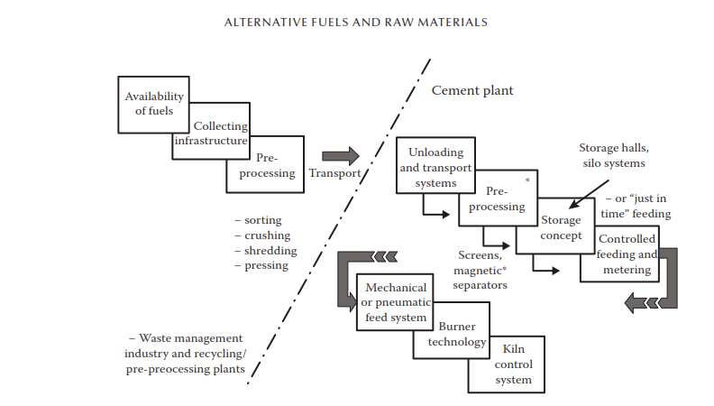
FIGURE 4.3 Interface between the waste management and recycling industry and the cement plants. (Reproduced from Cement International, Storing, metering and conveying solid secondary fuel—Design basis and equipment, Cement International, Vol. 5, 6/2007. 43–53. With permission from Cement International and Schenck Process GmbH.)
Storing, dosing, and conveying
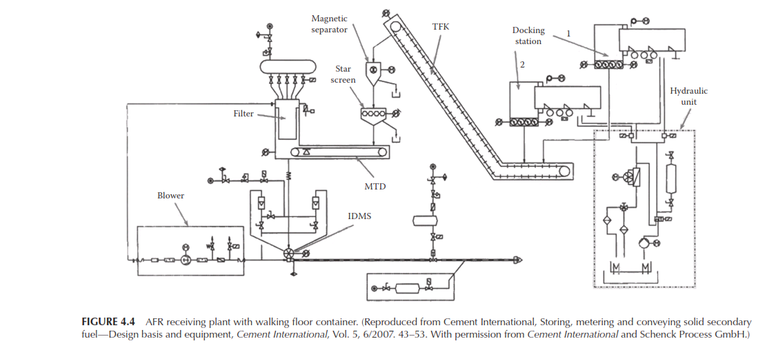
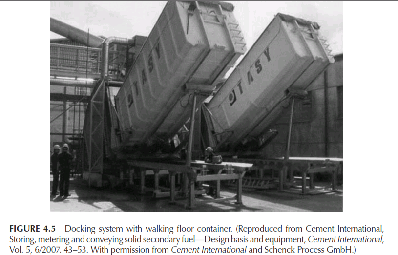
Specially designed installations are required to control the use of waste from its arrival at the plant to its entry into the kiln. These comprise stor-age systems, dosing systems, and conveyance systems to the kiln. Designs vary depending on the characteristics of the alternative fuel used and the space available at each plant. The manner in which the product is received and stored on its arrival and the way in which it is put in the kiln will therefore have to be adapted to the plant in question. However, certain basic features are common to all plants (13,14). The AFR receiving system and the docking station are illustrated in Figures 4.4 and 4.5, respectively. There are, however, two types of installations: fixed and mobile. Further, each installation, fixed or mobile, comprises four basic sections:
-Waste storage
- Storage yard with pit
- Receiving hopper for unloading trucks with dump trailer
- Receiving hopper for unloading trucks with moving floor trailors
- Silo
-Conveyance to the dosing station
- Single-rail hoist block with longitudinal movement or bridge crane with transverse and longitudinal movement, both with grab bucket
- Mechanical conveyor
-Dosing station
- Mobile or fixed station of modular design
- Fixed station in one module
-Conveyance to the kiln
- Pneumatic conveyance
- Mechanical conveyance
Additionally, two other factors must be considered when designing an installation:
- Dosing of tires and whole large packages
- Automation and control
Some of these installations are elaborated below.
Storage yard with pit This is a rectangular yard approximately 4 or 8 m wide by 14 m long, with a pit 4 m deep, into which the trucks unload directly. This type of yard offers a large storage capacity that is clean and simple, as all the material remains inside the pit below the ground level of the plant.
For a storage yard 8 m wide, a bridge crane with longitudinal and transverse movement is used to allow the collection of material at any point on the yard. For a yard 4 m wide, a hoist block with only one direc-tion of movement—longitudinal—is usually used. The operating results are the same as for the 8m yard, but only half the storage capacity is avail-able. Both systems incorporate a hydraulically operated “octopus”-type grab bucket to carry the product in successive loads to the dosing unit.
The dosing station is situated at one end of the yard, usually under a receiving hopper into which the grab bucket drops its load and under which a belt weigh feeder is installed. The dosed product is discharged onto a conveyance system going to the kiln, which may be pneumatic for particle sizes less than 30 mm, and mechanical for larger particle sizes. If two alternative fuels are to be metered simultaneously, or one is to have a fixed supply and the other variable, a wholly symmetrical inline yard may be built, with a double-dosing system and sharing the same bridge crane and conveyance system to the kiln.
The storage yard and pit solution is ideal for all alternative fuel types, up to a maximum particle size of 100 mm.
Silo storage systems It is well-known that silos permit large storage capacities because of their vertical configuration. They are suitable for products with small particle size and also for powdery and easily extractable products, such as sewage sludge, animal meal, etc. However, for some materials, such as animal meal, the silo and its conveyance system need to be specifically designed to suit material characteristics, especially with regard to their efficacy of extraction.
One of the main advantages of using silos for the storage of pow-dery products or products with a very small particle size is that filling can be done by pneumatic conveyance. Another advantage is that the entire material can be fed to the dosing station completely in line by gravity, thus saving mechanical conveyance and simplifying the installa-tion. This system is therefore preferred for powdery products or slippery products with a very small particle size. The flow sheet for silo storage is given in Figure 4.6.
Dosing and conveyance to kilns The best dosing system for alterna-tive fuels is the belt weigh feeder, mainly because most of these fuels have a low density and so it is necessary to work with a large volume of load per meter. Depending on the type of fuel to be used, the belts may be made of rubber or synthetic material, with special characteris-tics such as greaseproofing if necessary. When pneumatic conveyance is used to send the dosed product to the kiln, a layer breaker is installed at the belt weigh feeder’s outlet, which breaks up the layer of dosed mate-rial so that it does not fall into the conveying hopper in large lumps, thus ensuring a more even feed to the pneumatic conveyor.
The pneumatic conveyance to the kiln’s burner usually includes the following components:
- Input hopper into the pipeline.
- Rotary valve, connected directly to the dosed product inlet hopper, for feeding the material to the pneumatic conveyance piping. Vertical pitch is generally preferred as conveying air cleans the rotor.
- Conveyor piping, through which the product is sent to the kiln’s burner. The pipe dimensions are calculated with respect to the size of the dosed product, the flow rate, the length of the conveyance, and any bends that may be present on the route.
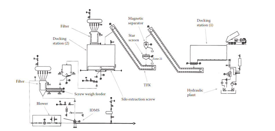
FIGURE 4.6 AFR storage silo in a plant. (Reproduced from Cement International, Storing, metering and conveying solid secondary fuel—Design basis and equipment, Cement International, Vol. 5, 6/2007. 43–53. With permission from Cement International and Schenck Process GmbH.)
- Instrumentation for controlling the pneumatic conveyance, such as pressure converters, pressure switches, and pressure gauges distributed at different points along the route for full pressure monitoring.
- Roots blower for pneumatic conveyance by thrust—triple-lobe for an air flow rate of about 10 m3/min with a maximum thrust pres-sure of 1 bar.
- Soundproof cabin. The noise generated by a blower of these char-acteristics is 91 dBA, so it must be mounted in a closed room or a soundproof cabin. Using such a cabin made of steel and insulated with fiberglass, the perceptible noise level drops to 74 dBA. To prevent the blower overheating, the cabin usually includes a fan.
- A maximum particle size of 30 mm to permit problem-free pneu-matic conveyance.
Mechanical conveyance of the dosed fuels to the kiln mainly depends on the particle size of the product and sometimes on the kind of material. As particle sizes of over 30 mm may cause problems in pneumatic con-veyance, mechanical conveyance is in practice for larger particle size, up to approximately 100 mm. If the mode of conveyance is mechanical, the point of insertion in the kiln system normally changes to the precalciner or the preheater. This type of mechanical conveyance entails far higher investment cost than pneumatic conveyance, as it has to raise material several meters from the point of reception to the point of delivery. To avoid false air entering into the process, a double or triple gate is used at the material’s entrance to the precalciner. When the dosing system is not in operation, the gate remains completely closed. The mechani-cal conveyance comprises different equipment depending on the specific needs of the plant, and may include belt conveyors, worm screws, apron conveyors, chain redlers, bucket elevators, and so on.
Dosing of tires and whole large packages For the installation to dose whole tires, or whole pressed bales of other products such as textiles, plastic, or any other waste with an approximate volume of 0.6 to 0.8 m3, the facility that needs to be created for reception and storage of the fuels as well as for handling and conveyance up to the point of delivery in the precalciner or preheater turns out to be expensive. The dosing and kiln-feed system comprises two components. The first is a rubber belt or roller conveyor 6–8 m long and 1 m wide, which receives the package or tire from a preceding storage and conveyance system. The width of the belt can generally convey packages of up to 800 mm in width, and it has the necessary control devices to ensure that two packages do not enter the weighing system at the same time. The second is a weighing conveyor of approximately 1000 × 1000 mm with a weighing platform mounted underneath it, and a nominal capacity equivalent to the heaviest expected working weight. When working with whole tires or compact bales of fuel, the control system calculates the time in which a tire has to be unloaded into the kiln, depending on the weight measured beforehand and the flow rate set accordingly.
Automation and control The level of automation required in each installation will determine the rest of the control components, such as level reading and full mapping of the work area, grab load detection, communication between the fixed system and the mobile system, man-agement of the safety interlocks for access to the warehouse, communi-cation with the central control system, etc.
Precalciner design considerations
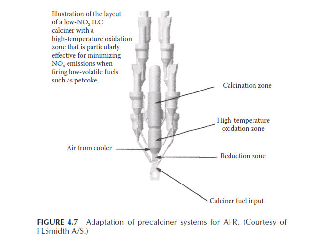
The design of precalciner systems for burning alternative fuels is essen-tially influenced by NOx and CO formation within the combustion pro-cess. It is understood that the NOx generation is related to the content of volatile matter and nitrogen in the fuel. There is a strongly decreasing trend of NOx generation in precalciners when the volatiles content in the fuel increases. Further, it has also been observed from the compara-tive burning behavior of anthracite and petroleum coke that anthracite gives rise to lower NOx generation despite its lower volatiles content, primarily due to its lower nitrogen content (12). Further, it is also known that precalciner design and atmosphere for burning significantly influ-ence the NOx emissions. Generally speaking, an inline calciner operated with a high-temperature oxidation zone yields lower NOx emission than a separate-line calciner. It is also observed that with regular designs of precalciners, while it might be possible to meet the NOx emission limit of 600 mg/Nm3 at 10% O2 with high-volatile fuels, without secondary reduction measures, it is unlikely to achieve this performance when fir-ing a low-volatile fuel like the petroleum coke. Hence, in order to deal with various streams of secondary and waste fuels, a multistage combus-tion system has become popular for NOx control (Figure 4.7).
Illustration of the layout of a low-NOx ILC calciner with a
high-temperature oxidation zone that is particularly effective for minimizing NOx emissions when firing low-volatile fuels such as petcoke.
For some of the secondary fuels that are not sufficiently prepared and ground, the precalciner path needs to be extended for more retention time to ensure complete burnout. For very coarse secondary fuels, there are two other options. An ignition chamber is a special module for burning fuels with poor ignition properties like coarse petcoke and anthracite. It is integrated in the pure air side of the precalciner. A hot-spot burner creates a zone of high temperature (1000–1200°C) and the burnout hap-pens in the extended calciner. A combustion chamber is the appropriate solution to burn very coarse fuels, for example, petcoke or anthracite ground to > 9% residue on 90 μm, as well as other lumpy secondary fuels. These fuels can be fed into the hot core zone of the combustion chamber at temperatures of greater than 1200°C. The partly burnt-out fuels are fed directly to the calciner, where they are lifted up with the gas stream and are fully burnt out in the calciner. A small amount of fuel particles may fall down in the inlet chamber and burn out in the kiln.
Use of a special combustion device “hotdisc,” designed by major equipment supplier FLSmidth and already in operation in some plants, is an appropriate example in this regard. It is a refractory-lined special com-bustion chamber that is integrated with the precalciner system (Figure 4.8). The heavier and lumpy alternative fuels burn on the hotdisc table and residence time can be adjusted for different alternative fuels. Only the burnout ashes fall into the kiln inlet and are incorporated in the clin-ker. It is also energy efficient as it operates on recuperated process heat.
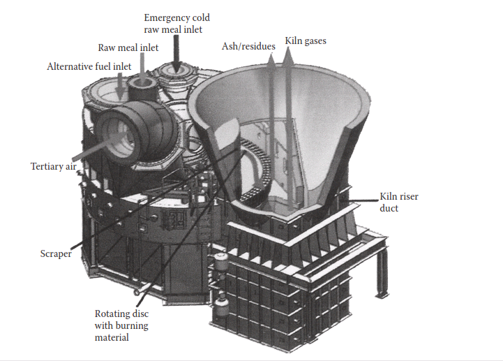
FIGURE 4.8 “Hotdisc” combustion for AFR. (Courtesy of FLSmidth A/S.)
Gasification technology
Modern gasification systems are designed to convert carbon-containing materials into a synthetic gas predominantly containing CO and H2, which finds use in power generation or as a fuel for heating and burn-ing purposes. Coal gasification processes differ widely but the three basic reactor technologies are the moving bed, the fluidized bed, and the entrained- flow gasifier (15). The moving-bed gasifier is operated counter-currently with steam and oxygen at temperatures much below the occurrence of slagging in coal (~ 550–600°C). Since this reactor design cannot gasify all types of coal, viz., the caking variety, a high-temperature slagging reactor has also been developed on similar design principles. A fluidized-bed gasifier is a back-mixed reactor in which coal particles in the feed are well mixed with coal particles already undergoing gasification. The gasifier operates at atmospheric pressure and moderately high temperatures (say, 1000°C). However, in this type of gasifier, significant amounts of unreacted carbon are lost both in the product gas and the discharged ash. Hence, this kind of gasifier is more suitable for highly reactive coal and in Germany it has been used for gasifying lignite. For higher operating temperatures, the fluidized-bed reactors produce less impurities than the conventional moving-bed gas-ifiers. The third type, i.e., the entrained-flow gasifier, is a plug-flow sys-tem in which coal particles react concurrently with steam and oxygen at atmospheric pressure. The reactor operates at higher temperatures than the fluidized-bed type and the residence time of coal particles is only a few seconds. The product contains almost pure CO and H2 and hardly any methane and higher hydrocarbons, which are present in the moving-bed and fluidized-bed gasifiers. Hence, the cold gas efficiencies of the gasifiers are different.
While gasification technology in various forms has been in com-mercial use for quite some time, the first industrial-scale gasifier for a cement kiln precalciner system was successfully commissioned just a few years ago in Switzerland. The technology is now coming of age in the cement industry and shows high promise for the future. A gasifier design for the cement industry is shown in Figure 4.9 (16).
Use of tire-derived and other secondary fuels through gasification
Tires are already in widespread use in the cement industry but for opera-tional convenience they are shredded before use. The key advantages for the gasifier system are that whole tires can be fed to the reactor without shredding and the proportion of substitution may rise to 40% of the over-all fuel requirement.
The tires are taken from storage via a conveying system and metered into the gasifier through a special feeder/airlock (see Figure 4.10). A spe-cific amount of tertiary air is diverted before the calciner into a bypass duct and injected into the reactor vessel. Inside the reactor, under reduc-ing conditions the tires are decomposed to a gas, wire, and residual coke. The product gas leaves the gasifier via the product duct and is burnt in the calciner. The solids are transported out of the reactor via a dis-charge system. The heavier (wire) components fall through to the kiln inlet where they are fused and eventually incorporated into the clinker as they pass through the kiln. The lighter coke particles are entrained in the gas stream and flow into the calciner, where they burn out together with the product gas.
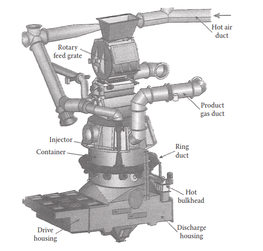
FIGURE 4.9 Coal gasifier for a cement kiln. (Reproduced from Mark S. Terry, Indian Cement Review, Part I, April 2005, 13–18 & Part II, May 2005, 15–20. With permission.)
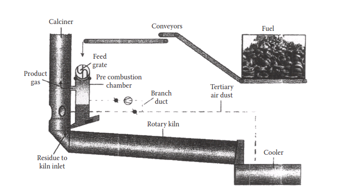
FIGURE 4.10 Waste tire gasifying system. (Reproduced from Mark S. Terry, Indian Cement Review, Part I, April 2005, 13–18 & Part II, May 2005, 15–20. With permission.)
Although the gasifier had its first success with tires, it can be designed for a broad range of alternative or secondary fuels that are available in lump form. Depending on local availability and economics, it is techni-cally feasible to utilize a variety of potential waste materials such as carpet scraps, vinyl upholstery, industrial rubber waste, or plastic car components. This development may also unfold an opportunity to supply synthetic gas to the main burner. It also opens up the opportunity of more efficient use of materials such as hazardous oil-bearing secondary materials from the refining industry, municipal sewage sludge, hydrocarbon-contaminated soils, and chlorinated hydrocarbon byproducts, all of which have already been used successfully in the gasification process. The challenge of the future is to further develop those systems and adapt them to the cement manufacturing process. This is especially encouraging since many of these materials already have acceptance within the cement industry.
Alternative raw materials
In recent years, cement manufacturing has successfully made use of a number of wastes and byproducts as supplementary raw materials. Typically, these materials are lime-bearing carbonates, paper sludge, lime waste from water purification plants, sludge from sugar and fer-tilizer industries, slag from metallurgical plants, coal ash from power plants, red mud from the aluminum industry, mineral and ore tailings from the mining industry, catalyst fines, sludge from sewage and effluent treatment plants, foundry sand, etc. Depending on their composition and characteristics they supplement different natural raw mix components. As a result, they help conserve natural raw material resources on one side and recycle the polluting industrial wastes on the other. A detailed treatise on the subject is given in (17).
Some of the major industrial wastes in India, which could find use in cement industry, are:
- Lime-rich sludge from paper pulp, sugar, ammonium fertilizer, and calcium carbide plants, estimated at about 5–6 million metric tons per year.
- Fluoride-bearing sludge and mining rejects amounting to about 0.5 million metric tons per year.
- Red mud from the aluminum industry, estimated at about 0.2 mil-lion metric tons per year.
- Blending components for cement grinding, such as fly ash (about 200 million metric tons per year) and blast furnace slag (about 10 million metric tons per year).
- Steel slag, amounting to about 20 million metric tons per year.
Of the above wastes, the lime-rich sludge from the paper, sugar, fertil-izer, and carbide industries generally has CaO content as high as 75–77% on a loss-free basis and, consequently, has the potential of substituting expensive higher grades of limestone in raw mix; further, due to the fine powdery nature of these wastes they contribute to increased throughput of the raw mill and improved burnability of the kiln feed. However, the carbide sludge and the fertilizer sludge contain high sulfate, which lim-its their use as a raw mix component. The fluorine-bearing wastes may act as effective mineralizers, if the compatibility and benefits of using them with the main raw materials of the cement plant are established through trials in the laboratory and in the plant. Wastes like red mud, fly ash, iron and steel slags, etc. can be used as corrective materials, although fly ash and granulated blast furnace slags are more effectively used as mineral additives in producing finished blended cements. The major areas of concern in using the alternative raw materials are their economic and pollution-free transportation, storage, and feeding in the production process.
Summary
From the perspectives of both energy conservation and pollution abate-ment, the use of alternative fuels and raw materials (AFR) has emerged as an important operational strategy in the cement industry. The alter-native fuels and raw materials can be classified as incombustible and combustible. The latter is further classified as industrial and agricultural. The industrial wastes are subdivided into non-hazardous and hazardous varieties. The AFRs are available in different physical states and forms. They can be gaseous, liquid, and solid ranging from powders to lumps.
The hazardous wastes are identified on the basis of their corrosivity, ignitability, reactivity, toxicity, and certain biological criteria. There are standard procedures and guidelines for testing and characterizing the hazardous wastes.
For effective use of AFRs it is essential to study the feasibility of the project which includes source mapping, quality evaluation, operational issues like odor, noise, emission, and several other parameters, engage-ment with stakeholders, processing options, and viability.
The waste streams are numerous but the more abundant ones on which the implementation of the strategy depends in India are the municipal solid waste (MSW), biomass or agricultural residues, scrap tires, hazardous wastes that are neither recycled nor used in landfilling, sewage sludge, organic solvents, spent pot-liners, meat and bone meal, plastic wastes, electronic wastes, etc. All the AFRs have different prop-erties and composition. Hence, a systematic quality assessment of the materials is essential, for which proper sampling, adoption of standard test procedures, and the use of appropriate analytical instruments are necessary. For the emission of organic pollutants, the benchmark values need to be collated by conducting field measurements in plants.
Co-processing of alternative fuels in cement plants has been approved by the environmental authorities in India and the emission norms for the plants using alternative fuels have been enforced. The emission norms are comparable with those in some of the other countries.
There are special infrastructural requirements for using alternative fuels. These include collection and supply, storing and dosing, burning in precalciners and kilns, and special environmental protection mea-sures. The basic design considerations for such installations have been briefly discussed in the chapter.
The potential of adopting the gasification technology for more effec-tive use of alternative fuels has been dealt with. The technology has had a successful trial in Europe and holds high promise as a viable option.
There are a large number of industrial wastes that are being used or have the potential of being used as supplementary raw materials in cement plants. This kind of application is obviously different from the use of wastes as fuel. The practice and potential have been indicated in this chapter. The use of granulated blast furnace slag and fly ash has not been covered here, as these byproducts have been dealt with elsewhere in the book.
The use of alternative fuels is a progressively increasing measure in the industry but the strategy has been to respect the “waste hierarchy” as defined below:
- Waste should be used in cement kilns if and only if there are no better methods for its ecological and economical recovery and recycling.
- Additional emissions and negative impacts have to be avoided.
- The quality of cement must remain unchanged as compared to products made with conventional fuels.
- The use of alternative fuels should be an integral part of waste management and should be in line with the national and interna-tional norms.
References
Robert Matha i, Calciner technology for secondary fuels, Indian Cement Review, April 2005, 21–26.
Dan i el A. Vallero, Environmental Contaminants: Assessment and
Resource Company (Australia), Successful AF implementation,
Ulhas Par li kar, P. V. K i ran Ananth, K. Murali k r ishnan,
https://en.wikipedia.org/wiki/Waste tires, retrieved on July 29, 2017.
Cement Production Technology Principles and Practice Anjan Kumar Chatterjee
Attention : click here to Download Most Important books + manuals + excel sheets + formulas + everything you should know in Cement industry , CLICKHERE NOW