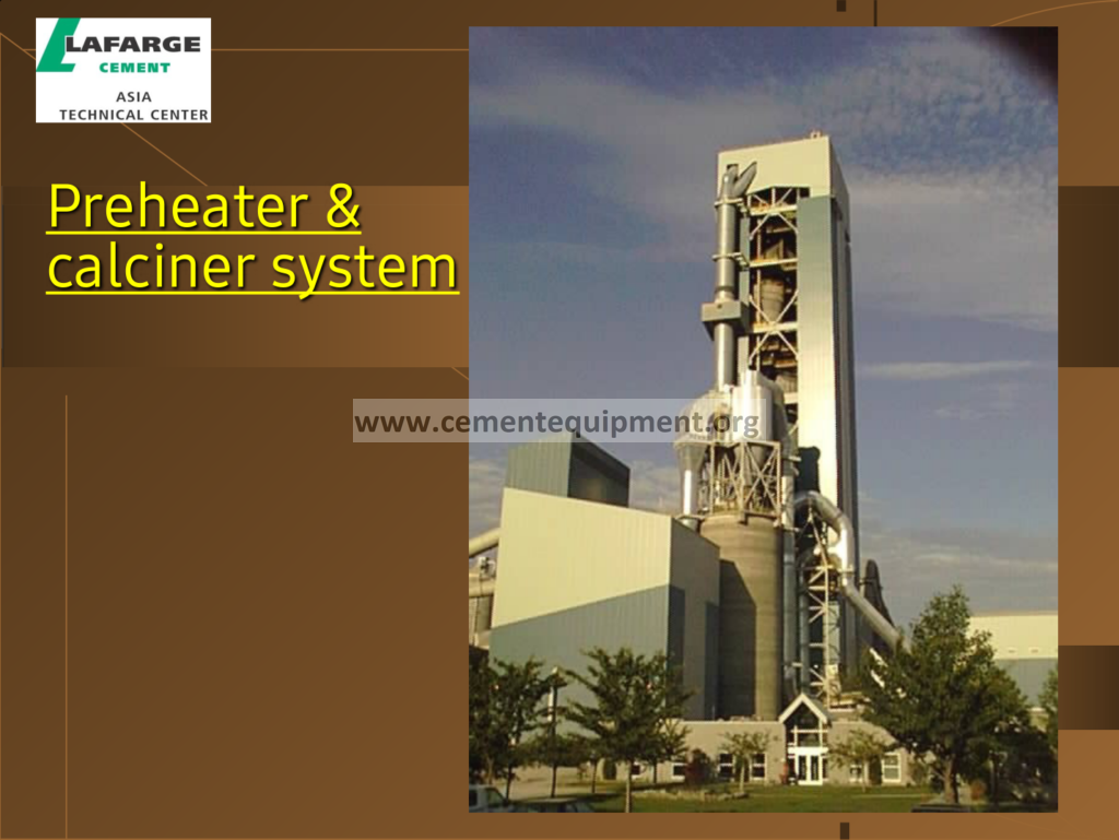
Preheater & Calciner: Complete Technical Guide
The design of the preheater and the calciner is the engineering of the vertical reactor: the tower above the kiln must exchange the heat, complete the calcination and deliver the hot meal to the kiln within the tightest possible envelope of the pressure loss, the height and the cost: every meter of the tower costs steel, every Pascal of the draft costs kilowatts, and every degree of the recovery saves the fuel: the designer walks the same lines as the operator, but with the calculators of the future in hand: the geometry of the cyclones, the velocities of the ducts, the residence time of the calciner and the path of the tertiary air are the decisions that the plant lives with for thirty years.
The Complete Cement Technical Package (931 files including the books, the courses, the Excel tools and the presentations: $249.99 one-time: instant download via the PayPal payment) includes the design chapters of the preheater and the calciner: the cyclone calculations, the pressure loss sheets, the duct sizing tables and the revamp studies: this article walks the reader through the design discipline: the cyclone geometry, the pressure profile, the calciner vessel, the air routing and the kiln interface: the engineer closes the page with the design map of the tower.
The design of the tower is the negotiation between the conflicting requirements: the high separation efficiency wants the small cyclones, the low pressure loss wants the big ones: the long residence time wants the large calciner, the low capital cost wants the small one: the hot tertiary air wants the insulated duct, the low radiation wants the short one: the design is the optimization of the trade-offs, and this page presents each trade as the engineer sees it: the numbers, the constraints and the solutions.
1. The Architecture of the Preheater-Calciner Design
The design of the tower begins with the architecture: the arrangement of the stages, the cyclones and the ducts that defines the gas path and the structural envelope:
- The layout options: the twin-tower arrangement with the two parallel gas paths for the very large lines, the single-tower arrangement for the medium lines and the tower with the in-line or the separate-line calciner: the layout splits the gas and the meal flows to balance the cyclones and the ducts;
- The stage arrangement: the cyclones of each stage arranged around the central riser duct: the gas from the stage below enters the riser, meets the meal, and the cyclone of the stage separates the mixture: the riser is the exchange duct and the cyclone is the separator: the pair forms the stage cell;
- The suspension exchange: the heat exchange of the stage happens in the riser duct at the velocity of 15 to 25 m/s: the meal is dispersed into the gas by the splashing and the turbulence: the riser must be long enough to complete the exchange before the cyclone: the riser length is the exchange length;
- The structural system: the tower is the steel structure of the columns and the platforms: the cyclones hang on the structure, the ducts run between the stages and the calciner vessel sits at its level: the thermal expansion of the 100-meter structure is managed with the expansion joints and the supports;
- The material selection: the steel of the cyclones and the ducts with the internal wear protection: the castables and the inserts line the zones of the abrasion: the temperature service of the stages decreases from the bottom to the top: the material grades follow the temperature map;
- The access and the maintenance: the inspection doors, the cleaning ports, the platforms and the cranes: the tower must be maintainable at the height of 100 meters: the design of the access is the design of the maintainability;
The architecture is the skeleton of the tower: the stages are the floors, the risers are the stairs of the gas and the cyclones are the landings: the designer arranges the skeleton to minimize the duct lengths, the pressure losses and the steel weight: the architecture of the tower is the first sketch of the whole design: the arrangement that is elegant on the drawing is the arrangement that serves the plant for the decades.
2. The Cyclone Design: The Geometry and the Separation Efficiency
The cyclone is the unit cell of the tower, and its design is the most repeated calculation of the discipline: the designer sizes the cyclone to separate the meal at the acceptable pressure cost:
- The separation mechanism: the tangential entry spins the gas-meal mixture: the centrifugal force of the swirl throws the particles outward, the gas turns at the vortex finder and escapes the top: the particle size, the gas velocity and the cyclone diameter decide the separation: the physics of the swirl, condensed into the geometry;
- The design ratios: the classical proportions of the cyclone: the body diameter D, the inlet width and height, the cone angle, the vortex finder diameter and the outlet height: the ratios of the modern cyclones are tuned by the manufacturers: the geometry is the fingerprint of the separation performance;
- The separation efficiency and the cut size: the cut size of the preheater cyclone of 5 to 15 micrometers at the stage efficiency of 90 to 97%: the efficiency rises with the smaller diameter and the higher inlet velocity: the cyclone that separates better costs more pressure: the trade of the design;
- The collection efficiency curve: the efficiency as the function of the particle size: the fine particles below the cut size escape the stage: the escaped dust is caught by the stage above: the cascade of the stages compensates the imperfection of each stage: the tower efficiency is the product of the stages;
- The pressure loss of the cyclone: the loss of 400 to 700 Pa per stage: the loss components are the inlet contraction, the swirl friction and the vortex dissipation: the loss follows the square of the velocity: the velocity is the master dial of both the efficiency and the draft;
- The body diameter and the number of the cyclones: the large towers use the multiple cyclones per stage in parallel: the gas flow is split between the bodies: the parallel cyclones keep the individual diameters small and the efficiency high: the number of the cyclones follows the gas volume;
The cyclone design is the art of the swirl: the designer trades the efficiency against the pressure at every point of the tower: the small cyclone separates the meal but chokes the draft; the large one breathes easily but loses the fines: the modern design settles at the velocities of 15 to 22 m/s in the inlet and the cut sizes in the single digits of the micrometers: the cyclone that is right for the stage is the cyclone that serves the whole column: the unit cell of the tower, engineered to the millimeter.
3. The Pressure Loss of the Tower: The Fan and the Sizing
The pressure loss of the tower is the energy bill of the vertical reactor: the fan that draws the gas through the whole burning system is sized on the pressure profile of the design:
- The loss inventory: the cyclone losses (400 to 700 Pa per stage), the riser duct losses, the calciner vessel loss, the kiln and the hood losses: the total of the tower and the system of 3000 to 5000 Pa, up to 6000 Pa for the six-stage towers with the small cyclones;
- The fan selection: the induced draft fan of the line, sized for the maximum gas volume at the highest pressure: the fan power follows the flow and the pressure: the fan motor of the modern line draws 1500 to 3000 kW: the fan is the largest single consumer of the tower’s electricity;
- The velocity optimization: the duct velocities of 15 to 25 m/s balance the exchange, the separation and the losses: the velocity increase improves the exchange and the separation but costs the pressure: the optimum velocity is the economic minimum of the combined cost of the power and the equipment;
- The false air accounting: the design allows the false air of the seals and the doors: the false air dilutes the gas, cools the recovery and adds the fan load: the design target keeps the false air below 3 to 5% of the system gas: the seals are designed, not hoped;
- The dust loading: the gas carries the meal of the suspension: the dust loading of 300 to 800 g per cubic meter in the risers adds the exchange surface and the pressure losses: the design accounts for the loading in the cyclone and the duct sizing;
- The fan control margin: the design reserves the margin of the 10 to 15% for the deposits, the wear and the future conditions: the margin is the insurance of the draft: the fan that is sized at the edge is the fan that chokes at the first deposit;
The pressure loss is the tax of the recovery: every degree of the heat recovered through the stages must be paid for with the Pascals of the draft: the design discipline is the accounting of the trade: the stage that saves the 20 kJ per kg of clinker at the cost of the 500 Pa and the kilowatt of the fan power: the economic equation of the tower is written in the pressure profile: the designer and the operator both read it: the design selects the loss, the operation pays it.
4. The Risers, the Ducts and the Dispersion of the Meal
The ducts between the stages are the exchange chambers of the tower, and the dispersion of the meal in the gas is the hidden art of their design:
- The riser duct: the vertical duct that carries the gas from the stage below and receives the meal from the stage above: the gas velocity of 15 to 25 m/s suspends the meal: the riser length of 10 to 30 meters provides the residence time of 1 to 3 seconds for the exchange: the riser is the exchange reactor of the stage;
- The meal dispersion: the meal is introduced into the gas at the riser bottom or through the splash plates: the dispersion box breaks the agglomerated meal into the individual particles: the quality of the dispersion decides the surface area of the exchange: the poor dispersion is the hidden inefficiency of the stage;
- The splash plates and the deflectors: the mechanical elements that distribute the meal across the duct cross-section: the plates and the cones spread the meal into the gas stream: the deflectors also serve the erosion protection of the duct walls: the dispersion hardware is the tongue of the stage;
- The horizontal ducts: the connecting ducts between the cyclones and the tower sections: the horizontal runs must keep the velocity above the saltation (the settling) limit: the meal that settles in the horizontal duct is the deposit in the making: the velocity discipline of the ducts is the anti-deposit design;
- The gas distribution: the uniform flow across the riser cross-section: the swirl and the asymmetric entries distort the distribution: the design of the inlets and the splitters balances the gas across the parallel cyclones: the balanced flow is the balanced separation;
- The erosion and the wear: the meal-laden gas at the high velocity erodes the duct walls: the wear plates, the castable linings and the direction changes are armored: the duct design is the compromise of the velocity, the exchange and the erosion life;
The riser is where the tower does its work: the exchange of the heat happens in the seconds of the suspension, and the design of the riser decides how completely the seconds are used: the dispersion of the meal, the velocity of the gas and the length of the exchange are the three variables of the stage: the designer tunes them so that the meal reaches the gas temperature within the riser, and the cyclone then does the clean separation: the duct design is the exchange design, and the exchange design is the soul of the tower.
5. The Calciner Vessel: The Residence Time and the Burnout
The calciner is the reactor of the tower, and its design is dominated by the residence time of the particles and the burnout of the fuel:
- The vessel types: the vertical cylindrical vessel with the bottom cone and the tangential entries: the gas-meal mixture swirls upward through the vessel: the design variations (the inline, the separate-line, the down-draft) change the gas path and the residence profile;
- The residence time of the gas: the gas passes through the vessel in 2 to 5 seconds: the residence sets the time available for the fuel burnout and the calcination: the large vessels with the internal swirl extend the effective residence: the residence time is the first dial of the vessel design;
- The particle residence: the meal particles travel with the gas: the coarse particles and the fuel chars may fall back and recycle: the internal design (the cones, the swirl vanes) redistributes the particles: the particle residence is the honesty of the vessel about the fine and the coarse;
- The fuel burnout: the coal and the alternative fuels must burn out within the vessel: the burnout of the char is the function of the temperature, the oxygen and the residence: the design for the slow fuels (the petcoke, the refused-derived fuel) extends the residence and stages the combustion: the fuel is the client of the vessel design;
- The calcination kinetics: the carbonate decomposition at 850 to 900°C: the calcination rate of the fine meal is high, and the 85 to 95% degree is reached within the vessel residence: the design margin for the slower particles and the cooler spots is built into the sizing;
- The temperature and the oxygen distribution: the uniform temperature and the oxygen across the vessel: the fuel injection points and the tertiary air entries are arranged for the mixing: the dead zones of the vessel are the deposits in the making: the mixing design is the quality of the reactor;
The calciner vessel is the crucible of the suspension: the gas swirls, the fuel burns, the carbonate decomposes and the calcined meal leaves to the lowest cyclone: the design of the vessel is the design of the time: the seconds of the residence are the budget within which the combustion and the calcination must complete: the designer spends the seconds wisely: the vessel that gives the fuel its time is the vessel that burns the slow fuels, and the vessel that burns the slow fuels is the vessel of the alternative fuel strategy: the residence is the currency of the calciner.
6. The Tertiary Air Duct: The Route of the Recovered Heat
The tertiary air is the oxygen supply of the calciner, drawn from the cooler at 750 to 900°C: its duct is one of the largest and the most carefully insulated pipes of the plant:
- The purpose of the tertiary air: the calciner combustion needs the oxygen without the dilution of the kiln gas: the tertiary air is taken from the cooler (where the clinker heat is recovered) and routed up the tower: the tertiary air carries the heat AND the oxygen: the double gift of the cooler;
- The take-off point: the tertiary air is drawn from the cooler at the point where the air is the hottest and the dust loading is manageable: the take-off from the first or the middle section of the grate: the take-off position balances the temperature against the clinker dust carried;
- The duct sizing: the tertiary air duct of 2 to 4 meters in diameter for the large lines, at the velocity of 10 to 20 m/s: the duct is sized for the minimum pressure drop: the pressure drop of the tertiary air duct is paid by the cooler fans: the duct is the freeway of the air;
- The insulation and the radiation: the duct is insulated to hold the air temperature: the surface loss of the long duct cools the tertiary air and the calciner: the insulation of the tertiary air duct is the jacket of the recovered heat: the poorly insulated duct is the radiator of the tower;
- The expansion and the supports: the long duct expands with the temperature: the expansion joints and the spring supports accommodate the movements: the duct is anchored at the cooler and free at the tower: the thermal growth is the civil discipline of the pipe;
- The damper: the control damper of the tertiary air flow: the damper balances the air between the kiln and the calciner: the air split is the master balance of the burning system: the damper position is one of the most important set points of the plant;
The tertiary air duct is the middle way of the process: the air leaves the cooler, climbs the tower and enters the calciner, carrying the heat that the clinker gave it: the design of the duct protects the gift: the insulation keeps the heat, the sizing keeps the draft and the damper keeps the balance: the tertiary air duct is the artery of the burning system: the design of the artery is the design of the circulation: the plant that insulates, sizes and balances its tertiary air is the plant that burns the least fuel.
7. The Kiln Interface: The Hood, the Inlet and the Meal Delivery
The lowest part of the tower meets the kiln, and the interface between the two machines is the zone of the highest temperatures and the most demanding details:
- The kiln feed (the hot meal) delivery: the calcined meal from the lowest cyclone falls through the meal pipe into the kiln inlet: the meal at 820 to 880°C must be delivered evenly and without the gas short-circuits: the feed pipe and the flap valve protect the separation of the last stage;
- The kiln inlet housing: the stationary housing that connects the rotating kiln to the tower: the inlet seal closes the gap: the hot gas from the kiln enters the tower through the inlet: the housing is lined with the refractory and armored against the meal abrasion;
- The kiln riser duct: the vertical duct above the inlet that carries the kiln gas up to the calciner or the lowest cyclone: the riser receives the calciner fuel, the tertiary air and the meal in the inline designs: the riser is the mixing chamber of the bottom of the tower;
- The meal spread and the stability: the feed must be distributed across the kiln cross-section at the inlet: the spreader and the feed chute design prevent the meal pile at one side: the uneven feed is the root of the ring formations at the inlet: the delivery is the first impression of the meal in the kiln;
- The throat and the inlet rings: the internal restriction at the kiln inlet that shapes the gas flow and the meal retention: the throat design affects the material hold-up and the gas velocity: the throat is the last design element of the tower and the first of the kiln;
- The thermal protection: the inlet zone is the hottest of the tower: the castable and the brick protection of the housing, the riser and the throat: the water-cooled sections in the severe designs: the thermal protection is the armor of the interface;
The kiln interface is the handshake of the tower and the kiln: the hot meal falls into the rotating cylinder, the kiln gas rises into the tower and the two machines exchange the material, the heat and the disturbances: the design of the interface decides the smoothness of the handshake: the even meal, the sealed inlet and the armored riser keep the boundary calm: the interface that is designed well is invisible in the operation: the interface that is neglected shows in the rings, the seals and the stops: the handshake of the burning system, engineered to be silent.
8. The Bypass System: The Escape Valve of the Volatiles
The bypass is the branch that vents a portion of the kiln gas around the tower: the bypass protects the process from the volatile cycles by bleeding the gas that carries the alkalis, the sulfur and the chlorides:
- The purpose of the bypass: the kiln gas at the inlet carries the evaporated alkalis, the sulfates and the chlorides: without the escape, the volatiles condense in the tower and build the deposits: the bypass diverts 2 to 10% (up to 30% for the high-alkali raw materials) of the gas and removes the volatiles with it;
- The take-off: the branch duct at the kiln inlet or the riser: the take-off point is chosen where the volatile concentration is the highest: the bypass gas is quenched with the air or the water spray to condense the salts before the dedusting;
- The gas conditioning: the bypass gas at 800 to 1000°C is cooled in the conditioning tower or the mixing chamber: the cooling condenses the sulfates and the chlorides into the dust: the cooled gas passes the bag filter: the collected dust is the potassium and the sulfate concentrate, removed from the cycle;
- The dust disposal: the bypass dust is the by-product of the volatile control: the dust can be used in the fertilizers or the special applications, or landfilled: the bypass dust is the price of the clean cycle: the disposal is the last step of the bypass design;
- The energy and the output cost: the bypass removes the gas that carries the heat and the dust: the fuel consumption rises by the bypass share, and the output may fall: the bypass is the insurance that costs: the design minimizes the bypass to the minimum required by the chemistry;
- The decision to install: the raw materials with the high chlorides, the alkalis or the sulfur demand the bypass: the clinker of the waste-fired plants often needs the bypass for the chlorine control: the bypass is the design answer to the chemistry of the region;
The bypass is the safety valve of the volatile economy: the alkalis and the chlorides must leave the system, and the bypass is the controlled exit: the design of the bypass is the design of the escape: the take-off at the right point, the quench at the right rate and the dust at the right place: the plants that need the bypass and do not have it fight the deposits and the kiln stops; the plants that have it use it as the deliberate instrument of the chemistry control: the bypass is the escape valve of the tower, opened by the design and set by the operator.
9. The NOx and the CO Management in the Preheater-Calciner
The tower is the emission reactor of the burning system: the NOx of the process is formed and partly reduced within the preheater and the calciner, and the CO is the unburned fuel that must be completed:
- The thermal NOx formation: the nitrogen of the combustion air oxidizes at the high flame temperatures (above 1400°C): the kiln flame is the main source of the thermal NOx: the calciner at 850 to 900°C forms little thermal NOx of its own: the kiln is the NOx factory and the tower is the NOx cleaner;
- The staged combustion in the calciner: the fuel is injected in the stages with the reduced oxygen in the first stage: the fuel-rich zone reduces the NOx formed in the kiln gas: the NOx reduction of 30 to 60% within the calciner: the staged calciner is the first NOx control of the modern plant;
- The selective non-catalytic reduction (SNCR): the ammonia or the urea injection into the calciner at the 850 to 950°C window: the ammonia reacts with the NOx to the nitrogen and the water: the SNCR is the additive-based control of the tower: the temperature window of the injection is the precision of the method;
- The CO management: the carbon monoxide of the incomplete combustion: the CO at the tower exit above the limit is the fuel loss and the emission alarm: the CO control is the oxygen discipline of the calciner and the kiln: the CO spike follows the fuel surge or the air starvation;
- The oxygen profile: the oxygen at the kiln inlet of 1 to 3% and at the tower exit of 1 to 3%: the profile between the two points tells the combustion story of the whole column: the oxygen control is the common thread of the NOx, the CO and the deposits;
- The emissions of the alternative fuels: the waste-derived fuels bring the organic emissions and the chlorine: the CO and the total organic carbon (TOC) are watched continuously: the emission design of the tower includes the monitoring and the control capability;
The tower is where the emissions of the burning system are made and unmade: the NOx of the kiln flame is reduced in the staged calciner, the SNCR finishes the job at the temperature window, and the CO is the leak of the incomplete combustion that the oxygen discipline stops: the emission design of the tower is the design of the chemistry of the nitrogen and the carbon: the plant that combines the staged combustion, the SNCR and the oxygen control meets the limits with the margin: the tower as the emission reactor, designed and operated as one.
10. The Design for the Buildup Prevention: The Coatings and the Cannons
The deposits are the chronic disease of the tower, and the good design is the preventive medicine: the anti-buildup design is built into the geometry, the materials and the cleaning systems:
- The velocity and the angle discipline: the horizontal duct runs at the velocities above the saltation limit, the cones at the angles above the repose of the deposits (55 to 65 degrees): the meal that slides cannot stick, and the meal that settles becomes the deposit: the geometry is the first defense;
- The smooth surfaces: the welds ground, the flanges aligned and the internal ledges eliminated: the deposit needs the foothold: the smooth surface denies it: the attention to the internal details is the invisible quality of the design;
- The insulating and the double walls: the cold walls condense the volatiles: the insulation of the duct walls keeps the inner surface above the condensation temperature: the double-wall cyclones and the insulated ducts keep the salts in the gas: the insulation is the anti-condensation design;
- The air cannons: the shock-blast cleaning devices mounted on the cones, the risers and the calciner: the cannons fire the compressed air pulses that shatter the deposits: the cannon layout is the firefighting grid of the tower: the placement of the cannons is a design discipline of its own;
- The cleaning doors and the access: the doors at the deposit-prone points allow the manual rodding and the visual inspection: the access design balances the cleaning need against the false air: the doors that are opened rarely are the doors that leak little;
- The material selection for the deposit zones: the wear-resistant and the low-adhesion linings at the sticky zones: the special castables and the inserts resist the sulfate attack: the materials are the armor of the surfaces that the deposits love;
The anti-buildup design is the war of the surfaces: the deposit needs the cold wall, the foothold and the quiet zone: the design denies all three: the insulated walls stay above the condensation, the smooth cones deny the foothold and the cannons attack the growth: the tower that is designed against the deposits is the tower that runs the year between the cleanings: the design for the cleanliness is the design for the availability: the cannons and the cones, the insulation and the angles: the tower’s immune system, engineered in.
11. The Revamp and the Upgrading of the Existing Towers
Most of the towers operating today were designed decades ago, and the revamp of the preheater and the calciner is the classic route of the plant upgrading: the revamp is the design discipline applied to the existing steel:
- The capacity revamp: the increase of the line output by the modification of the tower: the larger cyclones, the added stage, the larger calciner or the calciner addition: the capacity revamp of the preheater kiln (the precalciner installation) is the historical transformation that doubled the outputs of the old lines;
- The efficiency revamp: the reduction of the heat consumption: the added stage (from four to five), the improved cyclones, the better insulation: the efficiency revamp pays the fuel savings: the added stage is the classic efficiency project of the tower;
- The revamp constraints: the existing steel, the foundations and the fan set the boundaries: the revamp is the puzzle of the fit: the new cyclones must fit the old structure, the new fan must fit the old housing: the revamp design is the design within the envelope;
- The fan and the pressure budget: the revamp rarely adds the pressure: the old fan sets the budget: the improved cyclones that separate better at the same pressure are the engineering target: the pressure budget is the master constraint of the revamp;
- The phased implementation: the revamp in the annual shutdowns: the stages upgraded one by one, the calciner added in the planned stop: the phasing spreads the capital and the risk: the phased revamp is the gradual transformation of the tower;
- The post-revamp validation: the performance tests after the revamp: the temperatures, the pressures and the consumption vs the design: the validation closes the project with the evidence: the revamp that is not measured is the revamp that is not believed;
The revamp is the second life of the tower: the steel that was erected for the four stages accepts the fifth, the kiln that was fed the simple preheater accepts the calciner, and the line that produced the 3000 tons produces the 5000: the revamp is the art of the transformation within the constraints: the old steel, the old fan and the old foundations are the puzzle, and the new capacity, the new efficiency and the new fuel flexibility are the solution: the tower is not the museum piece, it is the living machine that the design re-invents: the revamp discipline is the design discipline of the second decade.
12. The Key Performance Indicators of the Preheater-Calciner: The Table of the Design
The design and the operation of the tower are judged by the set of the numbers: the table below collects the typical windows of the preheater-calciner of the modern dry-process line:
| Parameter | Typical window | Design and operating role |
|---|---|---|
| Number of the stages | 4 – 6 | Heat recovery vs pressure loss trade |
| Top stage gas temperature | 280 – 380 °C | Recovery quality, mill drying power |
| Kiln feed temperature | 820 – 880 °C | Preheating and calcination result |
| Calcination degree at kiln inlet | 85 – 95% | Calciner performance, kiln load |
| Cyclone inlet velocity | 15 – 25 m/s | Separation efficiency vs pressure |
| Stage separation efficiency | 90 – 97% | Dust circulation, stage health |
| Total tower pressure loss | 3000 – 5000 Pa | Fan sizing, energy cost |
| Oxygen at tower exit | 1 – 3% | Combustion completeness, NOx |
| Calciner residence time | 2 – 5 s (gas) | Fuel burnout, calcination degree |
| Tertiary air temperature | 750 – 900 °C | Calciner heat input, recovery |
The table is the scoreboard of the tower: the designer sizes to the windows and the operator operates within them: the numbers are the shared language of the design office and the control room: the stage temperatures speak of the exchange, the pressures of the deposits and the calcination degree of the reactor: the plant that trends the full table knows its tower: the KPI discipline is the measurement of the vertical reactor: the tower is tall, and the numbers of its health are the ten lines of the table.
13. The Frequently Asked Questions
What is the difference between a preheater and a calciner in the design?
The preheater is the cascade of the cyclones and the risers that exchanges the heat between the kiln gas and the meal: the calciner is the combustion vessel where the fuel burns and the calcination completes: in the design, the preheater is sized on the heat exchange and the separation, and the calciner on the residence time and the burnout: the two are the different reactors of the same tower.
Why are the cyclones of one stage often multiple?
Because the separation efficiency improves with the smaller cyclone diameter, and the large gas volumes of the big lines must be split: the parallel cyclones per stage keep the individual diameters small and the efficiencies high: the gas is distributed between the bodies and the meal is collected from all of them.
How much pressure loss does one cyclone stage cost?
Typically 400 to 700 Pa per stage, with the total tower loss of 3000 to 5000 Pa for the five-stage systems: the loss is the price of the separation and the exchange: the fan that overcomes it draws the kilowatts of the plant: the designer trades the loss against the recovery and the efficiency.
What limits the residence time in the calciner?
The gas velocity and the vessel volume: the residence time of the gas is the vessel volume divided by the gas flow, typically 2 to 5 seconds: the residence is extended by the larger vessels and the internal designs, and shortened by the velocity: the slow-burning alternative fuels demand the longer residence: the residence is the currency of the fuel flexibility.
When is the bypass needed?
When the volatile cycles (the alkalis, the sulfur, especially the chlorides) exceed the tolerance of the tower: the raw materials and the alternative fuels with the high chloride demand the bypass of 2 to 10% or more: the bypass removes the volatile-rich gas and protects the tower from the deposits: the need is decided by the chemistry of the region and the fuel policy.
What is the simplest way to improve the efficiency of an old tower?
The insulation and the seal repairs first, then the cyclone internals and finally the added stage: the small measures (the sealed doors, the insulated walls, the rebalanced air) often recover the lost degrees at a fraction of the capital: the audit of the pressure and the temperature profile finds the cheapest savings: the efficiency revamp starts with the data, not with the steel.
14. Conclusion
The design of the preheater and the calciner: the engineering of the vertical reactor: the cyclone geometry and the separation, the pressure profile and the fan, the risers and the dispersion, the calciner residence and the burnout, the tertiary air, the kiln interface, the bypass and the emission controls: the tower is the negotiation of the conflicts, resolved in the millimeters of the geometry and the Pascals of the draft: the design is the discipline of the trade-offs, and the revamp is the discipline of the transformation: the engineer who designs the tower designs the energy of the plant for the next thirty years.
The Complete Cement Technical Package includes the preheater and the calciner design chapters with the cyclone calculations, the pressure loss sheets, the duct sizing tables and the revamp studies: the one-time price of $249.99: the instant download: the library of the tower design: the engineer of the package sizes the cyclones, checks the pressure budget and plans the revamps: the vertical reactor of the plant, from the top cyclone to the kiln inlet, mastered with the full documentation.
Get this preheater and calciner design guide + the full 931-file package
$249.99 — one-time purchase, instant download, lifetime access
This file is part of the Complete Cement Technical Package (931 files) available from cementequipment.org. Respective rights holders; library copy for the licensed single user.