Kiln Burning System: Complete Technical Guide
The kiln burning system is the thermodynamic engine of the cement plant: the place where the fuel, the air and the raw meal meet in the flame and the reactions of the clinker formation run to completion: the burning system includes the burner and its flame, the combustion of the solid, the liquid and the gaseous fuels, the heat transfer from the flame to the bed, the reactions of the burning zone and the gas atmosphere that carries the heat to the preheater: it is the most studied and the most optimized process of the cement industry, because its efficiency decides the heat consumption of the entire plant and its stability decides the quality of every tonne of clinker.
The Complete Cement Technical Package (931 files including the books, the courses, the Excel tools and the presentations: $249.99 one-time: instant download via the PayPal payment) includes this kiln burning system guide with the combustion diagrams, the flame geometry sheets, the reaction tables and the emission control chapters: the logarithm of the knowledge for the process engineers, the kiln operators and the combustion specialists: this article walks the file: the combustion chemistry, the flame, the heat transfer, the burning zone reactions, the air system, the fuels, the emissions and the stability of the process: the reader leaves with the complete thermal logic of the kiln burning in hand.
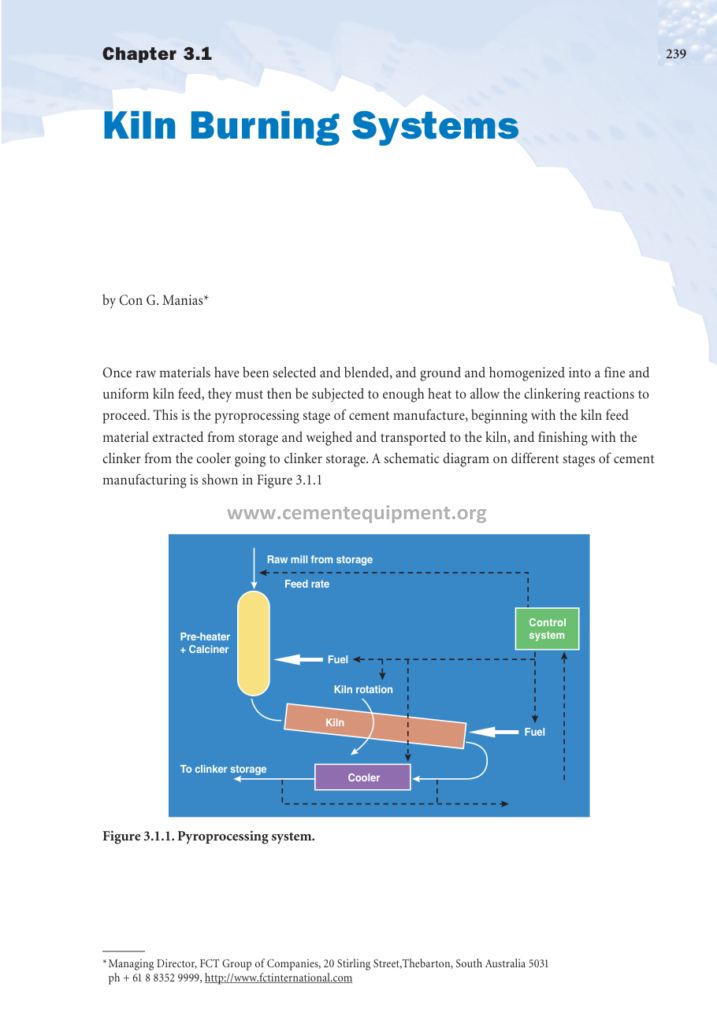
The burning system is best understood as a chain of five processes: the fuel preparation delivers the combustible, the burner forms the flame, the flame radiates the heat, the bed absorbs it and reacts, and the gas carries the surplus away through the preheater: each process is tied to the next, and the operator controls the whole chain through the five instruments: the fuel rate, the air rate, the draft, the feed rate and the burner settings: this page follows the chain in the same order as the file of the package.
1. The Combustion Chemistry of the Kiln: The Oxidation of the Fuel
The burning of the fuel is the oxidation of the carbon and the hydrogen into the heat release of the flame: the stoichiometry of the combustion is the grammar of the burning system:
- The combustion equations: the carbon burns to CO2 releasing about 32.8 MJ per kg of carbon, the hydrogen to water vapor releasing about 120 MJ per kg of hydrogen, the sulfur to SO2: the complete oxidation releases the full calorific value, the partial oxidation to CO releases only about 9.9 MJ per kg of carbon: the complete combustion is the economy of the flame;
- The stoichiometric air: the air requirement of the combustion follows the fuel composition: the coal with 60 to 80% carbon and 3 to 6% hydrogen needs about 7 to 10 kg of air per kg of coal, the natural gas about 15 to 17 kg of air per kg of gas: the theoretical air of the fuel is the baseline of the excess air control;
- The excess air: the real combustion runs with 1.5 to 3% oxygen in the kiln exit gas, that is 105 to 115% of the theoretical air: the excess air guarantees the complete burn-out but wastes the heat to the stack: the oxygen target is the compromise between the burn-out and the loss;
- The CO and the reducing atmosphere: when the oxygen falls below the stoichiometric need, the combustion leaves the CO in the gas: the reducing atmosphere damages the clinker phases, the coating and the refractory: the CO alarms at 0.3 to 0.5% trigger the immediate response of the operator;
- The combustion temperature: the adiabatic flame temperature of the fuel-air mixture reaches 1800 to 2200 °C before the dilution and the heat losses: the actual flame temperature of 1700 to 2000 °C depends on the air preheat from the cooler: the hotter the secondary air, the hotter the flame;
The chemistry sets the operating targets of the whole system: the fuel analysis of every delivery, the oxygen of the kiln exit gas and the CO of the same measurement: the combustion control is the continuous management of the stoichiometry: the analyzer at the kiln exit is the balance sheet of the burning, read every minute of every shift.
2. The Flame of the Kiln: The Anatomy of the Burning Jet
The flame is the visible form of the combustion, and its geometry controls the heat distribution of the burning zone: the kiln flame anatomy is studied in every serious burning system:
- The flame structure: the flame of the kiln divides into the internal recirculation zone at the nozzle, the combustion zone where the volatiles burn, and the tail zone where the char finishes: the core of the flame at 1700 to 2000 °C, the outer shell cooler against the clinker bed and the lining;
- The flame length: the burning zone of the kiln needs the flame of 8 to 15 times the burner diameter: the too-long flame pushes the heat to the feed end and leaves the clinker under-burnt, the too-short flame overheats the nose section and the refractory: the flame length follows the momentum and the fuel volatility;
- The flame stability: the stable flame anchors at the nozzle by the recirculation of the hot combustion products: the ignition point, the flicker and the color of the flame are the visible health signs: the stable flame means the stable heat input to the bed;
- The radiation of the flame: the luminous flame of the coal and the oil radiates strongly because of the soot and the char particles at the high temperature: the gas flame radiates less and transfers more by the convection: the radiation is the dominant heat transfer of the burning zone;
- The flame temperature profile: the temperature along the flame rises to the peak at 20 to 40% of the length and falls towards the tail: the peak position over the bed is the design goal of the burner adjustment: the peak aligned with the sintering reaction zone;
The flame is controlled, not just observed: the burner adjustments, the air distribution and the fuel quality shape it, and the cameras and the pyrometers read it: the flame of the stable kiln sits at the same position, in the same color band and the same length, shift after shift: the deviation of the flame is the first warning of the burning problems.
3. The Heat Transfer of the Burning Zone: From the Flame to the Clinker
The burning zone transfers the heat of the flame to the clinker bed through the three classical mechanisms, and each has its engineering figures:
| Transfer path | Mechanism | Typical share in the burning zone |
|---|---|---|
| Flame radiation to the bed | Luminous flame radiation, gas radiation | 40 – 60% |
| Refractory radiation | Hot lining radiates the dark phase of the bed | 20 – 30% |
| Gas convection to the bed | Hot gas velocity along the bed surface | 10 – 20% |
The heat transfer logic of the burning zone:
- The radiation from the flame: the flame radiates to the exposed bed and the lining: the radiation depends on the fourth power of the temperature: the flame at 1800 °C radiates almost twice the energy of the flame at 1500 °C: the flame temperature is the first lever of the heat input;
- The radiation from the lining: the hot coating and the brick radiate the heat stored in them to the bed when the bed surface passes: the lining is the flywheel of the heat transfer: the stable lining temperature smooths the heat input between the rotations;
- The convection: the gas velocity along the bed surface carries the heat by the convection: the effect is secondary in the burning zone but dominates in the preheater and the cooler: the convection becomes important when the flame is long and the gas leaves the bed quickly;
- The heat absorption of the bed: the clinker bed absorbs the heat by the radiation of its exposed surface and by the conduction inside the tumbling bed: the bed depth, the rotation and the filling degree control the renewal of the exposed surface: the deeper bed hides the material from the radiation;
The heat transfer decides the temperature distribution along the kiln: the burning zone at 1400 to 1500 °C in the material, the gas at the flame temperature: the heat balance of the burning zone closes the books of the kiln: the specific heat consumption of the modern line, 2900 to 3400 kJ per kg of clinker, is the sum of all the transfer efficiencies of the system.
4. The Reactions of the Burning Zone: The Birth of the Clinker Phases
The burning zone is the reaction vessel of the clinker: the calcined meal, already 90 to 95% decarbonated by the precalciner, completes the formation of the cement compounds:
- The liquid phase formation: at about 1338 °C the mixture of the calcium oxide, the silica, the alumina and the iron oxide begins to melt partially: the liquid phase of 24 to 30% of the mass forms the transport medium of the reactions: the liquid is the crucible of the clinker;
- The alite formation: the tricalcium silicate C3S forms in the liquid from the dicalcium silicate C2S and the calcium oxide: the reaction is slow and needs the temperature, the time and the liquid: the alite content of 55 to 70% of the clinker is the strength engine of the cement;
- The belite formation: the dicalcium silicate C2S forms earlier from the calcium oxide and the silica at 900 to 1200 °C in the solid state: the belite is the survivor of the under-burned kiln and the second strength phase of the clinker;
- The interstitial phases: the tricalcium aluminate C3A and the tetracalcium aluminoferrite C4AF crystallize from the liquid during the cooling: their amounts follow the alumina and the iron of the raw mix: the C3A from the liquid and the cooling rate;
- The free lime: the calcium oxide that did not reach the alite remains as the free lime: the free lime above 1.5 to 2.0% marks the under-burning and endangers the cement soundness: the free lime of the clinker is the quality scoreboard of the burning zone;
The reaction kinetics of the burning zone set the operating windows: the clinker must hold 10 to 20 minutes at 1400 to 1500 °C with the stable liquid phase to complete the alite formation: the burning zone temperature, the retention time and the liquid amount are the three dials of the clinker quality: the process engineer reads the free lime and the microscopical structure of the clinker as the verdict of the burning.
5. The Air System of the Burning: The Secondary and the Tertiary Streams
The burning system breathes through the cooler: the combustion air arrives preheated, and the three air streams of the kiln balance the combustion:
- The secondary air: the hot air drawn from the cooler through the kiln hood around the burner: the secondary air at 700 to 1100 °C provides 15 to 30% of the combustion oxygen: the hood pressure, slightly negative, controls the suction: the hotter the secondary air, the hotter and the more economical the flame;
- The tertiary air: the branch duct from the cooler to the calciner carries 25 to 45% of the combustion air: the tertiary air at 750 to 950 °C burns the calciner fuel: the damper of the duct balances the kiln and the calciner flows;
- The primary air: the burner’s own air at 6 to 12%: the momentum of the flame: the smallest stream with the largest influence on the flame shape;
- The cooler excess air: the air not consumed by the kiln and the calciner leaves the cooler at 200 to 350 °C to the dust filter or to the mills: the excess air share of 10 to 25% pays for the cooling of the clinker and feeds the drying of the plant;
- The fan and the draft: the ID fan at the preheater top pulls the whole system: the pressure profile from the hood (near zero) to the tower top (minus 4500 to 6500 Pa) keeps the gas flowing and the seals tight: the false air into the system cools the gas and costs the efficiency;
The air system is the circulation of the burning: the cooler heats the air, the hood distributes it, the kiln and the calciner consume it, and the fan evacuates it: the balance of the streams is measured by the oxygen readings at the kiln exit and the calciner exit: the air balance sheet of the line is the most instructive page of the process data.
6. The Fuels of the Burning System: The Portfolio of the Kiln
The burning system is fuel-agnostic in the modern plants: the kiln burns whatever the market and the permits allow, and the fuel portfolio shapes the combustion control:
- The coal: the standard fuel with the calorific value of 25 to 32 MJ per kg, the volatile matter of 20 to 40% and the ash of 5 to 20%: the kiln burns the coal ground to 2 to 5% residue on 90 micron: the coal ash enters the kiln feed and changes the clinker composition: the ash correction of the raw mix is the classical coal discipline;
- The petcoke: the high calorific petroleum coke of 32 to 36 MJ per kg with the low volatile content of 8 to 12% and the high sulfur of 3 to 7%: the petcoke needs the finer grinding, the higher momentum and the higher excess air: the sulfur of the petcoke feeds the sulfur cycle of the pyroprocess;
- The natural gas: the cleanest fuel with the calorific value of 38 to 42 MJ per cubic meter (34 to 38 MJ per kg as the mass basis): the gas flame is short and the radiation lower: the burner momentum for the gas requires the higher air contribution: the gas burns without the ash and the sulfur: the fuel of the emission-sensitive plants;
- The fuel oil: the heavy fuel oil of 38 to 42 MJ per kg with the sulfur up to 3%: the atomized spray flame radiates strongly: the oil heating, the filtration and the atomization are the equipment requirements: the oil stock and the heating systems keep the fuel ready;
- The alternative fuels: the solid recovered fuels, the tires, the plastics, the solvents and the sludges: the calorific values of 10 to 30 MJ per kg with the high moisture and the chlorine contents: the feed limits of the alternative fuels are set by the process stability and the emission permits: the co-processing keeps the kiln as the thermal recycler of the region;
The fuel quality enters the burning calculations through the three parameters: the calorific value, the volatile content and the ash and the sulfur: the fuel changes are staged in the operation: the fuel portfolio of the burning system is the economic strategy of the plant, and its control is the daily arithmetic of the control room.
7. The Emissions of the Burning: The Product of the Combustion
The burning system is the emission source of the cement plant, and its gas cleanup is part of the system:
| Emission | Origin in the burning | Control measure |
|---|---|---|
| NOx | Thermal NOx of the flame, fuel NOx | Flame shaping, staged combustion, SNCR |
| SO2 | Sulfur of the fuel and the raw material | Raw mix sulfur control, desulfurization systems |
| CO and TOC | Incomplete combustion | Excess air control, burner tuning |
| Dust | Preheater gas, cooler exhaust | Bag filters, ESPs |
| HCl and organics | Chlorine and organics of the waste fuels | Kiln temperature discipline, activated carbon, scrubbing |
The emission control of the burning is a process control in itself: the NOx responds to the flame and the staging, the SO2 to the sulfur input, the organics to the combustion temperature: the emission monitoring reports of the plant are the legal scoreboard of the burning system: the process engineer holds the permit limits as the hard constraints of every operating decision.
8. The Burning Zone Indicators: The Operating Dial of the System
The state of the burning system is read from the classical indicator set, and the skilled operator reads the whole burning zone from the pattern of the instruments:
- The burning zone temperature: measured by the pyrometer (the ratio pyrometers) sighting the clinker surface or the flame base: the operating band 1350 to 1500 °C: the pyrometer reading is the primary quality indicator of the sintered clinker;
- The kiln drive current: the torque of the rotation reflects the charge, the viscosity of the liquid phase and the coating: the rising current with the falling temperature signals the washy material, the falling current with the hot clinker signals the over-burning: the drive current is the mechanical mirror of the burning zone;
- The kiln exit gas temperature and the O2: the gas leaving the burning zone at 950 to 1100 °C with the oxygen of 1.5 to 2.5%: the pair indicates the combustion quality and the heat input: the O2 below the band with the CO rising is the danger signal of the reducing atmosphere;
- The free lime of the clinker: the laboratory result of the hour: the free lime of 0.5 to 1.5% in the good clinker: the rising free lime marks the under-burning, the falling free lime with the rising current marks the over-burning: the free lime trends the quality of the burning zone with the delay of the sampling;
- The clinker appearance: the clinker samples, their color, their density and their granulation: the well-burned clinker is dense, dark and uniformly granulated, the under-burned is light and dusty: the experienced operator photographs the clinker samples through the shift and compares them with the archive;
The indicator set is redundant by design: the temperature, the current, the O2, the free lime and the clinker appearance must agree: when one indicator contradicts the others, the instrument or the sampling is suspect: the process engineer who demands the agreement of the five indicators prevents both the equipment errors and the operating mistakes.
9. The Stability of the Burning: The Philosophy of the Control
The burning system is managed by the philosophy of the stability: the system is a chain of the thermal flywheels, and the control of the chain follows the rules that the industry learned over the decades:
- The small and the constant changes: the fuel and the feed changes are made in the small steps at the fixed intervals: the large steps create the waves of the heating and the cooling that take hours to dampen: the operator moves the setpoints like the helm of the ship, slowly and steadily;
- The cascade of the control: the calciner temperature controls the calciner fuel, the kiln exit oxygen controls the kiln fuel, and the burning zone temperature and the free lime trim the master: the cascade structure matches the response times of the process: the fast loops stabilize the slow ones;
- The feed-following operation: the kiln feed and the fuel move in the coupled ratio with the protective envelopes: the feed swings are limited in the rate, the fuel follows with the temperature confirmation: the model-based controllers improve the coupling beyond the simple ratios;
- The disturbance anticipation: the raw mix changes, the fuel switches and the weather events are the known disturbances: the operator anticipates them from the silo levels, the mill status and the reports: the anticipation beats the response: the control room with the good anticipation runs the smooth line;
- The measured patience: the retention time of the kiln of 20 to 40 minutes means that the effect of every change appears after the delay: the operator who judges the result too early chases the ghosts and creates the waves: the measured patience of the pyro control is the professional virtue;
The stability of the burning is not the absence of the actions but the discipline of the actions: the records of the good campaigns show the flat fuel curves, the constant temperatures and the narrow free lime band: the stability culture, measured in the standard deviations of the process variables, is the highest KPI of the burning system.
10. The Burning System Troubleshooting: The Disturbances and the Responses
The burning system failures announce themselves in the indicator patterns, and the standard responses are drilled in the shift teams:
| Disturbance | Indicators | Standard response |
|---|---|---|
| The washy burning zone | Rising current, falling temperature, dusty clinker | Raise the flame temperature stepwise, reduce the feed, check the raw mix |
| The over-burnt clinker | Falling current, high temperature, dense clinker balls | Reduce the kiln fuel, adjust the feed, watch the ring formation |
| CO alarm | O2 falling, CO rising, flame darkening | Reduce the fuel immediately, increase the draft, find the oxygen source |
| The coating collapse | Burning zone temperature swings, shell hot spot, lumps | Stabilize the temperature, avoid the thermal overcorrection, monitor the shell scan |
| The fuel change interruption | Fuel flow alarms, temperature drift | Switch to the standby fuel or the insurance burner, hold the temperatures |
The troubleshooting table is the quick reference of the control room: the responses are the first steps, always followed by the diagnosis of the cause: the same indicator pattern can hide the raw mix change, the fuel quality drop or the burner nozzle erosion: the investigation, with the mill reports and the analyzer data, follows the standard response: the troubleshooting discipline of the file separates the symptom treatment from the cause treatment.
11. The Heat Balance of the Burning System: Where the Megajoules Go
The heat balance of the kiln burning system accounts for every megajoule of the fuel input, and its structure is the same in every plant:
- The useful heat: the clinker formation heat of about 1750 to 1950 kJ per kg of clinker: the share of 50 to 60% of the input: the theoretical minimum of the process, fixed by the chemistry of the decarbonation and the clinker formation;
- The exhaust gas losses: the preheater exit gas at 280 to 340 °C carries 12 to 18% of the input: the heat of the gas, the more efficient the tower: the heat recovery to the raw mill and the coal mill reclaims part;
- The cooler losses: the cooler exhaust air and the radiation of the cooler shell: 6 to 12%: the cooler efficiency, the clinker exit temperature and the air recovery decide the loss;
- The radiation and the convection of the shell: the kiln shell, the tower and the ducts radiate 5 to 10% of the input: the shell insulation and the coating of the kiln minimize the loss: the burning zone temperature and the shell area set the radiation;
- The dust and the material losses: the kiln dust and the spillage carry the sensible heat out: 1 to 3%: the good dedusting and the dust recycling keep the loss small: the heat balance closes with the chemical losses and the miscellaneous terms;
The heat balance is the scorecard of the burning: the plants run the balance test yearly and compare the losses against the benchmarks: each percentage point of the exhaust loss is worth real fuel money: the heat balance of the file, with the calculation sheets and the reference bands, is the audit instrument of the burning system efficiency.
12. The Advanced Burning Control: The Models and the Optimization
The burning system of the modern plants is increasingly controlled by the advanced systems that learn the behavior of the kiln:
- The predictive control: the model predictive controllers hold the process variables within the envelopes while optimizing the fuel consumption: the controller predicts the kiln response over the horizon and moves the setpoints smoothly: the MPC reduces the standard deviation of the burning zone temperature by 30 to 50% against the manual operation;
- The fuzzy logic controllers: the rule-based systems that imitate the best operator: the control actions condition the rules on the process states: the fuzzy controllers run the kiln through the normal and the transitional states: the mature systems of the industry since the 1990s;
- The expert system advisory: the systems that recommend the setpoints and the actions to the operator: the expert knowledge encoded from the campaigns: the operator remains the decision maker with the advisor at the side: the advisory mode preserves the operator’s ownership;
- The soft sensors: the models that estimate the unmeasured variables: the burning zone temperature from the shell scan and the drive current: the free lime from the process data: the soft sensors fill the gaps of the hard measurements and trim the control;
- The optimization economics: the controller minimizes the total cost: the fuel, the raw material and the penalty emissions of the NOx: the economic optimization of the burning runs inside the safety and the quality constraints: the plant ledger is the objective function;
The advanced control is a layer over the well-instrumented and the well-operated plant: the models need the stable instruments, the good data and the disciplined operators: the advanced control results are measured in the fuel savings of 1 to 5% and the quality variance reductions: the burning system of the future is the collaboration of the operators and the models, not the replacement of one by the other.
13. The Frequently Asked Questions
Why is the flame of the kiln so important for the clinker quality?
Because the flame is the heat source of the sintering: its temperature, its length and its position decide the temperature profile of the burning zone, the formation of the alite, the liquid phase and the coating: the flame that is too short leaves the nose overheated, the flame too long leaves the feed end hot and the clinker under-burned: the flame control is the clinker control.
What is the ideal oxygen content at the kiln exit?
The classical target is 1.5 to 2.5% oxygen: below it the combustion remains incomplete with the CO and the reducing atmosphere, above it the heat escapes and the NOx rises: the exact band depends on the fuel and the plant: the oxygen analyzer at the kiln exit is the most trusted instrument of the burning control.
How does the alternative fuel change the burning system?
The alternative fuels bring the lower calorific values, the higher moisture and the chlorine and the heavy metals: the flame is cooler and longer, the combustion must be confirmed by the temperatures and the emissions, and the feed limits per fuel protect the process: the burning system with the high substitution rates is tuned like a different kiln.
What is the reducing atmosphere and why is it dangerous?
The reducing atmosphere occurs when the oxygen is insufficient and the CO appears: it destabilizes the clinker phases, prevents the coating formation, attacks the refractory and raises the sulfur volatilization: the consequence is the kiln operation disaster over the hours: the CO alarm is the first emergency signal of the burning system.
Can the heat consumption of the burning be reduced below 2900 kJ per kg?
The well-designed and the well-operated modern lines achieve the 2900 to 3100 kJ per kg of clinker in the dry process; values below this are rare and require the excellent raw mix stability, the efficient tower and the recovery of the waste heat: the theoretical minimum of about 1750 kJ per kg of clinker formation leaves the losses that the engineering attacks one by one.
Does the package include the burning system tools?
The Complete Cement Technical Package includes the combustion guides, the heat balance calculators and the flame and the burner documents: the engineers use the stoichiometry sheets and the air balance tools of the package: the 931 files of the package, the tools included.
14. Conclusion
The kiln burning system: the chemistry of the combustion, the anatomy of the flame, the heat transfer to the bed, the reactions of the clinker phases, the air balance and the emissions: the thermodynamic engine that converts the fuel into the clinker: the operator who reads the flame, the O2 and the current holds the whole system in his hands: the engineer who closes the heat balance keeps its ledger: the burning system, understood and stabilized, delivers the cheapest and the best clinker of the plant.
The Complete Cement Technical Package includes the kiln burning system guide with the combustion diagrams, the flame geometry sheets, the reaction tables and the emission control chapters: the one-time 249.99: the instant download: the library of the cement: the burning file: the work of the professional: the cement knowledge, the measured: the flame of the package, the fire of the plant: the career of the engineer, burned right.
Get this kiln burning system file + the full 931-file package
$249.99 — one-time purchase, instant download, lifetime access
This file is part of the Complete Cement Technical Package (931 files) available from cementequipment.org. Respective rights holders; library copy for the licensed single user.