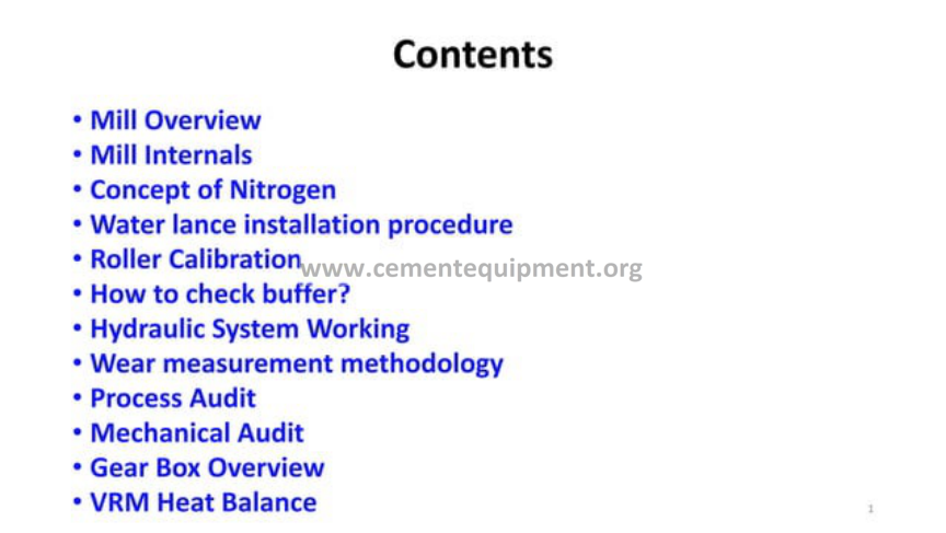
Vertical Roller Mill: Complete Operation Guide
The vertical roller mill is the dominant grinding machine of the modern cement plant, used for raw material grinding, for coal grinding and increasingly for cement grinding, and it is the machine that has displaced the ball mill in most new installations because of its lower specific energy consumption, its compact layout and its ability to dry and grind in a single unit. This article is a complete technical guide to the vertical roller mill, written for operators, process engineers, maintenance staff and plant managers who must understand, operate and maintain the machine: the grinding bed and its formation, the roller and table geometry and the grinding force system, the hydraulic system that loads the rollers, the dam ring that controls the bed, the gas circuit that carries the material and the heat through the mill, the classification of the ground material by the dynamic classifier, the operation of the mill and its control loops, and the maintenance of the machine from the rollers and the table to the gearbox and the hydraulic accumulators. The vertical roller mill is a compact, high-performance machine whose operation is governed by a set of interacting principles, and the plant that understands those principles operates the mill at its optimum, with the minimum specific energy, the maximum throughput and the longest component life.
Principles of the Vertical Roller Mill
The vertical roller mill grinds material between a rotating table and a set of rollers that are pressed against the table by a hydraulic force. The material, fed to the centre of the table, is carried outward by the centrifugal action of the table rotation and is crushed and ground between the roller and the table. The ground material is then picked up by the gas stream flowing upward through the mill, which carries the fine particles to the classifier while returning the coarse particles to the grinding zone.
The grinding in the vertical roller mill is fundamentally different from the impact grinding of the ball mill. The material in the VRM is crushed by the compression and the shear between the roller and the table, in a thin bed of material, rather than by the impact of free-falling media. The grinding process is therefore more energy-efficient, because the energy is applied directly to the material bed rather than being dissipated in the lifting and the tumbling of the media, and the specific energy consumption of the VRM is typically 25 to 35 percent lower than that of the ball mill for the same duty.
The VRM is also a drying machine. The hot gas, drawn through the mill by the mill fan, both carries the ground material to the classifier and dries the moisture in the feed. The VRM can therefore accept raw materials with a moisture content of up to 20 percent or more, drying them in the grinding process, which eliminates the separate drying step required with the ball mill systems. This combination of grinding, drying and classifying in a single machine is the source of the VRM’s compact layout and its operating economy.
The Grinding Bed
The grinding bed is the thin layer of material that lies between the roller and the table during the grinding, and its condition governs everything about the grinding process. The bed must be present for the grinding to occur: if the table is bare and the roller contacts the metal directly, the mill vibrates violently, the metal wears catastrophically and the mill must be stopped. If the bed is too thick, the rollers ride on the material without grinding it effectively, the power draw rises and the grinding efficiency falls.
The formation of the bed depends on the balance between the feed rate, the grinding rate and the removal of the ground material. The feed is delivered to the centre of the table, the table carries the material outward under the rollers, and the material is ground and then pushed over the edge of the table by the incoming feed and by the action of the dam ring. The bed thickness at the grinding zone is set by the height of the dam ring, the table speed, the feed rate and the grinding force.
The stability of the bed is the central operating challenge of the VRM. The mill is operated so that the bed is thin but continuous, typically a few tens of millimetres thick depending on the material, and the control system maintains this state by balancing the feed, the gas flow and the grinding force. The modern mills use the mill vibration and the hydraulic pressure signals as the indicators of the bed condition, and the control system adjusts the process variables continuously to keep the bed in the stable operating window.
Roller and Table Geometry
The grinding elements of the VRM, the rollers and the table, are designed with a specific geometry that sets the grinding action. The rollers are typically cylindrical or conical in profile, and the table is a flat or slightly dished disc, with the roller axes inclined so that the roller rolls on the table with a combination of crushing and shearing action. The contact geometry, the roller width, the roller diameter and the table diameter are the principal design parameters.
The grinding force is transmitted through the roller bearings to the roller tyres, which are the replaceable wearing surfaces of the rollers, and through the table liners, which are the replaceable wearing surfaces of the table. The roller tyres and the table liners are made of the wear-resistant alloys, typically high-chromium cast irons or composite materials, and they are the highest-wear components of the mill. The wear pattern of the tyres and the liners, and the running-in of the new elements to a matched profile, are central to the mill’s performance and its maintenance.
The geometry also determines the grinding efficiency through the pressure distribution in the contact zone. The material is ground in a narrow band at the line of contact between the roller and the table, and the local pressure in this band is extremely high, of the order of several hundred megapascals, which is what makes the VRM an efficient grinder of hard materials. The design of the roller and table profiles is continuously refined by the manufacturers to improve the pressure distribution and the grinding efficiency.
The Grinding Force and the Hydraulic System
The grinding force, which presses the rollers against the material on the table, is applied by the hydraulic system. Each roller is mounted on a lever arm, and the hydraulic cylinder applies a force to the lever arm that presses the roller down onto the table. The grinding force is the sum of the roller’s own weight and the hydraulic force, and it is one of the principal operating variables of the mill.
The hydraulic system is more than a simple cylinder: it is a closed hydraulic circuit with the accumulators, the check valves and the safety systems that protect the mill. The accumulators, charged with nitrogen to a set pressure, act as a spring that absorbs the shock loads when the roller encounters a lump of hard material or a foreign body, allowing the roller to lift momentarily and to pass over the obstruction without transmitting the shock to the mill structure and the gearbox.
The hydraulic pressure is set by the operator according to the material, the target production and the fineness, and the specific grinding pressure, expressed as the force per unit of the grinding surface, is a key operating parameter. The correct grinding pressure gives the maximum grinding efficiency with the minimum vibration; too low a pressure leaves the bed thick and the grinding slow, and too high a pressure over-compresses the bed, wastes energy and can damage the bearings and the tyres.
The Dam Ring
The dam ring is the rim fitted around the outer edge of the grinding table, and its height sets the thickness of the material bed on the table. The material ground on the table is carried outward by the centrifugal action, and it can only leave the table by passing over the dam ring. The higher the dam ring, the thicker the bed on the table and the longer the residence time of the material under the rollers; the lower the dam ring, the thinner the bed and the faster the material passes through the grinding zone.
The dam ring height is therefore the direct mechanical control of the bed thickness, and it is adjusted by the addition or the removal of the segments that make up the ring. The correct dam ring height is found by the optimisation of the mill: a height that is too high produces a thick bed, a high power draw and a risk of mill vibration, while a height that is too low produces a thin bed, poor grinding and excessive wear. The modern mills use the adjustable dam rings that can be set without a major mill stop.
The dam ring also controls the reject rate, the fraction of the material that passes over the edge of the table and falls through the throat into the mill housing for the return to the table. The correct reject rate, typically in the range of 30 to 50 percent of the feed, ensures that the bed is continuously refreshed and that the coarse particles are returned for the further grinding, and the operator reads the reject rate from the mill’s material balance and adjusts the dam ring and the process variables accordingly.
The Gas Circuit and the Mill Fan
The gas circuit of the VRM is the system that carries the material through the mill and provides the drying heat. The hot gas, from the kiln exhaust, the cooler or the hot gas generator, enters the mill through the hot gas duct and flows upward through the nozzle ring and the grinding chamber. The gas velocity at the nozzle ring is high, and it fluidises and lifts the ground material from the table, carrying the fine particles upward to the classifier while the coarse particles fall back to the table.
The gas flow is driven by the mill fan, also called the main exhaust fan or the mill circulating fan, which draws the gas through the mill, the classifier and the mill bag filter or the electrostatic precipitator. The gas flow is one of the principal operating variables: too little gas reduces the lifting and the drying, and too much gas increases the pressure drop and the fan power and can overload the dust collection system.
The gas circuit also includes the mill inlet pressure control, the mill outlet temperature control and the mill inlet temperature control. The inlet temperature is controlled by the hot gas damper and the cold gas damper, which mix the hot gas with the ambient air to achieve the temperature that dries the material without overheating the mill internals. The outlet temperature is controlled to keep the dew point safe and to protect the bag filter, and the mill differential pressure is monitored as the indicator of the internal load and the material flow.
The Nozzle Ring and the Throat
The nozzle ring, also called the louvre ring or the throat ring, is the ring of angled vanes that surrounds the table and through which the gas enters the grinding chamber. The nozzle ring accelerates the gas to the velocity that lifts the material from the table, and the angle of the vanes imparts a tangential component to the gas flow that assists the transport of the material around the mill. The nozzle ring is one of the highest-wear components of the mill, and it is made of the wear-resistant materials and is replaced on a schedule.
The gas velocity at the nozzle ring sets the separation between the material carried up into the mill and the material that falls back through the throat. The coarse particles, which are too heavy for the gas to lift, fall through the throat into the mill housing, are collected by the reject conveyor and are returned to the table with the fresh feed. The fine particles are carried upward into the classifier, and the balance between the lifting and the fall-back is the mechanism by which the mill maintains the correct bed and the correct reject rate.
The condition of the nozzle ring is critical to the mill performance. The wear of the vanes widens the throat, reduces the gas velocity and changes the lifting behaviour, and the build-up of the material in the throat restricts the flow and raises the mill pressure drop. The inspection and the maintenance of the nozzle ring, including the replacement of the worn vanes and the cleaning of the throat, is a standard part of the mill maintenance program.
Classification in the VRM
The classification of the ground material is performed by the dynamic classifier, mounted at the top of the mill, which separates the fine product from the coarse material. The classifier consists of a set of rotating vanes, driven by a separate motor and gearbox, which create a radial air flow that deflects the coarse particles back into the mill while allowing the fine particles to pass through to the product outlet. The classifier speed sets the fineness of the product.
The dynamic classifier is a high-efficiency separator of the same family as the third-generation separators used in the ball mill circuits, and its separating performance is described by the same parameters: the cut size, the sharpness of the separation and the bypass. The classifier speed is the principal control of the product fineness, and the modern control systems adjust the classifier speed continuously to maintain the target Blaine or residue.
The classifier is also a maintenance item. The rotating vanes wear by the abrasion of the material, the bearings and the seals require attention, and the classifier gearbox is a major mechanical component with its own lubrication and its own monitoring. The condition of the classifier directly affects the product quality, and the inspection and the maintenance of the classifier is scheduled alongside the mill maintenance.
Grinding in the VRM vs the Ball Mill
The comparison of the VRM with the ball mill is the central economic question of grinding system selection, and the VRM wins on several fundamental points. The specific energy consumption of the VRM is typically 25 to 35 percent lower, because the grinding energy is applied directly to the material bed rather than being dissipated in the lifting of the media. The VRM also dries the feed in the grinding process, eliminating the separate drying step, and it classifies the product internally, eliminating the external separator circuit.
The VRM has a smaller footprint and a lower building height than the ball mill, and it is started and stopped more quickly, which makes it the preferred machine for the plants that operate flexibly. The noise and the dust are lower, and the mill can be controlled more precisely because the response time of the VRM to the process changes is short compared with the ball mill’s large thermal and material inertia.
The principal disadvantage of the VRM is its sensitivity to the feed and its dependence on the correct bed: the mill is less tolerant of the hard lumps, the foreign bodies and the changes in the material moisture, and it requires a higher standard of operation and control. The VRM is also a more complex machine mechanically, with the hydraulic system, the separator and the mill gearbox requiring specialist maintenance. The modern plant weighs these factors against the energy saving, and the VRM is now the default choice for the raw mill and the coal mill, with the cement mill application growing as the operating experience accumulates.
Operation of the VRM
The operation of the VRM is governed by the control of a small number of interacting variables: the feed rate, the grinding force, the gas flow, the gas temperature, the classifier speed and the reject rate. The operator, or the automatic control system, balances these variables to maintain the mill in the stable operating window where the bed is thin and continuous, the vibration is low, the power draw is at the target, the outlet temperature is correct and the product fineness meets the target.
The start-up of the VRM follows a defined sequence. The mill is started with the table rotating, the gas flow is established, the mill is warmed up to the operating temperature, the feed is started at a low rate and is increased gradually while the operator watches the mill power, the differential pressure and the vibration. The mill is brought to the full operating point over a period of minutes, with the process variables adjusted in step.
The shut-down follows the reverse sequence: the feed is reduced and stopped, the mill is purged with the gas to empty the grinding chamber and the classifier, the mill is stopped and the gas flow is reduced. The correct execution of the start-up and the shut-down, and the correct handling of the trips and the process upsets, is the core of the operator’s skill, and the trained operator protects the mill from the conditions that damage the bed, the tyres, the gearbox and the hydraulics.
Mill Vibration and Its Causes
Mill vibration is the principal symptom of the disturbed operation of the VRM, and its analysis is the basis of the troubleshooting. The vibration is measured by the accelerometers mounted on the mill housing and on the roller arms, and the mill is protected by the vibration interlocks that trip the mill when the vibration exceeds the set limit. The vibration level in the normal operation is low and steady, and the mill that vibrates heavily is telling the operator that the process is out of balance.
The common causes of the vibration are the loss of the bed, the over-thickening of the bed, the entry of the hard material or the foreign bodies, the incorrect grinding force, the moisture fluctuations in the feed and the instability of the gas flow. Each cause has a characteristic signature in the vibration trace and in the process signals, and the experienced operator recognises the signature and responds with the correct correction: adjusting the feed, the grinding force or the gas flow, or stopping the mill when the condition cannot be controlled.
The prevention of the vibration is the prevention of the mill damage. A mill that vibrates repeatedly suffers the fatigue of the structure, the damage to the roller bearings and the gearbox, and the accelerated wear of the tyres and the liners. The plant that maintains the mill in the stable operating window, that responds correctly to the disturbances and that investigates the repeated vibration events, protects the mill’s components and its availability.
Mill Differential Pressure and Internal Load
The differential pressure across the mill is the pressure drop of the gas flowing through the mill, and it is the principal indicator of the internal material load. The differential pressure rises as the material load in the mill rises, because the denser gas stream and the higher material concentration increase the resistance to the flow. The operator uses the differential pressure as the measure of the mill’s internal state, alongside the mill power draw.
The differential pressure is controlled by the balance between the feed and the gas flow. If the feed rises without a corresponding rise in the grinding capacity, the material load in the mill rises, the differential pressure rises and the mill can eventually overload and trip. The control system adjusts the feed rate to hold the differential pressure at the set point, and the operator monitors the trend as the indicator of the grinding efficiency and the mill condition.
The differential pressure also responds to the mechanical condition of the mill. The wear of the nozzle ring and the build-up in the throat change the pressure drop, and the comparison of the pressure at a given feed and gas flow with the historical trend reveals the deterioration. The daily review of the differential pressure trends, in the same way as the review of the power draw and the vibration, is a standard part of the mill monitoring.
Mill Outlet Temperature and Drying
The mill outlet temperature is the indicator of the drying performance and the heat balance of the mill. The hot gas entering the mill at a temperature set by the hot gas damper and the cold gas damper gives up its heat to the material, drying the moisture, and leaves the mill at the outlet temperature. The outlet temperature is typically controlled in the range of 80 to 120 degrees Celsius, depending on the application and the downstream equipment, and it is kept above the dew point to prevent the condensation in the bag filter.
The drying capacity of the mill is set by the inlet temperature and the gas flow. A feed with a high moisture content requires a higher inlet temperature or a higher gas flow to evaporate the moisture, and the mill has a maximum drying capacity defined by the design. The mill that is drying-limited cannot grind at its full capacity, and the plant must manage the feed moisture and the gas temperature to keep the mill within its drying capability.
The outlet temperature also protects the equipment. A too-high outlet temperature damages the bag filter and can ignite the coal dust in the coal mill, and a too-low outlet temperature causes the condensation, the build-up and the corrosion. The temperature control is therefore a safety function as well as a process function, and the operator monitors the outlet temperature continuously, with the interlocks that trip the mill on the high and the low temperatures.
Coal Grinding in the VRM
The VRM is the standard machine for coal grinding in the modern cement plant, because its high drying capacity handles the high-moisture coals, its closed system contains the coal dust, and its low specific energy makes it economical. The coal mill operates with the same principles as the raw mill, but with a critical safety dimension: the coal is a flammable and explosive material, and the mill must be operated and maintained to prevent the ignition and the explosion.
The coal mill safety measures include the inert atmosphere control, where the oxygen content in the mill is kept below the limit that supports the combustion, the temperature limits that prevent the ignition of the coal dust, the spark detection and the fire suppression systems, and the explosion relief panels that protect the mill and the building. The operation of the coal mill is governed by a dedicated safety logic that interlocks the mill with the temperature, the oxygen and the fire detection signals.
The maintenance of the coal mill follows the same program as the raw mill, with the additional safety dimension. The inspections are carried out after the mill has been purged and the atmosphere has been tested, the coal dust is cleaned from the mill internals on a schedule, and the electrical and the mechanical equipment in the coal grinding area is maintained to the explosive atmosphere standards. The plant that operates and maintains the coal mill to the safety standards protects both the equipment and the personnel.
Key Operating Parameters of the VRM
The management of the VRM is supported by a small set of measurable parameters. The table below summarises the typical values for a modern raw mill or cement mill VRM and the meaning of a deviation from the normal range.
| Parameter | Typical normal range | Meaning if below range | Meaning if above range |
|---|---|---|---|
| Specific grinding pressure | 0.6 – 1.0 MPa | Thick bed, slow grinding | Over-compression, high wear, vibration |
| Table speed | Set by gearbox, fixed | – | – |
| Dam ring height | 70 – 120 mm typical | Thin bed, poor grinding | Thick bed, high power, vibration risk |
| Reject rate | 30 – 50 percent of feed | Possible over-grinding | Poor classification or worn nozzle ring |
| Mill differential pressure | 40 – 70 mbar | Low internal load | Overload; risk of trip |
| Mill outlet temperature | 80 – 120 degrees C | Condensation risk in bag filter | Filter damage or coal dust ignition |
| Classifier speed | Set for target fineness | Coarser product | Finer product, higher pressure drop |
| Specific energy, raw mill | 18 – 25 kWh per tonne | Excellent | Worn elements or wrong operating point |
The value of the table is that it converts the qualitative description of the VRM into quantitative limits that the operator and the process engineer can measure, trend and act on.
The Gearbox and the Main Drive
The VRM is driven through a large, specialised gearbox that transmits the power from the electric motor to the grinding table. The gearbox is one of the most critical and most expensive components of the mill, and it carries the full grinding load in addition to the drive torque: the grinding force is transmitted through the table into the gearbox, so the gearbox must support both the rotational drive and the vertical load. The gearboxes are typically of the bevel-planetary type, with a large diameter and a high load capacity.
The gearbox lubrication and cooling are critical to its life. The gearbox is equipped with a lubrication system that filters, cools and circulates the oil, and the oil condition, the oil temperature and the bearing vibrations are monitored continuously. The gearbox is protected by the interlocks that trip the mill on the high oil temperature, the low oil pressure and the high vibration, and the condition of the gearbox is monitored with the oil analysis and the vibration analysis on a scheduled basis.
The gearbox is also the point where the mill’s foundation interacts with the mill. The gearbox is bolted to the mill foundation, and the foundation bolts and the gearbox support are inspected and re-torqued on a schedule. The gearbox overhaul is a major event in the mill’s life, typically carried out every 60,000 to 100,000 operating hours, and the planning of the overhaul, the spare parts and the specialised labour is a significant part of the mill’s maintenance planning.
Roller Bearing Maintenance
The roller bearings carry the grinding load and the shock loads of the grinding process, and their condition is critical to the mill’s availability. The roller bearings are spherical roller bearings mounted in the roller assembly, and they are lubricated with the grease or the oil system that is monitored for the temperature and the condition. The bearing temperature is monitored continuously, and the high bearing temperature is a trip signal that protects the bearing and the roller assembly.
The roller assemblies are the principal maintenance items of the mill. The tyres wear, the bearings wear, and the seals deteriorate, and the roller assembly is removed for the overhaul on a scheduled basis. The overhaul includes the replacement of the tyres, the inspection and the replacement of the bearings, the renewal of the seals and the re-pressurisation of the accumulator systems, and the reassembly of the roller with the correct preload and the correct clearance.
The condition monitoring of the roller bearings includes the vibration analysis, the oil or the grease analysis and the temperature trends, and the maintenance team uses the data to schedule the roller overhauls before the failure. A bearing failure in service is a major event, with the damage to the roller assembly, the table and the gearbox, and the prevention of the bearing failure through the condition monitoring is one of the highest-value maintenance activities in the plant.
The Mill Housing and the Reject System
The mill housing contains the grinding chamber and the classifier, and it provides the structure that supports the mill and the gas ducts. The housing is a large fabricated steel structure with the internal wear protection, the inspection doors and the explosion relief panels in the coal mill. The wear protection of the housing, in the zones where the material and the gas impinge, is a maintenance item that is renewed on a schedule.
The reject system collects the coarse material that falls through the throat and returns it to the table with the fresh feed. The rejects pass through the reject valves and the reject conveyor, and the reject flow is metered so that the operator can see the reject rate. The reject system is a wear item, and the rejects are abrasive, so the reject chutes and the conveyor are made of the wear-resistant materials and are inspected regularly.
The reject rate is one of the most useful operating signals of the VRM. A rising reject rate at a constant feed and gas flow indicates the wear of the nozzle ring, the thickening of the bed or a change in the feed material, and the correction of the cause restores the mill to the efficient operating point. The plant that monitors the reject rate trends catches the developing problems early and avoids the loss of efficiency that follows the unaddressed deterioration.
The Mill Fan and the Dust Collection
The mill fan, the main fan that draws the gas through the mill, is a large induced-draft fan with a variable speed drive. The fan is one of the largest power consumers of the grinding system, and its efficiency and its condition are a significant part of the mill’s energy budget. The fan is monitored with the vibration analysis and the bearing temperature, and the fan impeller is inspected and cleaned on a schedule, because the dust build-up on the impeller unbalances the fan and raises its power consumption.
The dust collection system, the mill bag filter or the electrostatic precipitator, cleans the gas before it is exhausted to the atmosphere. The bag filter receives the product from the mill, and the filtered dust is returned to the product conveyor. The condition of the bags, the cleaning system and the temperature control are critical: the mill outlet temperature must be kept above the dew point to prevent the condensation in the filter, and the filter is protected by the interlocks and the fire detection in the coal application.
The fan and the filter interact with the mill through the gas flow and the pressure. The mill differential pressure and the filter differential pressure are monitored, and the rising filter differential pressure indicates the blocked bags, which raises the fan power and can limit the mill capacity. The maintenance of the fan and the filter is scheduled to keep both at their best condition, and the energy audit of the grinding system includes the fan and the filter as significant consumers.
Maintenance Planning and Spares
The maintenance of the VRM is planned on the basis of the wear predictions and the condition monitoring. The principal wear items, the roller tyres, the table liners and the nozzle ring, have predictable wear lives measured in thousands of operating hours, and the maintenance plan schedules their replacement at the mill stops. The condition-monitored items, the gearbox, the roller bearings and the fan, are maintained on the basis of the vibration and the oil analysis results.
The spare parts strategy for the VRM is critical, because the lead times for the major components are long. The plant carries the roller tyres, the table liners, the nozzle ring segments, the seals and the bearings as the stock items, and it plans the major components, the gearbox parts and the roller assemblies, on the basis of the overhaul schedule. The planning of the spares, with the lead times and the budget, is a significant part of the mill’s asset management.
The maintenance records are the basis of the planning. The wear measurements, the inspection results, the vibration trends and the oil analysis results are recorded in the mill’s history file, and the trends are reviewed at each planning cycle. The plant that maintains the records faithfully, and that uses them to plan the interventions, operates the mill with the minimum downtime and the maximum component life, and it avoids the emergency repairs that dominate the plants without the discipline.
Optimisation of the VRM
The optimisation of the VRM is a continuous activity that combines the process tuning with the mechanical condition. The process optimisation finds the operating point that gives the target product at the minimum specific energy: the feed rate, the grinding force, the classifier speed and the gas flow are adjusted against the measured product fineness, the power draw and the reject rate, and the optimum is tracked as the material and the conditions change.
The mechanical condition interacts with the process optimisation. The wear of the tyres and the liners changes the grinding action, and the mill must be re-optimised as the wear progresses. The running-in of the new tyres and the liners, the adjustment of the dam ring and the correction of the nozzle ring condition are all part of the optimisation loop, and the plant that treats the mill as a system, rather than as a collection of parts, achieves the best result.
The optimisation is supported by the measurements and the analyses: the product fineness distribution, the material moisture, the mill power draw, the gas flows and the temperatures are all recorded and analysed, and the improvements are verified against the baseline. The modern plants use the advanced control systems that optimise the mill automatically, and the process engineers review the performance on a scheduled basis to identify the next improvement.
Future Developments in VRM Technology
The VRM technology continues to develop in response to the industry’s demands for the lower energy, the higher capacity and the greater flexibility. The grinding elements are improving with the new wear materials and the new profiles that increase the grinding efficiency and the life. The gearbox technology is improving with the higher power density and the better reliability, and the classifiers are improving with the sharper separation and the lower pressure drop.
The digitalisation is transforming the operation of the VRM. The mills are fitted with the dense instrumentation that feeds the advanced control systems, the digital twins of the mill predict the performance and the wear, and the predictive maintenance uses the data to plan the interventions. The integration of the mill with the plant-wide energy management, and with the alternative fuel and the decarbonisation strategies, is shaping the role of the VRM in the future cement plant.
The outlook for the VRM is for a machine that is more efficient, more reliable and more flexible, operating closer to its optimum for more of its life. The fundamentals described in this article, the grinding bed, the roller and table geometry, the hydraulic system, the dam ring, the gas circuit and the classifier, will remain the foundations of the design, and the trained operator and the engineer will remain the decisive factor in extracting the value from the machine.
Frequently Asked Questions
What is a vertical roller mill and how does it work?
The vertical roller mill grinds material between a rotating table and hydraulically loaded rollers, with the material carried outward by the table rotation and crushed in a thin bed. The ground material is lifted by the gas stream and classified by a dynamic classifier at the top of the mill.
Why is the VRM more energy-efficient than the ball mill?
The VRM applies the grinding energy directly to the material bed through the compression between the rollers and the table, instead of dissipating it in the lifting and tumbling of the grinding media. The specific energy consumption is typically 25 to 35 percent lower.
What is the grinding bed and why is it important?
The grinding bed is the thin layer of material between the rollers and the table. It must be present and stable: a bare table causes severe vibration and wear, and a bed that is too thick wastes energy. The bed is controlled by the feed, the gas flow, the grinding force and the dam ring.
What does the hydraulic system do?
The hydraulic system applies the grinding force to the rollers through cylinders and lever arms. The nitrogen-charged accumulators act as springs that absorb shock loads when the rollers pass over hard material, protecting the mill structure, the bearings and the gearbox.
What is the dam ring and how is it adjusted?
The dam ring is the rim around the outer edge of the grinding table that sets the bed thickness. Its height is adjusted by adding or removing segments, and the correct height gives the optimum bed with the correct reject rate and the minimum specific energy.
What are the main maintenance items of the VRM?
The main wear items are the roller tyres, the table liners and the nozzle ring, which are replaced on a schedule based on the wear predictions. The critical mechanical items are the gearbox and the roller bearings, which are maintained on the basis of the condition monitoring.
Summary
The vertical roller mill is the grinding machine of the modern cement plant, and this article has covered it completely: the principles of the bed grinding that make the VRM efficient, the roller and table geometry and the grinding force system, the hydraulic system and its accumulators, the dam ring that controls the bed and the reject rate, the gas circuit and the mill fan that carry the material and the heat, the nozzle ring and the throat that set the internal classification, the dynamic classifier that sets the product fineness, the comparison with the ball mill that explains the VRM’s dominance, the operation of the mill with its control loops and its start-up and shut-down sequences, the vibration, the differential pressure and the outlet temperature that the operator reads as the mill’s vital signs, the coal grinding application with its safety dimension, and the maintenance of the machine from the tyres and the liners through the gearbox and the bearings to the fan and the filter. The maintenance and the optimisation of the VRM rest on the measured trends: the wear of the tyres and the liners, the reject rate, the vibration, the differential pressure and the specific energy, all recorded, trended and acted upon. The future of the VRM is one of the better materials, the digital twins and the predictive maintenance, but the fundamentals remain the trained operator and the disciplined maintenance team. The plant that understands the VRM, that operates it in the stable window and that maintains it on the planned cycle, will grind its raw material, its coal and its cement at the minimum cost and the maximum availability, and it will enjoy the full value of the machine that has become the heart of the cement grinding plant.
Get this cement file + the full 931-file package
$249 — one-time purchase, instant download, lifetime access
This file is part of the Complete Cement Technical Package (931 files) available from cementequipment.org. Respective rights holders; library copy for the licensed single user.