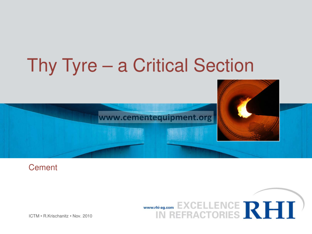
Kiln Tyre: The Critical Section Explained
The tyre of a rotary kiln is arguably the single most critical mechanical section of the entire pyroprocessing line, yet it is also the section most frequently misunderstood, under-instrumented and under-maintained in the cement industry. In this article we take the tyre apart piece by piece: what it actually does, how it is designed as a shrunk ring that transmits the entire weight of the kiln shell and charge through the support rollers, why its diameter must be roughly three to five times the shell diameter to develop the stiffness it needs, how thermal expansion governs the fit between the tyre and the shell, what happens during heating and cooling at controlled rates around 100 degrees Celsius per hour, how tyre creep indicates whether the interface is healthy, why ovality measurement has become the modern diagnostic tool, and finally what a serious preventive maintenance program looks like. This is a field engineer’s treatment of the subject, written for kiln maintenance engineers, mechanical supervisors, rotating equipment specialists and plant technical managers who have to keep the kiln mechanically sound for thousands of operating hours. The tyre is not just a big steel ring. It is the load path, the thermal buffer, the sliding bearing surface and the deformation sensor of the whole kiln mechanical system. Understanding it thoroughly is a prerequisite for reliable, high-availability pyroprocessing.
What a Kiln Tyre Actually Does
The kiln tyre, sometimes called a riding ring, is a forged or rolled steel ring mounted around the kiln shell at each support station. Its primary job is to transmit the vertical load of the shell, refractory, material charge and coating from the rotating kiln down onto the support rollers through the sliding or oscillating support roller assemblies. Modern kilns typically have between three and six support stations, and each station carries a tyre. The load at each station can be enormous. For a modern 5000 tpd kiln with a shell diameter around 4.8 metres and a length around 72 metres, the reaction at each support can easily reach several hundred tonnes, and the total dead weight of shell, brick and fill can approach two thousand tonnes. The tyre distributes this concentrated line reaction over a broad band of the shell so that the shell does not collapse locally under the roller pressure.
The tyre therefore acts as a stiffening ring. Left alone, a thin cylindrical shell of the type used in kiln construction would deform locally into an oval under each roller reaction, and the flexing would rapidly fatigue the shell plate, the refractory would crack and fall, and the oval shape would quickly become permanent. By clamping a massive ring around the shell, the tyre resists radial deflection and keeps the cross-section essentially circular at the support plane. This is why the tyre is considered a critical section: a failure of the tyre, or a loosening of the fit, cascades immediately into shell ovality, refractory damage, roller damage and ultimately a mechanical trip of the kiln.
Additionally, the tyre provides the hard, wear-resistant surface against which the support rollers roll. The interface between tyre bore and shell outside surface is a sliding joint by design. The tyre does not rotate with the shell at exactly the same surface speed; instead it rotates slightly slower, and the resulting relative motion is called tyre creep. The bore of the tyre and the outside surface of the shell must remain in good sliding contact so that the creep is even and predictable. If the contact becomes uneven, the tyre can slip violently, a condition known as tyre slide or kiln tyre slippage, which produces characteristic bright sparks, loud screeching, and rapid local wear of both surfaces.
The Shrunk Ring Design Principle
Most modern kilns use a loose-fit or shrunk-on tyre design where the tyre is a plain cylindrical ring mounted around the shell with a defined diametral clearance and held in place axially by two retaining rings or stops welded or bolted to the shell. The phrase “shrunk ring” describes the thermal and mechanical philosophy of the design: the tyre is nominally larger than the shell diameter at ambient temperature, and when the kiln is heated the shell expands outward faster than the tyre because the shell is hotter and its thermal growth is not balanced by the tyre’s own expansion. The result is that the clearance closes as the kiln warms up, and at normal operating temperature the tyre is effectively clamped onto the shell by the thermal expansion of the shell itself.
The design must be carefully calculated so that at operating temperature the interference, and hence the contact pressure, is sufficient to transmit the radial load without the tyre lifting off the shell on the top side, but not so great that the shell is crushed or that differential expansion cracks the shell plate or welds. The classic design rule is that the inside diameter of the tyre must be larger than the outside diameter of the shell by a specific cold clearance, and that the tyre width must be sufficient to spread the load. The cold diametral clearance is typically in the range of 0.1 to 0.3 percent of the shell diameter, depending on the manufacturer and on the expected thermal differential between shell and tyre during operation.
Because the tyre is a massive ring, its own temperature lags behind the shell temperature. The shell at the support plane is protected by refractory and coating, but it still runs hotter than the tyre surface, which is exposed to ambient air and is continuously cooled by the support rollers. The temperature differential between the shell and the tyre at a given support station is the fundamental driver of the interference fit. During stable operation this differential is relatively constant, so the fit is constant. During a kiln shut-down or start-up, the differential changes dramatically, and it is during these transients that the fit is most at risk.
Tyre Diameter in Relation to the Shell
One of the most repeated rules in kiln mechanical design is that the tyre diameter should be between three and five times the shell wall thickness in terms of flexural behaviour, and more practically, that the tyre is a deep ring whose cross-sectional depth is a significant fraction of the shell diameter. A common simplification quoted in the field is that the tyre outside diameter is typically on the order of 1.5 to 1.7 times the shell diameter, and the radial depth of the tyre cross-section is a substantial fraction of the shell radius. The deeper the tyre, the stiffer the ring, and the better it resists ovalising deformation under the roller reaction.
Let us be precise about what the “three to five times” rule actually refers to, because it is often misquoted. The rule in classical ring theory and in kiln design guidance states that the bending stiffness of the tyre, which depends on the cube of the radial thickness, must be high enough that the tyre’s own elastic ovality under load remains small. In practice, manufacturers design the tyre radial thickness so that the tyre cross-section area and moment of inertia produce a calculated ovality under full load that stays below roughly 1.0 to 2.0 millimetres of diametral deflection for modern kilns. Because bending stiffness scales with the cube of thickness, a tyre that is too thin will flex grossly, transferring the flexing down into the shell and creating the very ovality problems the tyre is meant to prevent.
For the maintenance engineer, the practical implication is that the tyre is dimensionally enormous. A 4.8 metre diameter kiln will carry tyres whose outside diameter approaches 7 to 8 metres, weighing 50 to 90 tonnes each. Lifting, machining, inspection and replacement of such components require cranes, special transport, and careful planning. The sheer size is why tyre maintenance is often done in place, with the kiln supported on hydraulic jacks and the tyre machined using portable machines, rather than removed for workshop repair.
Materials and Manufacture of Tyres
Kiln tyres are forged or rolled from carbon steel or low-alloy carbon steel, typically in the range of 0.4 to 0.5 percent carbon, chosen to balance strength, toughness and wear resistance. The steel is refined to control sulphur and phosphorus, then forged into a ring blank and rolled to final size. Because the tyre operates at elevated temperature and must resist both static bending stress and rolling contact wear from the support rollers, the microstructure is usually normalised or quenched and tempered to give a yield strength in the range of 350 to 550 MPa and a good balance of ductility.
The bore of the tyre is machined to a controlled diameter with a surface finish that allows clean sliding contact with the shell. The outside surface, which contacts the support rollers, is machined or turned to maintain roundness and is the surface that determines the running quality of the kiln. Over the life of the tyre, the outside surface wears, and the tyre can be re-machined one or more times before the cross-section becomes too thin. The number of allowable re-machines is a design parameter: each machining pass removes material, reducing the ring depth and therefore the stiffness, until the tyre must finally be replaced.
The support rollers, which are hardened steel wheels typically twice the tyre surface hardness, run against the tyre outside face and themselves wear. Both the tyre and the rollers must maintain their relative diameters so that the surface speeds match, otherwise sliding wear accelerates. The design intent is that the tyre wears faster than the rollers in a controlled manner, so that periodic re-machining of the tyre and occasional re-grinding of the rollers keeps the pair running true.
Thermal Expansion and the Fit
Thermal expansion is the physical phenomenon that makes the tyre fit work. The coefficient of thermal expansion for the carbon steel used in kiln shells and tyres is on the order of 12 x 10^-6 per degree Celsius. For a 4.8 metre diameter shell, every 100 degrees Celsius of temperature change produces roughly 5.8 millimetres of diametral growth. This is an enormous number compared with the cold clearance between tyre and shell, which is typically only a few millimetres. It follows that the temperature differential between shell and tyre controls everything about the fit.
During cold state, the kiln shell sits inside the tyre with a defined cold clearance. The tyre carries the shell on two support rollers, and the shell and tyre do not contact each other over the full circumference. As the kiln is heated, the shell expands radially outward, and because the shell is hotter than the tyre, the shell grows faster. At some point during the heat-up the shell comes into contact with the tyre bore at the top, and from then on the shell presses against the tyre. As the temperature differential stabilises at the full operating level, the interference becomes maximum, and the tyre is driven by friction at the contact interface. In this condition the shell is held circular by the tyre, and the load path through the roller is stiff and even.
The critical period for the fit is therefore the transient. During heat-up, if the temperature differential is allowed to overshoot, the interference can become too large, producing very high contact stresses and even plastic deformation of the shell under the tyre. During cool-down, the shell shrinks faster than the tyre, and if the kiln is allowed to cool too quickly the fit opens up, the tyre becomes loose, and it can rotate freely or rock on the shell, destroying the retaining ring welds and galling the bore. This is exactly why controlled heating and cooling rates are so important, and why the operator is instructed to respect the maximum rate of temperature change.
Heating and Cooling Rates Around 100 Degrees per Hour
The standard operational rule in the cement industry is to limit the rate of change of shell temperature, and hence the rate of change of the fit, during start-up and shut-down. A commonly cited figure is that the kiln must not be heated or cooled faster than about 100 degrees Celsius per hour when the refractory is in place, and that figure is even more restrictive for the mechanical integrity of the tyre interface. In practice, many plants heat up at 50 to 100 degrees Celsius per hour in the lower temperature range, and reduce the rate even further as temperatures rise, particularly in the burning zone where the brick is most sensitive.
Why is the rate so important for the tyre? Because the shell and the tyre have very different thermal masses. The shell is a relatively thin plate, typically 40 to 80 millimetres thick, with a low thermal mass, so it responds quickly to changes in process temperature. The tyre is a massive ring whose radial depth can be several hundred millimetres, so it responds very slowly. If the process temperature climbs too quickly, the shell heats up, expands and presses against a tyre that is still cold. The differential between shell temperature and tyre temperature becomes large, and the interference becomes large. If the differential becomes extreme, the contact pressure can exceed the yield stress of the shell material in the region of the tyre, producing a permanent local deformation, or “piping”, of the shell.
Similarly, during a rapid cool-down the shell contracts quickly and the tyre, still hot and therefore still large, is suddenly loose. The loose tyre can shift axially, hammer against the retaining stops, and produce exactly the kind of mechanical damage that shows up as bright orange spots on the shell at the tyre during the next heat-up. The discipline of controlled heating and cooling is therefore a direct protection of the tyre interface, and it is one of the cheapest insurance policies available to the plant. The 100 degrees per hour figure appears repeatedly in kiln operating manuals, and experienced operators treat it as a hard ceiling rather than a recommendation.
Key Design and Operating Parameters
The practical management of the tyre system rests on a small set of measurable parameters with well-defined normal ranges. The table below summarises the typical values for a modern rotary kiln and the meaning of a deviation from each normal range. The values are indicative and vary with kiln size, manufacturer and operating practice, but they illustrate the order of magnitude that the maintenance team works with every day.
| Parameter | Typical normal range | Meaning if below range | Meaning if above range |
|---|---|---|---|
| Cold diametral clearance, tyre bore to shell | 0.1 – 0.3% of shell diameter | Fit too tight; risk of seizure and shell piping | Fit too loose; risk of rocking and slide |
| Heating / cooling rate | 50 – 100 degrees C per hour | Longer start-up, low thermal stress | Excessive thermal differential; damaged fit |
| Tyre creep speed at surface | 5 – 20 mm per minute | Creep near zero indicates tight, sticking fit | High creep indicates open fit and sliding |
| Ovality at support station | 0.1 – 0.5% of shell diameter | Very stiff, controlled roundness | Shell flexing; refractory and shell damage |
| Shell temperature beside tyre | 260 – 340 degrees C typical | Possible loose fit and ambient air ingress | Interface overheating; slide or refractory loss |
| Tyre outside surface wear | Rebuilt at design wear limit | – | Reduced ring depth; reduced stiffness |
The value of this table is that it converts the qualitative description of the tyre system into quantitative operating limits. Each parameter has a measurement method, a normal range and a response when the limit is exceeded, and it is this structure that turns tyre management from folklore into engineering.
Tyre Creep and the Health of the Interface
Tyre creep is the small, continuous relative motion between the tyre bore and the shell outside surface that occurs because the tyre, as a free ring driven by friction, tends to rotate at a slightly different angular speed than the shell. In a healthy installation the creep is a few millimetres per revolution, or expressed differently, a creep speed of the order of 10 to 20 millimetres per minute at the tyre surface, and it is steady and uniform around the circumference. Measuring creep is one of the oldest and most valuable diagnostic checks in kiln maintenance.
A normal tyre creeps relative to the shell at a fairly constant rate because the driving friction at the contact is uniform. If the creep rate drops to zero, the tyre is gripping the shell tightly, which means the interference is very high; this often coincides with bright red spots on the shell under the tyre and indicates that the fit is too tight. If the creep rate increases dramatically, the tyre is sliding freely, which means the fit has opened up; this coincides with cold spots on the shell under the tyre, squealing, and sometimes visible slipping of the tyre relative to the shell. Both extremes are dangerous, and the creep measurement gives the maintenance team a direct, non-destructive picture of the fit condition at each support station.
Creep is normally measured during operation using a simple but effective method. A chalk or paint mark is placed across the tyre and shell interface at a convenient position, and the time for the mark on the shell to travel a full circumference relative to the mark on the tyre is timed with a stopwatch. From the timing and the tyre circumference, the creep speed in millimetres per minute is calculated. Periodic creep measurements, logged and trended for each tyre, reveal the slow drift of fit condition that accompanies shell wear, tyre wear and coating changes, and they provide the warning that a tyre is heading toward a slide long before the slide actually happens.
Tyre Slide and Its Causes
Tyre slide, also known as tyre slippage, is the condition where the tyre rotates with the shell at zero relative creep, then suddenly breaks free and rotates at nearly the shell speed, producing violent noise, sparking, and heavy local wear. The mechanism is a loss of lubricating film at the interface combined with high friction. In a normal interface the shell surface and tyre bore are separated by a very thin film of oxidation and graphite-like carbon, often deliberately maintained by applying grease to the shell at the tyre once per shift. If this film is lost, the metal-to-metal contact becomes dry, friction rises, and the contact alternates between sticking and sliding.
The stick-slip behaviour is what makes tyre slides so damaging. When the tyre sticks, it is dragged along with the shell and its inertia builds up. When it finally slips, the stored elastic energy releases suddenly, and the tyre impacts and scrapes over the shell surface, wearing the bore, heating the interface, and generating the characteristic noise that carries across the whole plant. Repeated slides rapidly wear the tyre bore and shell surface out of round, and the out-of-roundness then causes further sliding, in a destructive feedback loop.
The causes of tyre slide are well known. First, insufficient or poor-quality lubricant at the interface, or too long an interval between greasing. Second, a fit that has become too tight because of heavy coating or because the shell has crept outward, which raises the friction torque. Third, an uneven gap caused by an out-of-round tyre or a deformed shell. Fourth, misalignment of the support rollers that tilts the load distribution. The immediate remedy for a slide is to stop the kiln, cool it under control, clean and re-lubricate the interface, and inspect both the tyre bore and the shell for damage. The long-term remedy is to correct the fit by machining the bore or re-machining the tyre outside diameter.
Ovality and Its Measurement
Ovality is the deviation of the kiln cross-section from a true circle at a given plane, measured as the difference between the maximum and minimum diameters at that plane. The tyre exists to control ovality, so ovality measurement is the direct test of whether the tyre is doing its job. Ovality is measured at the shell surface immediately beside the tyre, or at the tyre outside surface itself, using a device that continuously records the radial displacement of the surface as the kiln rotates. Modern plants use laser or induction-based ovality meters that give a continuous trace over several revolutions.
Normal elastic ovality for a modern kiln is small, typically of the order of 1 to 5 millimetres depending on the diameter, the shell thickness, and the position along the kiln. The ovality at a support station is heavily influenced by the tyre fit: a tight tyre produces small ovality, a loose tyre produces larger ovality because the shell is free to flex inside the ring. When ovality exceeds design values, the consequences appear rapidly: the refractory at the affected station is crushed and spalls because the brick is compressed on the minor axis and released on the major axis twice per revolution, and the shell itself begins to fatigue. Ovality readings taken at regular intervals and trended are therefore among the most sensitive early indicators of tyre interface problems.
There is a well-known rule of thumb in kiln inspection that the ovality at any plane should not exceed about one percent of the kiln diameter as an absolute maximum, with good installations operating well below this. Modern guidance and manufacturer recommendations are stricter, often targeting maximum ovality at support stations in the range of 0.5 percent of the diameter or less. When ovality exceeds the limit, the maintenance response is to inspect the tyre fit, check the shell thickness by ultrasonic testing, verify the support roller alignment, and if necessary re-machine the tyre to restore the correct interference.
Support Rollers and the Load Path
The tyre does not work alone. Beneath each tyre, two support rollers carry the kiln, positioned symmetrically at an included angle typically in the range of 60 to 90 degrees between the roller contact lines. The load from the tyre is transmitted through rolling contact into the rollers, then through the roller shafts and bearings into the concrete foundations. The geometry of this arrangement determines the vertical and horizontal load components and the thrust behaviour of the kiln.
The support rollers are hardened, typically to a surface hardness of 50 to 60 HRC, while the tyre surface is softer, typically 30 to 40 HRC. This deliberate hardness differential means that the tyre wears preferentially, protecting the more expensive and harder-to-replace rollers. The rollers are mounted on shafts that can be adjusted in position, allowing the alignment of the roller axes relative to the kiln axis to be corrected. Correct alignment is essential: if the roller axes are not parallel to the kiln axis, the kiln develops a net axial thrust that must be resisted by the thrust rollers, and the tyre and roller surfaces develop tapered wear.
Roller alignment is checked by measuring the load and the temperature of each roller bearing, and more directly by surveying the roller axes with optical instruments. A kiln that drifts axially, or that runs with persistently hot bearings at one support, is almost always showing the effect of roller misalignment interacting with tyre and shell conditions. The maintenance team must treat the tyre, the rollers, the bearings and the alignment as one system. Adjusting a roller without understanding the tyre condition, or repairing a tyre without checking the rollers, produces a short-lived fix.
Lubrication of the Tyre-Shell Interface
The sliding interface between the tyre bore and the shell outside surface must be lubricated to maintain a stable, thin film and to prevent metal-to-metal contact. The standard practice in the industry is to apply a graphite-based or mineral-oil-based grease, often mixed with graphite powder, to the shell surface at each tyre once or twice per shift while the kiln is turning. The grease is applied either manually with a long-handled brush or automatically with a grease pump and applicator mounted near the tyre.
The correct amount and quality of grease are critical. Too little grease and the interface runs dry, friction rises, and the risk of tyre slide increases. Too much grease can trap abrasive material and cause the tyre to lift and hammer. The grease must also be able to survive the local temperatures at the interface, which can reach 200 to 300 degrees Celsius or more depending on the station, without burning off. This is why graphite, which is stable to very high temperatures, is the preferred solid lubricant in kiln practice.
Inspection of the interface during operation gives early warning. A healthy interface shows a thin, even, slightly darkened ring of oxidation and lubricant on the shell beside the tyre. An interface that is too dry shows a bright, shiny, freshly worn surface. An interface that has been sliding shows distinct bright and dark bands. These visual signs, combined with the creep measurement, allow the operator to keep the interface in the sweet spot where creep is steady and small.
Thermal Monitoring of the Shell at the Tyre
The shell temperature immediately beside each tyre is one of the most informative measurements available to the kiln operator. It is normally measured with an infrared pyrometer mounted on a fixed bracket looking at the shell surface close to the tyre, and the reading is logged continuously in the control system. Because the shell temperature beside the tyre reflects both the process heat and the state of the tyre fit, it acts as a continuous, indirect monitor of the interface.
A shell temperature beside the tyre that is higher than at comparable positions along the kiln, or that rises suddenly, indicates local heating at the interface. This can be caused by a slide, by excessive friction in a tight fit, or by the onset of a refractory problem that is concentrating heat at that station. Conversely, a shell temperature beside the tyre that is low compared with the rest of the kiln can indicate that the fit is loose and that ambient air is circulating between the shell and the tyre, cooling the shell locally.
The daily review of shell temperatures at the tyre stations, together with the creep log and the ovality trend, forms a complete mechanical picture. Many plants plot shell temperature, creep and ovality for each support station on a single trend chart, and the combination of all three gives the maintenance engineer a powerful early-warning system. A deviation in any one of the three, without a corresponding change in the other two, points directly at the interface as the source.
Shell Plate Thickness and the Underlying Shell
No discussion of the tyre as a critical section is complete without examining the shell it protects. The shell plate under the tyre is subject to the highest local bending stresses in the whole kiln, and it is also subject to long-term corrosion from the inside by chlorides and alkalis carried in the material, and from the outside by the weather and by water used for cooling. The shell thickness at the tyre is therefore a maintenance parameter that must be measured and trended over the life of the kiln.
Ultrasonic thickness measurement of the shell plate beside and under each tyre is a standard part of every major kiln shutdown inspection. The readings are compared with the design thickness, and the remaining life is estimated from the corrosion rate. If the shell has corroded significantly, the tyre, which was fitted to a shell of known diameter, may no longer develop the correct interference, because the corroded shell is slightly smaller and weaker. In extreme cases the shell must be repaired or replaced under the tyre, a major job that requires removing the tyre, replacing the shell section, and re-fitting the tyre with careful measurement of the new diameter.
The shell also develops permanent deformation over time. Sections of the shell can creep outward under the combined effect of heat and the repeated flexing, forming a “barrel” shape at the tyre. When the shell is no longer round or no longer parallel-sided, the fit cannot be uniform, and the tyre develops local high-pressure zones that accelerate wear and promote sliding. Shell geometry measurement, using a chord-measuring instrument or an external survey during a shutdown, is part of the same discipline as tyre measurement.
Refractory Interaction with the Tyre Station
The refractory lining at the tyre support stations is exposed to the same high stresses that the tyre protects the shell from. Because the tyre holds the shell circular, the refractory at the station is loaded cyclically by the slight residual ovality that the tyre allows. Even a small ovality, of the order of a few millimetres, produces a measurable cyclic stress in the brick at the support plane, and this stress is the reason that lining life at the tyre stations is often lower than in adjacent sections of the kiln.
Good practice at the tyre stations includes the use of lining systems that can tolerate some flexing. These include the use of slightly softer or more compressible brick grades, the use of a full layer of compressible ceramic fibre board between the shell and the brick, and the careful control of the expansion allowance at the hot face. The lining must also be installed with sufficient circumferential gap allowance that thermal growth of the brick does not over-compress it at operating temperature.
When the refractory at a tyre station fails prematurely, the shell is exposed directly to the process heat, the shell temperature beside the tyre rises, the shell expands locally, the fit changes, and the whole cascade of mechanical problems begins. The opposite is also true: a mechanically poor tyre station, with high ovality, will crush and destroy even a correctly installed lining. The tyre and the lining at the station are therefore coupled, and the maintenance team must consider them together.
Measurement and Survey During Shutdown
The annual or biennial major shutdown is the occasion for the full mechanical survey of the tyre system. The survey begins with the kiln stopped and cooled, the area around each tyre cleaned, and the tyre, rollers, bearings and foundation inspected in detail. The tyre outside surface is checked for roundness using a chord gauge or a measuring frame, the bore and the shell are inspected for wear and corrosion, and the retaining ring welds are examined for cracks.
The key measurements during a shutdown are the tyre outside diameter, the tyre bore diameter, the shell outside diameter under the tyre, and the axial position of the tyre relative to the shell. From these, the actual cold clearance is computed and compared with the design value. If the clearance has drifted out of specification, the decision is made to re-machine the tyre bore, re-machine the tyre outside surface, or replace the tyre entirely. The shell thickness under the tyre is measured by ultrasonic testing, and the shell roundness is measured with an internal frame if access allows.
The survey results are recorded in the kiln’s mechanical history file and compared with previous surveys to establish trends. A tyre that is approaching the limit of its allowable re-machining, a shell that is corroding faster than expected, or a fit that is drifting with each campaign, all become visible in the trend. The value of the shutdown survey is precisely that it catches these slow drifts before they turn into failures.
Replacement and Re-Fitting of a Tyre
Replacing a kiln tyre is one of the largest maintenance jobs in a cement plant. The procedure is well established. The kiln is supported at the affected station using hydraulic jacks or by transferring the load to temporary supports, the tyre is unbolted or cut free of the retaining rings, and it is either lifted off with a large crane or moved axially along the shell to a position where it can be removed. Because the shell is not supported at that plane during the operation, temporary support frames are used to prevent sagging.
The new tyre must be fitted to a shell that has been measured to confirm its true diameter and roundness. The tyre is positioned, the retaining rings are fitted, and the cold clearance is verified by measurement at several points around the circumference. The fit is then set to the design value, and the kiln is carefully heated so that the interference develops gradually and evenly. During the first heat-up after a tyre replacement, creep and shell temperature are watched closely, and the kiln is held at intermediate temperatures to allow the fit to stabilise.
The re-fitting is a moment of high risk, because a fit that is wrong by even a few tenths of a millimetre shows up immediately as a slide or as an overheating interface. This is why tyre replacement is normally done with manufacturer supervision and with the participation of the most experienced mechanical staff in the plant. The cost of a botched tyre fit is a repeat of the entire job plus possible shell damage, while the benefit of a correct fit is ten or more years of trouble-free service.
Monitoring Regime and Key Performance Indicators
A modern plant operates a defined monitoring regime for the tyres. At the daily level, the operator logs shell temperatures at the tyre stations and greases the interfaces on schedule. At the weekly level, creep is measured at each tyre using the stopwatch method and logged. At the monthly level, shell temperatures are reviewed for trends, and the kiln alignment is checked if any drift is seen. At each major shutdown, the full survey is performed.
The key performance indicators used to manage the tyre system are the creep rate in millimetres per minute, the shell temperature beside each tyre, the measured ovality in millimetres, and the fit clearance measured at shutdown. Each of these has a normal range and a warning limit, and each has a documented response when the limit is exceeded. The discipline of writing down these limits and responses, and of acting on the alarms rather than dismissing them, is what separates plants with twenty-year tyre life from plants that are forever replacing tyres and repairing shells.
Data quality matters as much as data collection. Creep measurements taken by different operators must use the same method. Shell temperature readings must be taken at the same position and with the same instrument. Ovality measurements must be taken at the same planes and with the same method. If the measurement methods drift, the trend is meaningless, and the early-warning system is lost. The maintenance team should therefore standardise the measurement procedures, document them, and train new operators in them.
Failure Modes and Their Prevention
The failure modes of the tyre system are well documented. They include tyre sliding with its associated wear and noise, seizure of the fit with overheating and bright spots on the shell, cracking of the tyre itself from fatigue or from an impact during a slide, failure of the retaining ring welds from repeated axial hammering, corrosion and thinning of the shell under the tyre, and loss of roller alignment that produces tapered wear and bearing failures. Each of these has a characteristic set of symptoms that appears in the monitoring data before the failure becomes catastrophic.
Prevention is a matter of discipline rather than of expensive equipment. Keep the interface lubricated. Respect the heating and cooling rates. Measure creep weekly and act on deviations. Inspect the retaining rings at every shutdown. Survey the fit at every major shutdown and correct drift early. Keep the rollers aligned. Measure the shell thickness and replace corroded plate before it becomes a problem. None of these actions is exotic, and all of them are within the capability of a competent maintenance department. The failures that do occur in practice are almost always failures of the monitoring discipline, not failures of the equipment.
The tyre is a critical section precisely because it concentrates so many of the kiln’s mechanical functions in one component and because its failure cascades so quickly into the shell, the refractory, the rollers and the alignment. A plant that treats the tyre as just another big ring, and that ignores the small signals that the monitoring data provides, will eventually pay for that neglect in a major and expensive repair.
Economic and Availability Impact
The economic impact of the tyre system on the plant is large, although it is often underestimated because the costs are spread across many budget lines. There is the direct cost of the tyres themselves, which are among the most expensive single components in the plant. There is the cost of re-machining, which recurs on a schedule. There is the cost of the shutdown labour for surveys and lubrication. And above all there is the availability cost: every unplanned stop caused by a tyre problem, and every forced shutdown extension caused by a tyre repair, is lost production at full margin.
For a 5000 tpd plant, one day of lost production represents several thousand tonnes of clinker, and the opportunity cost of an unscheduled tyre-related stop can easily exceed the annual maintenance budget of the mechanical department. This is why the industry increasingly invests in condition monitoring for the tyre system, in automatic lubrication, and in the training of mechanical staff. The return on this investment is measured in kiln availability, and it is consistently positive.
The modern approach is also more analytical. Plants record the tyre history, the shell history and the refractory history in a single database, and they use the trends to schedule interventions at the optimal time rather than at the point of failure. The tyre as a critical section is thus managed as part of the plant’s asset management system, with a defined lifecycle cost and a planned replacement schedule, rather than as an emergency repair item.
Case Example: Diagnosing a Tyre Slide
Consider a typical case from the field. A 4000 tpd kiln began to produce a loud, intermittent screeching noise at the second support station, accompanied by the appearance of bright sparks between the tyre and the shell. The operator’s first action was to check the shell temperature at the station, which was reading normally, and then to measure the creep, which was oscillating between zero and very high values within a single revolution. The pattern was the classic signature of stick-slip at the interface.
The immediate action was to increase the lubrication frequency at the interface and to monitor the situation. When the symptom persisted, the kiln was stopped under controlled cooling, and the survey found that the shell at the station had crept outward slightly due to repeated overheating in a previous refractory campaign, so the cold clearance had dropped below the design minimum. The remedy was to re-machine the tyre bore to restore the clearance and to install a new, properly supported refractory lining in the section. The kiln restarted, the creep returned to its normal steady value, and the station gave no further trouble for the next three years.
The case illustrates the diagnostic chain: a mechanical symptom, a targeted measurement, a root cause in the thermal and fit history, and a corrective action that addresses the cause rather than the symptom. It also illustrates why the tyre is called a critical section: a small drift in a design parameter, accumulated over years of operation, eventually manifested as a noisy, damaging slide that could have escalated into a major repair.
Future Developments in Tyre Design and Monitoring
The tyre system is evolving along with the rest of kiln mechanical engineering. The trend in monitoring is toward continuous, automatic measurement: laser ovality sensors that record ovality during normal operation, embedded temperature and strain sensors on the shell beside the tyres, and automated lubricating systems that apply grease on a set schedule or in response to measured friction. These systems reduce the dependence on manual measurement and make the monitoring data available continuously in the control room.
The trend in design is toward lighter, more optimised tyres that use finite element analysis to locate the exact cross-section needed for the load, saving material and cost while maintaining stiffness. There is also interest in segmented or clamp-on tyres for installations where a full ring cannot be fitted, and in improved interface materials and coatings that reduce the need for frequent lubrication and extend the life of both tyre and shell.
None of these developments changes the fundamentals. The tyre will remain a stiff ring that holds the shell circular, transmits the load to the rollers, and lives or dies by the quality of its interface with the shell. The plant that masters the fundamentals, that measures creep, ovality, temperature and fit, and that acts on the trends, will get excellent life from its tyres regardless of the technology installed. The tyre remains, as it has always been, a critical section.
Frequently Asked Questions
Why is the kiln tyre called a critical section?
The tyre carries the entire mechanical load of the shell and charge at each support station, controls the roundness of the shell, and transmits the load to the support rollers. A tyre failure or a failing interface cascades immediately into shell ovality, refractory damage and bearing problems, which is why it is treated as a critical section.
Why must the tyre diameter be three to five times the shell dimension?
The rule reflects the stiffness requirement of the ring. The tyre must be deep enough in cross-section that its bending stiffness, which scales with the cube of the radial thickness, keeps the elastic ovality under the roller load small. A tyre that is too thin flexes, transferring the flexing into the shell and creating ovality.
What controls the fit between the tyre and the shell?
The fit is controlled by the thermal differential between the shell and the tyre. The shell runs hotter and expands faster, pressing against the tyre bore and creating an interference fit at operating temperature. The cold clearance is designed so that this interference reaches the correct value at normal operation.
Why is a heating rate of around 100 degrees Celsius per hour important?
The shell responds quickly to temperature while the massive tyre responds slowly. If the kiln is heated or cooled faster than roughly 100 degrees Celsius per hour, the differential between shell and tyre becomes extreme, over-tightening the fit on heating or opening it dangerously on cooling.
What is tyre creep and why is it measured?
Tyre creep is the small relative motion between the tyre bore and the shell surface that occurs because the tyre rotates slightly slower than the shell. Measuring creep weekly reveals the state of the interface: steady small creep is healthy, zero creep indicates a too-tight fit, and excessive creep indicates a loose fit.
What is ovality and how is it measured?
Ovality is the difference between the maximum and minimum diameters of the kiln cross-section at a plane. It is measured with laser or induction sensors that trace the surface as the kiln rotates. High ovality at a support station indicates that the tyre is not controlling the shell shape and is the earliest warning of fit problems.
Summary
The kiln tyre is the critical mechanical section of the rotary kiln, combining the functions of load transmission, shell stiffening, and sliding bearing surface in a single massive ring. Its design as a shrunk ring with a defined cold clearance depends entirely on the thermal differential between the shell and the tyre, which is why controlled heating and cooling rates around 100 degrees Celsius per hour are non-negotiable operational rules. The health of the tyre system is read from three key measurements: tyre creep, which reports directly on the interface condition; shell temperature beside the tyre, which reports on interface heating; and ovality, which reports on whether the tyre is still controlling the shell shape. These measurements, taken on a disciplined schedule and trended over time, give the plant an early-warning system that catches fit drift, interface deterioration and shell thinning long before they become failures. The maintenance response to any deviation is measured: re-lubricate, re-machinate the tyre, correct the alignment, replace the shell plate, or re-fit the tyre, always addressing the root cause. A plant that respects the fundamentals of the tyre system, that measures and trends creep, ovality and fit, and that acts on the data, will achieve decades of reliable service from this most critical of sections. The tyre is not a passive steel ring; it is the load path, the thermal buffer and the deformation sensor of the entire kiln, and it deserves the disciplined attention of every maintenance department.
Get this cement file + the full 931-file package
$249 — one-time purchase, instant download, lifetime access
This file is part of the Complete Cement Technical Package (931 files) available from cementequipment.org. Respective rights holders; library copy for the licensed single user.