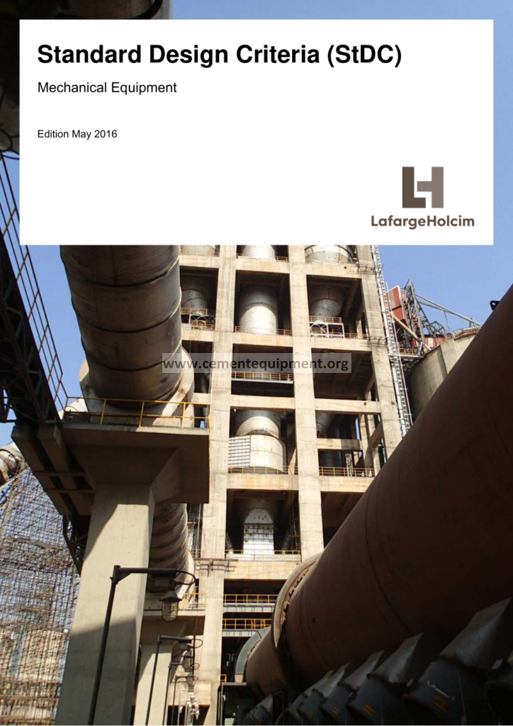
Standard Design Criteria Mechanical: Complete Guide & Downlo
Standard design criteria for mechanical equipment are the engineering backbone of every cement plant project, because they convert project requirements, vendor catalogues and international codes into a single, auditable, repeatable set of rules that mechanical engineers must follow from concept design through to commissioning. Edition M of the standard design criteria for mechanical equipment represents a mature, milestone-based revision of one of the most widely circulated engineering standard documents used inside cement industry engineering departments, and it defines the acceptance thresholds, calculation methods, material grades, safety factors, tolerance limits and documentation requirements that govern rotating equipment, static equipment, drives, gearboxes, couplings and lubrication systems across a modern cement production line. This article expands the content of that standard into a complete technical reference: it explains the purpose and scope of such a standard, the international codes and normative references it relies on, the design basis and service factors used in sizing, the material selection logic for components operating in abrasive and thermal environments, the detailed criteria for rotating equipment, the complete methodology for gearbox sizing and selection, and the full procedure for coupling selection in accordance with internationally recognised standards. Designers, project engineers, graduate mechanical engineers and plant maintenance specialists will find here a practical, clause-by-clause interpretation of the standard together with worked guidance, checklists and selection tables that can be applied directly to real cement plant mechanical design work.
1. Purpose and Scope of the Standard Design Criteria
The purpose of Edition M of the standard design criteria for mechanical equipment is to provide a uniform engineering basis for the mechanical design of all equipment and plant components on a cement production project. Before such a standard existed, each individual vendor, consultant or discipline produced designs that were internally consistent but mutually incompatible, which generated endless interface problems, mismatched spare parts, contradictory foundation drawings and costly site modifications. The standard eliminates this chaos by establishing a single reference for loads, allowable stresses, material grades, surface finishes, tolerances, balancing qualities, lubrication requirements and testing procedures, so that every design, whether performed by the owner, the consultant or a third-party fabricator, is measured against the same yardstick.
The scope of the document typically covers all mechanical equipment groups found on a cement plant, and Edition M specifically addresses the following equipment categories: rotary kilns and kiln drives, raw mills, coal mills and cement mills, bucket elevators, belt conveyors, apron feeders, weigh feeders, air slides, screw conveyors, fans and blowers, compressors, pumps, crushers, grinding media, separators, dust collectors, kiln burners, coolers, preheater internals and all associated gearing, couplings, bearings, lubrication systems and structural supports. It also covers the mechanical design of auxiliary systems such as lubricating oil units, cooling water circuits and compressed air networks where these are part of an equipment supply scope. Equipment not covered, such as electrical machines beyond their mechanical interfaces, instrumentation and civil works, is excluded by an explicit statement of non-applicability, which is important because it defines the boundary between the mechanical discipline and other engineering disciplines.
The standard is written for use at three distinct stages of a project. In the basic engineering stage it defines the design basis and the performance data to be fixed in the equipment specification; in the detail engineering stage it governs the strength calculations, material selection and fabrication details; and in the procurement and manufacturing stage it defines the inspection, testing, painting, packing and documentation requirements that the vendor must comply with. Because the standard is a living document, Edition M is issued as a revision of earlier editions, incorporating lessons learned, new editions of international codes and feedback from construction and commissioning teams. Any deviation from the standard must be requested in writing, justified by sound engineering reasons, and approved by the responsible engineering authority before it can be applied to a purchase order or fabrication drawing.
2. Normative References and International Standards Framework
Edition M builds its technical requirements on a carefully selected set of international, European and German standards that together cover the entire mechanical engineering spectrum relevant to cement plants. The normative references fall into several groups, each addressing a specific technical aspect. For general steel construction and pressure parts the standard cites DIN EN 10025 for structural steels, DIN EN 10028 for pressure vessel plates and DIN EN 10083 for quenched and tempered steels. For welding it references ISO 3834 for quality requirements in fusion welding of metallic materials and DIN EN ISO 5817 for weld defects and acceptance levels, which define the visual acceptance criteria that welds on equipment and structural parts must satisfy.
For shafting and rotating components the standard leans on DIN 743 for the load capacity of shafts and axles, ISO 1940-1 for balance quality requirements of rigid rotors and DIN EN ISO 4288 for surface roughness measurement. For rolling element bearings it adopts ISO 76 for the static load rating, ISO 281 for the dynamic load rating and service life calculation, and ISO 5753 for radial internal clearance. For gears it adopts ISO 6336 for the calculation of load capacity of spur and helical gears, ISO 1328 for gear tooth accuracy tolerances and AGMA 2001 as an alternative accepted calculation method for American-manufactured gear sets. For couplings it references AGMA 9000 and ISO 4878 for flexible couplings together with the coupling manufacturer sizing methods. For belt drives it adopts ISO 4184 for classic and narrow V-belts, and ISO 5293 for conveyor belt design, while for chain drives it uses ISO 606 for short-pitch precision roller chains.
The normative framework also includes standards for fasteners (ISO 4014, ISO 4017, ISO 4032 for hex head bolts and nuts), for lifting and material handling equipment (DIN EN 13155 for load lifting attachments, ISO 4301 for classification of cranes), and for design verification through FEA where required. The list of references in the actual standard document gives the exact edition and year for each code, and the designer is obliged to verify that the latest applicable edition is used at the time of design, because international codes are revised continuously and equipment designed to a superseded edition cannot be justified in a technical audit. Where national or local regulations impose requirements stricter than the cited international codes, the stricter requirement governs, a principle that keeps the standard applicable in all jurisdictions where cement plants are built.
| Standard / Code | Scope in Edition M | Typical Application |
|---|---|---|
| ISO 281 / ISO 76 | Bearing rating life and static load rating | Rolling element bearings for mill, kiln and fan shafts |
| ISO 6336 / AGMA 2001 | Gear tooth load capacity calculation | Gearboxes for mills, kiln drives and conveyors |
| ISO 1940-1 | Balance quality grades of rigid rotors | Fans, rotors, pulleys and mill drive components |
| DIN 743 | Load capacity of shafts and axles | Shaft design for all rotating machinery |
| ISO 4184 | Classic and narrow V-belt dimensions and power ratings | Belt drives for fans, blowers and crushers |
| ISO 606 | Roller chain dimensions and tensile strength | Chain drives for apron feeders and drag conveyors |
| DIN EN 10025 | Hot-rolled structural steel products | Frames, bases, supports and structural steelwork |
| ISO 3834 / ISO 5817 | Welding quality systems and weld acceptance levels | All fabricated equipment and welded structures |
3. Design Basis, Loads and Service Factors
The design basis section of Edition M defines the fundamental assumptions that every mechanical calculation must start from: the design life of the plant, normally twenty to thirty years of operation at full capacity, the ambient temperature range, the operating altitude and its effect on air density and motor power, the dust concentration in the atmosphere and its effect on enclosure ratings, and the site wind, seismic and snow loads that structural supports must resist. The standard also fixes the reference conditions for calculating fan performance, namely a standard air density, because fan power and pressure requirements change with temperature and altitude, and equipment sized for the wrong reference condition will be either oversized and inefficient or undersized and incapable of achieving the guaranteed production rate.
Loads are classified by origin and by duration. Steady-state operating loads arise from process forces such as material weight, grinding forces, chain loads, belt tension and gas pressure differentials; dynamic loads arise from unbalance, misalignment, gear mesh forces, pulsations and the cyclic forces transmitted by crushers and screens; thermal loads arise from temperature gradients, differential expansion and the heat input of clinker, kiln shell and ductwork; and exceptional loads arise from startup, shut-down, emergency braking, jamming, snow, wind and seismic events. Every structural element, bracket, pedestal and machine frame must be designed for the most unfavourable credible combination of these loads, which is why the standard requires each member to be checked for at least the operating case and the exceptional case, with the allowable stress for exceptional cases permitted to be higher because the probability of occurrence is lower.
Service factors, also called application factors, are the standard’s main instrument for turning variable real-world duty into a constant equivalent design load. The service factor for a drive train is the product of the prime mover factor, the driven machine factor and a duty factor that accounts for the number of starts per hour and the running hours per day. For a cement mill main drive, where the driven machine transmits shock loads and runs continuously at high utilisation, the combined service factor may reach 2.0 or higher, while a lightly loaded auxiliary fan drive with a soft-starting motor may require only 1.25. The standard publishes tables of recommended service factors for each combination of driving and driven machine, and it explicitly warns that undersized selection based on nominal power alone is one of the most frequent causes of premature gearbox and coupling failure in cement plants. The design torque for a drive component is therefore the rated motor torque multiplied by the total service factor and, where applicable, by the torque limiting factor of a fluid coupling or torque limiting device fitted upstream.
4. Material Selection Criteria for Mechanical Equipment
Material selection in Edition M follows a structured logic that balances strength, toughness, wear resistance, corrosion resistance, weldability, formability and cost. The standard groups materials by function rather than by catalogue number. Structural steelwork is normally S235JR or S275JR for lightly loaded frames and S355JR where higher strength reduces section sizes and weight; quenched and tempered steels such as S355J2+N are specified for components subject to fatigue, such as kiln shell segments, mill shells and heavy machine frames. For wear components in direct contact with abrasive material, the standard separates the structural function from the wear function: a wear plate is a sacrificial layer of high-chromium white iron or abrasion-resistant steel bolted or welded onto a cheaper structural backing, so that the expensive wear material is limited to the zone where it is actually needed and can be replaced without cutting the structure.
For shafts the standard requires either heat-treatable carbon steels such as C45 (1.0503) or alloy steels such as 42CrMo4 (1.7225), the latter being used where high strength, high toughness and good fatigue resistance are needed at the same time, as in mill trunnions, kiln tyre rings, fan shafts and crusher shafts. The heat treatment is specified together with the mechanical properties: normalized, quenched and tempered, or induction hardened at bearing seats, and the standard requires hardness testing and tensile testing evidence for every delivered shaft above a defined diameter. For gear wheels and pinions, case-hardened alloy steels such as 18CrNiMo7-6 are preferred for high load capacity gear trains because case hardening produces a hard, wear-resistant surface with a tough, shock-resistant core, while for lower duty applications normalized or quenched and tempered steels with surface hardening by induction or flame are accepted.
Selection of bearing materials, seal materials, gasket materials and lubricant compatibility is also governed by the standard. Roller bearings use vacuum-degassed bearing steel with controlled cleanliness; journal bearings use tin-based white metal (Babbitt) bonded to steel or bronze shells; seals are selected according to the sliding speed, the shaft diameter and the contamination level of the environment; and the standard requires that all non-metallic materials in contact with lubricants, such as elastomer seals and coupling elements, be compatible with the specified oil or grease type and temperature range. Corrosion protection is a material requirement in its own right: carbon steel components that operate in humid or wet areas, such as cooling tower basins, slurry lines and outdoor structures, are either coated with corrosion protection systems specified in the painting standard or upgraded to stainless steel where coatings cannot be maintained, and the standard fixes the minimum surface preparation grade and coating thickness for each service environment.
5. Design Criteria for Rotating Equipment
Rotating equipment design in Edition M is governed by a comprehensive set of criteria covering shaft strength, deflection, critical speed, balance quality, bearing selection and dynamic behaviour. Shaft design begins with the combined bending and torsion calculation, using the equivalent stress method, in which the maximum bending moment from the applied loads and the design torque from the drive train are combined into a von Mises equivalent stress that must not exceed the allowable stress for the shaft material with the required safety factor. For shafts in fatigue service the standard additionally applies a fatigue analysis with stress concentration factors at shoulders, keyways, splines and interference fits, because these features, and not the plain shaft body, are the usual location of fatigue failures.
Shaft deflection and slope at bearing positions are limited to protect the bearings and the dynamic behaviour of the rotor. The standard typically limits the slope at the bearing seats to values compatible with the internal clearance and the load distribution capability of the selected bearing, commonly in the order of 0.001 to 0.002 rad for rolling element bearings, and limits the total shaft deflection at seals, impellers or gear seats to values that prevent interference and uneven load sharing. Where these limits cannot be met with a reasonable shaft diameter, the standard requires a redesign of the bearing arrangement, a stiffening of the shaft, or the acceptance of an increased bearing size, rather than the acceptance of an over-deflected shaft.
Critical speed calculation is mandatory for all high-speed rotating equipment. The standard requires the lateral critical speeds of the rotor-bearing system to be separated from the operating speed range by a margin, commonly at least 15 to 20 percent, and requires that any critical speed inside the operating range be crossed quickly and be verified by a run-up test after installation. Balance quality is specified in accordance with ISO 1940-1, with balance quality grades chosen according to the type and speed of the machine: rigidly mounted fans and pump impellers typically require balance quality grade G6.3 at lower speeds, while higher speed rotors such as separator cages, mill classifiers and turbo blowers are balanced to G2.5 or G1.6, and the standard fixes the balance test procedure, the balancing planes and the residual unbalance acceptance limits. Vibration acceptance is then verified on site against ISO 10816 zone limits for the machine category, and the standard requires runout limits for shafts, coupling hubs and flanges to be stated on the drawing.
6. Gearbox Sizing and Selection per International Standards
Gearbox selection is one of the most consequential mechanical decisions on a cement plant, because the main drives for mills, kilns, crushers and conveyors are among the most expensive, most heavily loaded and most difficult to replace components on the site. Edition M requires gearboxes to be selected on the basis of the equivalent torque calculated from the rated motor power, the selected service factor and the gearbox ratio, and it explicitly requires the thermal rating of the gearbox to be checked in addition to the mechanical rating, because a gearbox that is mechanically sufficient but thermally insufficient will overheat, degrade its oil and fail prematurely in continuous high-temperature service such as a kiln drive in a hot climate.
The tooth load capacity calculation is performed in accordance with ISO 6336 for spur and helical gears, which gives the allowable contact (pitting) stress and the allowable bending stress at the tooth root, and in accordance with AGMA 2001 as an equivalent accepted method for gears manufactured to American practice. The calculation considers the applied torque, the gear geometry, the material and heat treatment, the accuracy grade, the number of cycles over the design life, the lubrication regime and the application factor, and the result is expressed as a calculated safety factor against pitting and a calculated safety factor against tooth breakage, both of which must exceed the minimum values specified by the standard. For bevel and worm gears, the corresponding international calculation methods are applied, and for the very large girth gears used on rotary kilns and ball mills, the standard applies the dedicated calculation procedure for open gear drives with their specific geometry, including the pinion, the girth gear and the case, because the design rules for enclosed gear units do not directly transfer to large open gear sets.
Beyond strength, the standard governs the accuracy grade of the gearing, the backlash, the contact pattern and the heat treatment of the teeth. Gear accuracy is specified in accordance with ISO 1328, with accuracy grades selected according to the peripheral speed and duty: precision ground gearing for high-speed drives, hobbed or shaped gearing of moderate accuracy for mill and kiln drives, and the standard requires the pinion and gear wheel of every gearbox to be matched and lapped together where necessary to achieve the required contact pattern. The design of the gearbox housing, the bearing selection for the gear shafts, the sealing arrangement at the shafts, the oil supply and filtration system, and the instrumentation for oil temperature, oil pressure and bearing temperature are all specified in the standard, together with the requirement for a nameplate, a data sheet, a dimension drawing and a full calculation report to be delivered with every gearbox. Finally the standard requires the gearbox manufacturer to demonstrate that the unit has been factory tested, either by a no-load running test, a full-load test on the test rig where contractually agreed, or at least a partial-load run, with vibration, temperature and noise measurements recorded in a test certificate.
7. Coupling Selection per International Standards
Coupling selection in Edition M is a systematic procedure that starts from the function the coupling must perform: transmitting torque, compensating for radial, axial and angular misalignment, protecting the drive from shock loads, or providing torque limiting. The standard classifies couplings into rigid couplings, which are used only where the shafts are precisely aligned and there is no relative movement between them, and flexible couplings, which are used everywhere else. Among flexible couplings the standard distinguishes elastomeric couplings, which use rubber or polyurethane elements for vibration damping and are used for light and medium duty drives, metallic couplings such as gear couplings and grid couplings, which are used for heavy duty drives where high torque and significant misalignment must be accommodated, and special couplings such as fluid couplings, which provide soft start and torque limiting for high-inertia drives such as ball mills, and torsionally soft couplings for reciprocating machinery.
The sizing calculation for a flexible coupling follows the same logic as gearbox selection: the coupling nominal torque rating must exceed the design torque, which is the rated motor torque multiplied by the service factor appropriate for the drive category. Coupling catalogues publish a torque rating for each size, and the standard requires the applied service factor to be chosen from a table that distinguishes between uniform loads, moderate shock loads and heavy shock loads, between continuous duty and frequent starts, and between rigidly mounted and resiliently mounted machines. Because couplings must also accommodate the expected misalignment, the standard requires the coupling to be selected with misalignment capacities exceeding the installation and operating misalignment values, and for gear couplings it requires that the teeth be correctly lubricated and that the coupling have adequate axial float for the thermal expansion of the connected shafts, a point that is frequently missed on kiln drives where the kiln shell grows significantly with temperature.
For kiln drive and mill drive couplings, Edition M commonly specifies gear couplings with continuous lubrication or grease-packed grids, or, on modern plants, dry couplings with engineered torque transmission elements that require no lubrication. The standard requires the coupling to be dynamically balanced to the balance quality grade of the rotating assembly, because a heavy unbalanced coupling will dominate the vibration signature of the drive train, and it requires the coupling hub bores to be machined to the correct fit and keyway tolerances for the shaft. The alignment tolerances for the connected shafts are specified in the standard in terms of parallel offset and angularity, and the standard requires alignment to be performed by the reverse indicator or laser alignment method with the thermal growth compensation taken into account, and the final alignment values to be recorded and retained in the commissioning documentation. On the subject of safety, the standard requires all couplings above a defined peripheral speed to be fitted with guards, and all high-speed couplings to be fitted with an enclosing guard that contains any element that could be thrown out in the event of failure.
8. Belt and Chain Drives Design Criteria
V-belt and roller chain drives remain common on cement plants for auxiliary equipment such as crushers, fans, blowers, weigh feeders and some elevators, and Edition M provides explicit design criteria for them. V-belt drives are designed in accordance with ISO 4184, which covers the belt cross sections, the effective lengths and the power ratings of classic and narrow V-belts. The design procedure fixes the service factor for the application, converts the motor power into the required belt power rating, selects the belt section, calculates the pulley diameters and the belt speed, which should normally be kept below the manufacturer’s recommended maximum to avoid heat generation and short belt life, computes the number of belts from the transmitted power per belt, and checks the centre distance and the arc of contact correction factor, because power capacity drops rapidly when the arc of contact on the small pulley falls below the optimum.
The standard additionally requires that belt drives be fitted with an adjustable or spring-loaded tensioning device, that pulley alignment be held within the stated tolerance, and that belt guards be fitted for safety. For high horsepower applications, and especially where shock loads are present, the standard warns that a V-belt drive may require an unusually large number of belts, and directs the designer to consider either a narrower belt section, a toothed belt, or a direct gear drive instead. Chain drives are designed in accordance with ISO 606, with the chain size selected on the basis of the transmitted power and the required speed ratio, the sprocket tooth count chosen to give smooth operation and acceptable chain speed, and the chain length and centre distance calculated to avoid resonance and to allow for chain wear elongation over the life of the drive. Lubrication requirements are specified according to chain speed, from manual lubrication at low speeds to oil bath and force-feed lubrication at high speeds, and the standard requires proper chain tensioning and regular monitoring of chain elongation, which is the main wear mechanism limiting chain life.
9. Bearings, Seals and Lubrication Systems
Bearing selection in Edition M starts from the load, the speed, the bearing arrangement and the required life, and proceeds through the ISO 281 dynamic rating calculation, which yields a calculated basic rating life in operating hours that must equal or exceed the standard’s minimum design life for the equipment class, commonly 50,000 hours for main drives and proportionally less for intermittently operated auxiliary equipment. Where the bearing arrangement uses two bearings on a shaft, the standard requires the designer to fix the axial locating arrangement: one bearing carries the axial load and locates the shaft, while the other bearing allows axial expansion to accommodate thermal growth, a requirement that is absolutely critical on kiln support rollers, mill trunnions and long conveyor head shafts where differential expansion would otherwise overload the bearings. The static load rating check is performed in accordance with ISO 76, especially where bearings are subjected to momentary overloads, shock loads or slow rotation under heavy load, and the standard requires the minimum load on each bearing to be checked, because lightly loaded rolling bearings skid and fail prematurely.
Sealing is specified according to the duty and the contamination level. The standard distinguishes between contact seals, such as radial lip seals, which are used where cleanliness is high and speeds are moderate, non-contact seals, such as labyrinth seals, which are used in dirty environments and at higher speeds where a lip seal would wear rapidly, and combined sealing arrangements, which use a non-contact outer seal to shed dust and a contact inner seal to retain the lubricant. For mill and kiln trunnion seals, which operate in the most aggressive dust and temperature environment on the plant, the standard specifies multi-stage sealing with purge air or grease injection to keep dust out of the bearing housing. Lubrication systems are specified in full: circulating oil systems for large gearboxes and kiln drives, with oil pumps, filters, coolers, pressure and temperature instrumentation and interlocks; grease systems for open gears, chains and bearings that are difficult to reach; and automatic lubrication for long conveyor idler bearings and bucket elevator chains. The standard fixes the oil grades by viscosity class, the cleanliness level by ISO 4406 particle counts, and the requirement that every lubrication point be identified, tagged and documented on the lubrication chart, because a lubrication system that is not documented cannot be operated or maintained reliably.
10. Structural Supports, Foundations and Machine Frames
The mechanical design of equipment does not stop at the machine boundary, because the behaviour of rotating equipment is only as good as the structure that supports it. Edition M therefore specifies design criteria for machine frames, pedestals, and the structural steelwork of support platforms, and interfaces with the civil discipline on foundations. Machine frames and pedestals must be rigid enough that their natural frequency does not coincide with the operating frequency of the mounted machinery, and the standard requires either a stiffness calculation or a modal analysis to demonstrate separation, with tuning by increased stiffness, increased mass or changed support location where a resonance is found. The base plates of rotating equipment must be machined flat within the specified tolerance, grouted after alignment, and fitted with levelling and adjusting elements for final alignment.
For heavy rotating equipment such as mills, kilns and crushers, the standard requires the equipment and its foundation to be treated as a coupled dynamic system, and specifies that foundation design be based on the dynamic loads transmitted by the machine, not merely the static weight. The dynamic loading includes unbalance forces, which increase with the square of the speed, the cyclic forces from gear mesh and crusher impact, and, for reciprocating machines, the inertia forces from the moving masses. The standard sets limits on foundation vibration amplitudes at the machine mounting points, requires the soil and pile characteristics to be verified, and requires the foundation natural frequency to be separated from the machine operating frequency and its harmonics. The interface between the mechanical and civil disciplines is fixed by a requirement that all reaction forces and moments, all equipment weights, all erection loads and all dynamic load data be supplied to the civil designer as part of the equipment data sheet, so that the foundation is designed to the same loading envelope as the machine itself.
11. Fabrication, Welding and Dimensional Tolerances
Edition M devotes a substantial section to fabrication and welding because the majority of mechanical equipment on a cement plant, from kiln shell segments to mill shells, from cyclone cones to conveyor frames, is welded fabrication rather than machined product. The standard requires all welding to be performed by welders and welding operators qualified in accordance with ISO 9606, all welding procedures to be qualified in accordance with ISO 15614, and the quality management of the fabrication to be in accordance with ISO 3834 at the quality level appropriate to the component. Welds are classified by their structural significance: full penetration butt welds on kiln shells, mill shells, pressure parts and critical flanges are subject to the highest quality level and to non-destructive examination, while fillet welds on secondary brackets and supports are subject to visual inspection and lower acceptance levels. The standard fixes the weld inspection programme in terms of the percentage of welds examined by visual testing, magnetic particle testing, ultrasonic testing and, where applicable, radiographic testing, with the percentages rising for the most critical welds.
Dimensional tolerances are specified for each equipment class and are expressed on the fabrication drawings. For rotating assemblies the standard specifies the runout of machined surfaces, the parallelism and squareness of flanges, and the concentricity of bores; for structural fabrication it specifies the overall length, width, height and flatness tolerances and the squareness of frames; and for assembly it specifies the alignment tolerances between connected components. The standard also addresses the fabrication sequence for large shells, requiring trial assembly, tack welding, full welding with controlled heat input, and dimensional verification before and after welding, because distortion from welding is one of the most common causes of out-of-tolerance shells. Stress relieving by post-weld heat treatment is required where the combination of plate thickness, weld type and service stress makes it necessary, and the standard specifies the heat treatment temperature, the holding time and the cooling rate.
12. Painting, Preservation, Packing and Shipping
The protection of equipment between fabrication and operation is handled by the painting, preservation and packing requirements of Edition M. The painting system is selected by service environment: an outdoor atmosphere in a tropical or marine location demands a more substantial coating system, including zinc-rich primer, intermediate coat and a high-build top coat, than an indoor, dry environment. The standard fixes the surface preparation grade, normally Sa 2.5 (near-white metal) for the primary coat, the minimum and maximum dry film thicknesses for each coat, the curing conditions and the repair procedure for damaged coating. Colour coding of the final coat follows a plant standard so that gas ducts, water lines, oil lines, compressed air lines and fire-fighting systems can be identified visually at a glance.
Preservation is specified for the period between manufacture and installation, which can last many months on a cement project. Machined surfaces are coated with a removable rust preventive; bearings, gearboxes and lubrication systems are either filled with the correct oil for storage or protected with vapour phase inhibitors; open gear faces and coupling teeth are greased; and equipment shipped in crates is protected against moisture with desiccants and sealed vapour barriers where required. The packing specification fixes the crate construction, the weight and dimension limits for road, sea and air transport, the lashing and lifting points, the marking of crates with project and equipment identification, and the requirement for a packing list in each crate. On arrival, the standard requires the receiving inspection to check for damage, to verify the packing list against the delivery, and to record any deviations before the equipment is accepted, because claims for transportation damage cannot be sustained after acceptance of the equipment.
13. Engineering Documentation and Deliverables
A standard that governs the design but does not govern the documentation would be ineffective, because the documentation is what makes the design auditable, maintainable and operable. Edition M therefore defines the complete documentation set that must be delivered with every equipment item. The minimum mechanical documentation includes the equipment data sheet, which fixes the duty point, the operating conditions and the design requirements in a single reference document; the general arrangement drawing, showing the equipment, its connections, its clearances and its interfaces; the foundation and anchor bolt drawings; the detailed fabrication drawings of the components; the calculation report for strength, gearbox, coupling, bearing and critical speed calculations; the assembly and installation instructions; the operating and maintenance manuals; and the lubrication chart and spare part list. Each drawing must show the design standard applied, the material grades, the surface treatments, the tolerances and the inspection requirements, so that the drawing is a complete manufacturing and inspection specification in itself.
The standard also defines the documentation workflow: preliminary documents are submitted for review and comment, comments are resolved, approved documents are issued for construction or manufacture, and as-built documentation is issued at the end of the project reflecting the actual delivered configuration. The revision control system is specified so that every document carries a unique number, a revision letter, an issue status and a revision note, and so that superseded revisions are removed from circulation. Edition M requires this documentation discipline to extend to vendor documentation, which must comply with the same numbering, revision and approval rules, and to the commissioning documentation, which must record the alignment values, the test results, the vibration readings and the functional test records that prove the equipment was handed over in a condition consistent with its design. For the plant operator, this documentation set is the foundation of the maintenance system, the spare parts management system and the statutory inspection regime, which is why the standard treats documentation not as an administrative burden but as a deliverable of equal importance to the equipment itself.
14. Inspection, Testing and Quality Assurance
Edition M requires each equipment item to pass a defined inspection and testing programme at the manufacturer’s works before shipment, complemented by site inspection and testing after installation. The works inspection covers dimensional inspection against the fabrication drawings, material verification by checking material certificates and, where specified, chemical and mechanical testing, weld inspection by visual and non-destructive examination, hydrostatic testing of pressure parts and tanks, balance testing of rotating assemblies, and a running test of the complete machine where this is feasible. The running test measures vibration in accordance with ISO 10816, bearing temperatures, oil temperatures and pressures, noise levels, and the absence of abnormal leakages, and the results are recorded in a test certificate that is reviewed and approved before release for shipment.
The inspection and testing plan is a contractual document that fixes, for each equipment item, the inspection points that are mandatory hold points, at which the buyer’s inspector must witness the inspection or the work cannot proceed, and the inspection points that are witness points, at which the buyer is informed and may attend. The standard requires the manufacturer to issue the inspection records, test certificates, material certificates and calibration certificates that support the inspections, and requires that all inspection and testing equipment used be calibrated with certificates traceable to national standards. On site, the standard requires installation to be inspected and tested in a similar systematic way: alignment verification, bolt torque verification, lubrication system flushing and verification, electrical and mechanical interlock testing, no-load running, and finally load running and performance testing. The quality assurance philosophy of the standard is that verification at each step prevents failures at the next step, and that every acceptance must be documented, because an undocumented acceptance is, in the terms of the standard, no acceptance at all.
15. Deviation Control and Quality Management System
No matter how comprehensive a standard is, real projects will always generate situations in which the standard cannot be applied directly, and Edition M provides the mechanism for handling such deviations. A deviation request is raised in writing, stating the clause of the standard that cannot be met, the reason why, and the proposed alternative with its engineering justification. The deviation is reviewed for its impact on safety, on strength, on reliability, on maintainability and on cost, and is approved only where the alternative achieves an equivalent level of technical assurance. Approved deviations are recorded in a deviation register that is reviewed at project milestones, so that recurring deviations can be identified and fed back into the next edition of the standard. This closed loop between project experience and standard revision is precisely how Edition M itself evolved from earlier editions, and it is the reason why a mature standard document is not a static rulebook but a living engineering system.
The quality management framework of Edition M aligns with ISO 9001 principles applied to design and procurement. Every design is verified independently by a second engineer or, for critical components, by an independent calculation check. Every drawing and calculation is reviewed against the applicable standard clauses, and the review is documented on the document control system. The standard requires the design organisation to maintain qualified staff, controlled design software with validated calculation procedures, and a non-conformance and corrective action system that captures failures and design errors and converts them into improved procedures. It is this combination of technical criteria and management requirements that makes Edition M a genuinely complete engineering standard, rather than a collection of numbers, and that gives the equipment designed under it the demonstrated reliability that cement plant operators expect over a thirty-year design life.
16. Frequently Asked Questions
What is Edition M of the Standard Design Criteria for Mechanical Equipment?
Edition M is the May 2016 revision of an engineering standard document used in the cement industry that defines the design basis, loads, material grades, calculation methods, tolerances and documentation requirements for all mechanical equipment on a cement plant, from kilns and mills to fans, conveyors and gearboxes.
Which international standards does the document rely on for gearbox sizing?
Gearbox sizing is performed in accordance with ISO 6336 for spur and helical gears, with AGMA 2001 accepted as an equivalent method for American-manufactured gearing, and the standard additionally requires the thermal rating of the gearbox to be checked in addition to its mechanical rating.
How is coupling size determined?
The coupling is sized so that its rated torque exceeds the design torque, which is the rated motor torque multiplied by the service factor for the drive category, and it is additionally verified for misalignment capacity, axial float for thermal growth, dynamic balance and, for kiln and mill drives, lubrication requirements.
Why are service factors so important in cement plant drive design?
Service factors convert the real, fluctuating duty of the driven machine into an equivalent design load, and undersizing a gearbox or coupling on nominal power alone is one of the most frequent causes of premature failure of cement plant drive trains.
What balance quality grades are required for rotating equipment?
Balance quality grades are selected in accordance with ISO 1940-1 according to machine type and speed, with G6.3 typical for lower-speed fans and pumps and G2.5 or G1.6 required for higher-speed rotors such as separator cages and turbo blowers.
17. Summary
Edition M of the Standard Design Criteria for Mechanical Equipment provides the complete, auditable engineering framework that governs the mechanical design of cement plant equipment, from the definition of the design basis and service factors to the selection of materials, the calculation of shafts and bearings, the sizing of gearboxes and couplings, and the specification of fabrication, inspection, painting, documentation and quality assurance requirements. Its power lies in the fact that every design decision is anchored to a named international standard, every calculation has a defined method and an acceptance criterion, and every deliverable has a defined documentation format, which makes the design process repeatable, reviewable and improvable across projects. For the practising engineer the standard is both a design manual and a quality system: it tells you what to calculate, how to calculate it, what values are acceptable, and how to prove that you did it correctly. For the plant owner it is the instrument that turns the ambition of a thirty-year reliable plant into a contractually enforceable engineering requirement. This article has interpreted the main clauses of the standard in practical terms, covering rotating equipment design, material selection, gearbox sizing, coupling selection and the surrounding engineering disciplines, and it provides the checklist, table and procedural framework needed to apply the standard to real cement plant design work. Designers who internalise this framework design equipment that survives; those who ignore it inherit the consequences of failure. As the closing statement of the original document reminds every user, the standard is only as effective as the discipline with which it is applied, and the discipline begins with reading the clauses before designing, not after the failure has occurred.
Get this cement file + the full 931-file package
$249 — one-time purchase, instant download, lifetime access
This file is part of the Complete Cement Technical Package (931 files) available from cementequipment.org. Respective rights holders; library copy for the licensed single user.