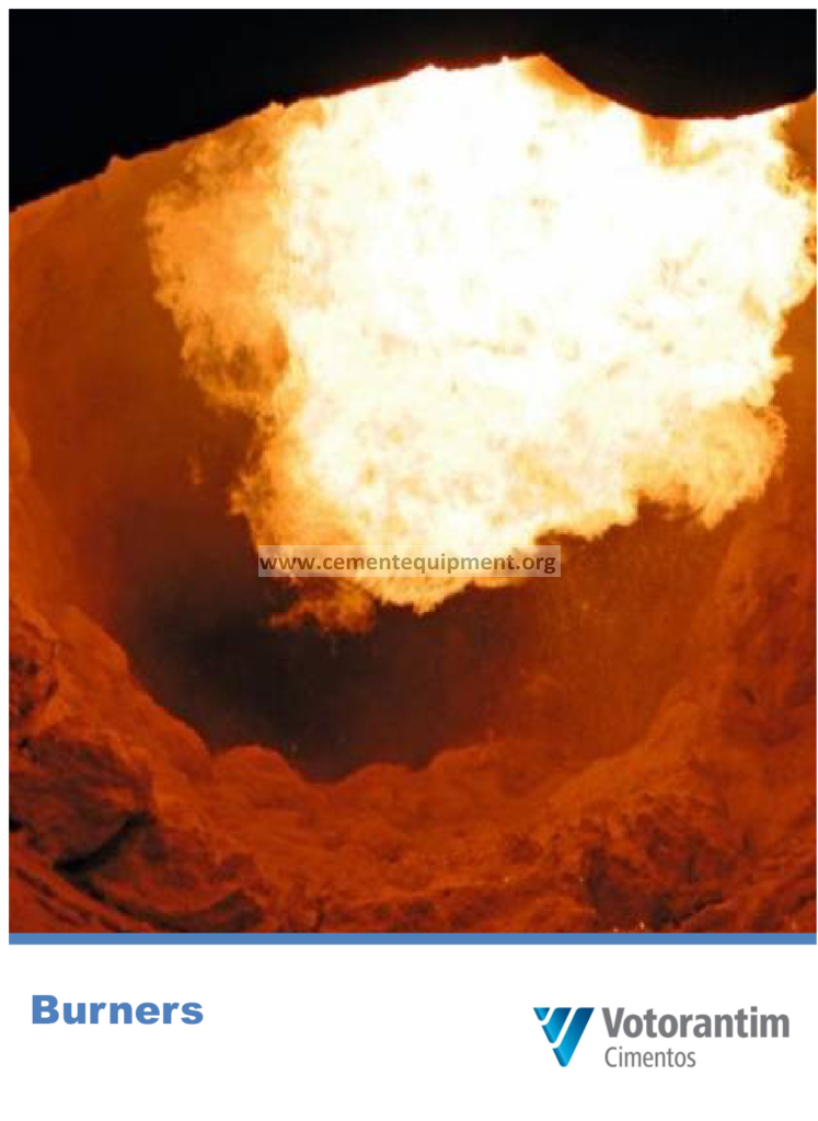
Kiln Burners: Design, Flame Control & Tuning Guide
The kiln burner is the flame that makes the clinker: it is the highest-temperature point in the cement plant, the instrument that shapes the burning zone, and one of the most under-appreciated pieces of equipment in the pyroprocessing line. A well-adjusted burner delivers a short, stable, slightly luminous flame that concentrates heat in the burning zone, builds a healthy coating, fires the alternative fuels and produces the lowest possible NOx; a misadjusted burner produces a long, lazy flame that overheats the feed end, destroys the coating, shortens refractory life and costs the plant millions in fuel, quality and availability. This article is a complete technical reference on burners for rotary kilns. It covers the burner’s place in the kiln system, the design of multi-channel burners, the physics of the flame, momentum and swirl, fuel preparation and delivery, alternative fuel firing through the burner, operation and adjustment, common problems, and the safety and maintenance regimes that keep the flame under control.
1. The Burner in the Kiln System
The rotary kiln is fired from the discharge end: the burner pipe projects through the kiln hood into the kiln, the flame develops along the kiln axis, and the combustion air enters from two sources. Primary air is delivered through the burner itself with the fuel, normally 8 to 15 percent of the stoichiometric air; secondary air is the hot combustion air from the clinker cooler, drawn into the kiln through the hood at 700 to 1,000 degrees Celsius, and it provides the bulk of the oxygen. The ratio between the two, and the momentum with which the primary air leaves the nozzle, decides the flame shape, the flame temperature and the stability of the burning zone.
The burner has three distinct jobs. The first is combustion: to mix fuel and air fast enough that the fuel burns completely within the kiln, leaving no unburned char to contaminate the clinker or elevate the kiln inlet temperature. The second is flame shaping: to produce a flame of the length and shape that deposits its heat on the clinker bed at the right axial position, with a peak flame temperature high enough to drive clinkering at 1,400 to 1,450 degrees Celsius in the material. The third is protection: to keep the flame clear of the refractory lining and the material, protecting the coating and the shell. Every design feature and every operating adjustment of the burner serves one of these three jobs.
2. Flame Physics: Temperature, Length and Luminosity
The flame in a rotary kiln is a turbulent diffusion flame: fuel and air mix by turbulence, the reaction zone is distributed over the flame volume, and the flame length is set by the mixing rate rather than by chemical kinetics. The adiabatic flame temperature of coal-air combustion is about 2,000 to 2,200 degrees Celsius, but the practical flame temperature in the kiln is 1,600 to 1,900 degrees Celsius because of radiation losses and excess air, and the measured gas temperature in the burning zone sits in the 1,400 to 1,600 range. The flame temperature decides the heat transfer rate: radiation from the flame and the hot gas dominates, transferring 60 to 70 percent of the heat to the material and the lining.
Flame length is the central operating variable. A short flame releases all its energy in a few meters and produces a hot, narrow burning zone with strong radiation; a long flame spreads the energy release along 20 meters and produces a gentle, wide temperature profile. The operator chooses between them with the momentum and the swirl of the burner: high axial momentum stretches the flame, high swirl shortens and widens it. The luminosity of the flame matters for heat transfer: a luminous flame radiates like a black body because of the soot particles formed in fuel-rich zones, and its heat transfer coefficient is two to three times that of a non-luminous flame, which is why the flame is adjusted to be slightly luminous rather than blue.
The burner’s own design defines the envelope within which the operator works: the axial velocity range of 100 to 250 meters per second, the swirl velocity range, the number and position of the fuel channels, and the ratio of axial to swirl momentum, expressed as the dimensionless momentum parameter typically held between 1.5 and 3. The physical result is a recirculation zone immediately in front of the nozzle that stabilizes the flame and pulls hot combustion products back to the fuel jet, anchoring the flame at a fixed distance from the tip.
3. From Single-Channel to Multi-Channel Burners
The historical burner was a single pipe carrying the fuel, with primary air blowing around it: a simple device whose flame could barely be adjusted and whose primary air consumption of 25 to 35 percent was a severe penalty, because every kilogram of cold primary air displaced hot secondary air and raised the specific heat consumption by 2 to 5 percent. The modern multi-channel burner uses a fraction of the primary air — 8 to 12 percent for coal and down to 6 to 8 percent with oxygen enrichment — and shapes the flame with two or more air streams of different velocity and swirl. The channels, from the center outward, are typically the central fuel lance, the main fuel annulus, an axial air channel, a swirl air channel and an outer alternative-fuel channel, with individual flow control on each.
The performance gains of the multi-channel design are well documented. Primary air is reduced by more than half, saving 15 to 40 kJ per kilogram of clinker in heat consumption. The flame becomes adjustable online, allowing the operator to respond to coating state and clinker quality within minutes. The NOx emission falls by 20 to 40 percent because the intense mixing and staged flame geometry reduce peak flame temperature. And the burner can carry the alternative fuels, because its annular channels can be sized for the coarse, irregular particles of solid recovered fuel and the high gas flow of petcoke without upsetting the main flame. The cost is complexity: each channel needs its own flow metering, control valve and interlock, and the burner maintenance requires the same care as the kiln itself.
4. Momentum, Swirl and the Flame Shape
The two numbers that describe the aerodynamic design of a burner are the momentum and the swirl. Momentum is the product of the mass flow and the velocity of each air stream; the axial momentum of the burner is the sum over the channels, and the flame length scales with the axial momentum density — the momentum per unit area of the nozzle. A burner designed for 15 kilograms per meter second squared of axial momentum with a 100-millimeter nozzle produces a markedly different flame from one with the same momentum and a 150-millimeter nozzle. The design values are set by the kiln diameter, the fuel type and the target flame length: a 4.8-meter kiln firing coal with a 15-meter flame needs an axial momentum density in the 12 to 18 kilogram per meter second squared range.
Swirl is the tangential component of the air velocity, produced by guide vanes or tangential slots in the swirl channel. The swirl number, the ratio of tangential to axial momentum flux, decides the radial expansion of the flame: at a swirl number below about 0.6 the jet remains essentially axial, between 0.6 and 1.2 the flame widens progressively, and above 1.2 the recirculation becomes so strong that the flame attaches to the nozzle with intense back-mixing. The practical setting keeps the swirl moderate: strong enough to spread the flame and mix the secondary air, weak enough that the flame does not wash the refractory or drag the coating. The operator’s adjustment — axial flow up and swirl down to lengthen the flame, the reverse to shorten it — is the most frequent flame control action in daily operation.
5. Fuel Preparation and Delivery to the Burner
The burner is the last element of the fuel system, and its performance depends on everything upstream. For coal, the preparation is grinding in the coal mill to a fineness of 1 to 3 percent residue on 90 micrometers, with the moisture reduced to below 1.5 percent; the delivery is pneumatic conveying in the coal injection line at a velocity of 20 to 30 meters per second, with the air-to-coal ratio and the line pressure drop monitored as the standard indicators. For petcoke, the fineness is 1 to 2 percent residue on 90 micrometers with a moisture below 2 percent, and the ignition is helped by a slightly higher primary air temperature or the addition of a small amount of more reactive fuel. For alternative fuels, the preparation is a size reduction to below 30 to 50 millimeters for solid recovered fuel, with the oversize fraction returned, and the delivery is through a separate channel with a conveying velocity high enough — above 25 meters per second — to keep the coarse particles suspended.
The fuel quality variables that the burner operator watches are the net calorific value, the moisture, the ash content and the particle size. A drop in calorific value requires more fuel mass flow, which changes the momentum balance and the flame; a rise in moisture delays ignition and lengthens the flame; a rise in ash raises the ash deposition on the coating; and coarse particles fall through the flame into the bed, burning late and creating local reducing conditions. The modern plant feeds this data to the kiln control system, which compensates the burner settings continuously.
6. Alternative Fuels Through the Main Burner
The main burner is the second firing point for alternative fuels, after the calciner, and its role is different: the kiln flame must remain hot and stable, so the alternative fuel share at the main burner is limited to 20 to 40 percent in normal operation. The fuels fired through the main burner are the ones with adequate heating value and grindability or size: shredded tyres cut to below 50 millimeters, solid recovered fuel with a calorific value above 16 to 18 MJ per kilogram, bone meal and dried sewage sludge with a calorific value of 8 to 14 MJ per kilogram, and liquid solvents injected through the central lance. The burner design accommodates the fuel with a dedicated channel whose cross-section is sized for the volumetric flow, and with wear protection at the nozzle, because the coarse, abrasive particles erode the tip quickly.
The operating challenges of main-burner alternative fuels are burnout, momentum and quality stability. Burnout must be checked with CO and O2 analysis at the kiln inlet: a CO spike above 0.5 percent means incomplete combustion, risking build-up in the preheater and a kiln reducing atmosphere. The fuel mass flow changes the total momentum of the jet, so the air settings must be rebalanced when the alternative fuel rate changes. And the quality of the alternative fuel varies by delivery, so the plant runs a blend or a stabilizing buffer to keep the flame conditions constant. The documented operating envelope is a main-burner substitution of 30 to 40 percent with solid recovered fuel of good quality, and 50 percent or more where the plant has a carefully controlled multi-fuel strategy and the kiln operation is stable.
7. Ignition, Start-Up and Pilot Burners
Starting the kiln flame is a procedure with its own equipment and its own rules. The ignition sequence begins with the pilot: a small gas or oil burner, or an electric igniter, inside the main burner that provides the ignition source. The main fuel flow is then opened in steps, with the primary air set for maximum stability, and the flame is confirmed by the flame detector and the operator’s sight glass before the feed and the kiln speed are raised. The rules of the sequence exist because a flame failure at the wrong moment means an explosion hazard: unburned fuel accumulating in the kiln and the preheater can detonate when the ignition is restored, which is why the purge procedure — sweeping the kiln with air for a defined period to remove accumulated fuel gas — precedes every ignition attempt.
The flame detector is a safety-critical instrument: a UV or infrared sensor in the burner that trips the fuel valves within seconds if the flame is lost. The detector must be kept clean, correctly aligned and tested, because its failure mode is the explosion: a detector that does not see the flame leaves the fuel open into a cold kiln. The ignition gas system — the gas train with its pressure switches, shut-off valves and leak tests — is inspected on the schedule defined by the fuel code and the plant’s own audit findings.
8. Burner Adjustment and the Operating Envelope
The adjustment of the burner is a set of coordinated movements: axial air, swirl air, total primary air, fuel rate and, in modern burners, the alternative fuel channel. The adjustment procedure is a structured experiment, not an art: the operator defines the objective — shorter flame, higher peak temperature, less NOx, more alternative fuel — moves one channel at a time by a defined step, waits for the kiln to respond over 30 to 60 minutes, and records the effect on flame shape, burning zone temperature, kiln inlet temperature, NOx, free lime and coating state. The result is a documented operating envelope: the matrix of settings for the normal fuels, the alternative fuel blends and the seasonal clinker qualities, maintained in the control room as the reference.
The daily tuning is the fine control: small movements of axial and swirl air to compensate for coal quality, ambient temperature and cooler operation. The weekly tuning is the review: the process engineer compares the week’s flame settings, the coating history and the refractory thermography, and decides whether the envelope itself needs revision. The benchmark of a well-tuned burner is a stable burning zone temperature with a peak-to-average spread of under 50 degrees, a free lime at the target with low variability, an inlet temperature on the design curve, and a coating profile that protects the burning zone bricks over the full campaign.
9. Common Burner Problems and Their Diagnosis
The characteristic problems of kiln burners are each linked to a cause. A flame that is too long deposits its heat beyond the burning zone, raises the kiln inlet temperature and the NOx, and is cured by increasing the swirl or reducing the axial air. A flame that is too short and hot washes the lower transition zone, stripping the coating and exposing the brick; the cure is the opposite adjustment. A flickering or unstable flame points to coal quality variation, a partially blocked fuel nozzle or a worn swirl vane, and the diagnosis starts with the fuel system data before the burner internals. A flame that sits off-center, washing one side of the kiln, points to a misaligned burner pipe, and the correction is the alignment procedure, not the air settings. A rising CO with a normal flame points to incomplete burnout of coarse fuel particles, and the correction is fuel sizing. Each problem has a signature in the data — the kiln inlet temperature, the NOx, the shell scanner profile and the free lime — and the disciplined diagnosis reads the signature before touching the burner.
10. NOx Formation and the Burner’s Role
The burner is the first line of defense against NOx, and its contribution is now a design criterion. NOx forms by three routes in the kiln flame: thermal NOx from the oxidation of nitrogen at flame temperatures above 1,500 degrees Celsius, prompt NOx from hydrocarbon radicals in the flame front, and fuel NOx from the nitrogen bound in the coal. The burner design attacks all three: the flame is aerodynamically staged so that the fuel-rich core consumes the oxygen at moderate temperature; the mixing is tuned so that the peak flame temperature is suppressed; and the momentum is balanced so that the flame does not entrain extra air into the hottest zone. The measurable result is a burner that produces 20 to 40 percent less NOx than a conventional flame at the same conditions, which reduces the SNCR reagent consumption proportionally.
The operator’s NOx tools within the burner are the flame staging and the momentum balance, and the kiln’s overall NOx management adds the calciner temperature control, the oxygen level and the kiln feed stability. The interaction is why the burner adjustment and the kiln control strategy are reviewed together: a burner tuned for minimum NOx alone may lengthen the flame enough to cost 10 degrees of burning zone temperature, and the optimum is a system optimum, not a burner optimum.
11. Burner Maintenance and Life
The burner lives in the hottest environment of the plant, and its life is measured in months. The nozzle tip, exposed to flame temperatures above 1,500 degrees Celsius and abrasive fuel particles, is made of heat-resistant alloy or coated with titanium and boron for wear resistance, and its life is 6 to 18 months depending on the alternative fuel share. The swirl vanes and the air channels erode at the edges, changing the velocity profile and silently changing the flame shape; the annual inspection measures the channel diameters against the design and the vane angles. The burner pipe is water-cooled on high-substitution plants, and the cooling water flow and outlet temperature are watched for blockages and leaks, because a failed cooling jacket dumps water into the kiln and destroys the coating.
The maintenance regime is: monthly external inspection of the pipe, the flexible connections and the cooling system; a burner pull at every kiln stop for the internal inspection of tip, vanes and channels; and a full burner rebuild or replacement on the wear schedule. The spare burner strategy is standard practice: the plant holds a complete second burner, so that the swap is a day’s job rather than a week’s, and the removed burner is rebuilt at leisure. The same discipline covers the flame detector, the igniter and the gas train, because the burner system as a whole must be available whenever the kiln is.
12. The Road to Better Burner Performance
The plant that wants the full value of its burner follows a sequence: verify the alignment and the flame shape against the design envelope; audit the air and fuel flows against the instrument calibration; review the flame against the coating and shell data; tune the momentum and swirl through a structured matrix; then consider the upgrades — a modern multi-channel burner replacing a worn single-channel unit, oxygen enrichment for production, or an alternative fuel channel to raise the substitution rate. The typical results across the industry are a 15 to 30 kJ per kilogram reduction in heat consumption, a 5 to 10 percent production gain where the flame was limiting, and a measurable improvement in refractory life and clinker quality. The burner is a small machine with a disproportionate influence, and the plants that treat it as the precision instrument it is are the plants whose burning zones stay calm campaign after campaign.
Frequently Asked Questions
What is the difference between primary and secondary air?
Primary air is the air delivered through the burner with the fuel, 8 to 15 percent of stoichiometric, used for fuel transport and flame shaping. Secondary air is the hot air from the clinker cooler, drawn through the kiln hood at 700 to 1,000 degrees Celsius, and it provides the bulk of the combustion oxygen. Lower primary air means more hot secondary air, which saves heat.
How does momentum affect the flame?
Momentum is the product of air mass flow and velocity. Higher axial momentum stretches the flame and drives it into the kiln; higher swirl momentum shortens and widens it. The operator uses the ratio between the two channels to shape the flame within the design envelope of the burner.
Why is a luminous flame better for the kiln?
A luminous flame contains soot particles that radiate like a black body, transferring two to three times more heat to the material and lining than a clear blue flame. The burner is therefore adjusted to a slightly luminous flame for maximum heat transfer in the burning zone.
How much alternative fuel can the main burner fire?
With a modern multi-channel burner, the main burner can sustain 20 to 40 percent alternative fuel substitution with good quality fuel, and more on plants with careful multi-fuel management. The calciner, which is not limited by flame stability in the same way, routinely carries 60 to 85 percent.
What causes the flame to flicker or be unstable?
The common causes are variation in coal quality or particle size, a partially blocked fuel nozzle, worn swirl vanes, or incorrect primary air velocity. The diagnosis starts with the fuel system data and the burner air flows before any adjustment, because the symptom can have its cause upstream of the nozzle.
Summary
The kiln burner is the precision instrument of the pyro line: it shapes the flame that drives clinkering, delivers the fuel economy of low primary air, carries the alternative fuels that cut the energy bill, and controls a third of the NOx emission. Its design vocabulary — momentum, swirl, luminosity, staging, multi-channel geometry — translates directly into the operator’s daily adjustments, and its maintenance regime — tip inspection, channel measurement, cooling system and alignment — decides its life and the kiln’s stability. The plants that master the burner measure the result in the kiln data: stable burning zone temperature, long coating, full refractory campaign, low NOx and heat consumption at the bottom of the range. The burner rewards the engineering attention it receives, and this article has provided the complete technical foundation for giving it that attention.
13. The Burner Design Parameters of the Modern Multi-Channel Burners
The modern kiln burners combine the multiple channels into one lance: the primary air channel at the 5-10% of the total combustion air with the velocities of 120-350 m/s at the nozzle, the fuel channels for the gas, the oil and the solid fuels, and the shaping air channels that form the flame profile. The burner momentum, the product of the primary air mass flow and the velocity, defines the flame penetration: the momentum values of the modern burners range 1.5-3.5 N/MW for the conventional fuels and up to 6-8 N/MW for the difficult alternative fuel mixtures, and the momentum balance between the burner and the secondary air flow creates the recirculation zone that stabilizes the ignition. The nozzle design, the channel angles and the air swirl settings tune the flame length, the shape and the luminosity for the burning zone conditions of the specific kiln.
14. The Flame Shape Control and the Clinker Quality
The flame shape is the first control instrument of the burning zone: the short and the hot flame concentrates the heat at the sintering zone and raises the free lime burning, the long flame spreads the heat toward the transition zone and risks the underburning, the luminous flame of the high carbon fuels radiates more heat to the charge, and the swirling flame stabilizes the ignition at the low primary air. The operator adjusts the burner axial position (the nozzle in the kiln axis by the 0.3-1.5 m from the nose ring), the burner angle (the 0.5-3 degrees toward the charge) and the channel air settings to balance the burning zone temperature (the 1350-1500 degrees), the NOx emissions and the refractory load: the flame control of the modern plant is the daily exercise of the operator, supported by the shell scanner and the gas analysis feedback.
15. The Burner Tuning Practice and the Measurement Tools
The burner tuning follows the structured practice: the baseline logging of the flame parameters (the primary air ratio, the velocities, the momentum), the fuel analysis (the calorific value, the volatile content, the particle size), the shell temperature survey of the burning zone, the NOx and the CO trends, and the clinker quality samples (the free lime, the C3S, the microscopy). The tuning campaign changes the nozzle settings one at a time and measures the responses over the stable periods: the optimum settings are documented in the burner manual of the plant, and the recalibration follows the fuel changes, the kiln campaigns and the refractory relines. The tuning tools include the flame cameras, the shell scanners and the velocity probes, and the complete tuning record connects the flame settings to the clinker quality and the fuel consumption.
13. The Burner Design Parameters of the Modern Multi-Channel Burners
The modern kiln burners combine the multiple channels into one lance: the primary air channel at the 5-10% of the total combustion air with the velocities of 120-350 m/s at the nozzle, the fuel channels for the gas, the oil and the solid fuels, and the shaping air channels that form the flame profile. The burner momentum, the product of the primary air mass flow and the velocity, defines the flame penetration: the momentum values of the modern burners range 1.5-3.5 N/MW for the conventional fuels and up to 6-8 N/MW for the difficult alternative fuel mixtures, and the momentum balance between the burner and the secondary air flow creates the recirculation zone that stabilizes the ignition. The nozzle design, the channel angles and the air swirl settings tune the flame length, the shape and the luminosity for the burning zone conditions of the specific kiln.
14. The Flame Shape Control and the Clinker Quality
The flame shape is the first control instrument of the burning zone: the short and the hot flame concentrates the heat at the sintering zone and raises the free lime burning, the long flame spreads the heat toward the transition zone and risks the underburning, the luminous flame of the high carbon fuels radiates more heat to the charge, and the swirling flame stabilizes the ignition at the low primary air. The operator adjusts the burner axial position (the nozzle in the kiln axis by the 0.3-1.5 m from the nose ring), the burner angle (the 0.5-3 degrees toward the charge) and the channel air settings to balance the burning zone temperature (the 1350-1500 degrees), the NOx emissions and the refractory load: the flame control of the modern plant is the daily exercise of the operator, supported by the shell scanner and the gas analysis feedback.
15. The Burner Tuning Practice and the Measurement Tools
The burner tuning follows the structured practice: the baseline logging of the flame parameters (the primary air ratio, the velocities, the momentum), the fuel analysis (the calorific value, the volatile content, the particle size), the shell temperature survey of the burning zone, the NOx and the CO trends, and the clinker quality samples (the free lime, the C3S, the microscopy). The tuning campaign changes the nozzle settings one at a time and measures the responses over the stable periods: the optimum settings are documented in the burner manual of the plant, and the recalibration follows the fuel changes, the kiln campaigns and the refractory relines. The tuning tools include the flame cameras, the shell scanners and the velocity probes, and the complete tuning record connects the flame settings to the clinker quality and the fuel consumption.
Get this cement file + the full 931-file package
$249 — one-time purchase, instant download immediately after payment
This file is part of the Complete Cement Technical Package (931 files) available from cementequipment.org. Respective rights holders; library copy for the licensed single user.