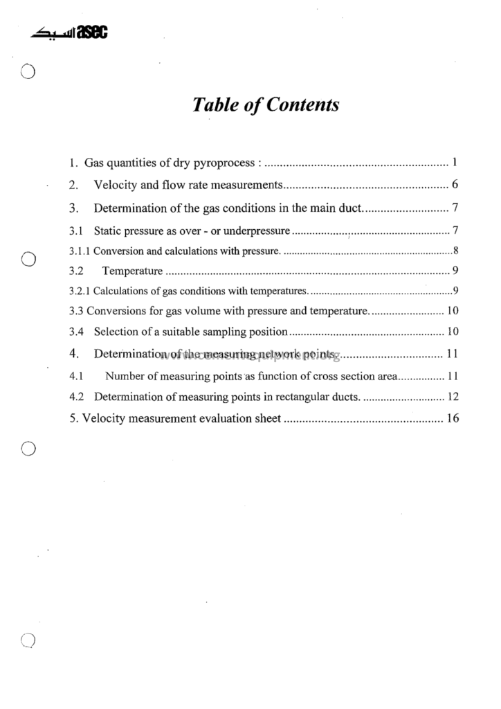
Gas Temperature And Flow Measuring: Complete Guide & Downloa
The gas temperature and flow measurements are the senses of the cement plant: the temperatures of the preheater gas prove the heat exchange, the flows of the kiln and the mill fans set the process conditions, and the two families of the measurements feed the automation that runs the plant: the thermocouple at the kiln inlet, the pitot traverse of the induced draft fan, the multipoint grid of the raw mill duct: the instruments of the file translate the invisible gas streams into the numbers of the control room: the article documents the complete discipline of measuring the gas of the cement line.
The Complete Cement Technical Package (931 files including the books, the courses, the Excel tools and the presentations: $249.99 one-time: instant download via the PayPal payment) includes this measurement file with the instrument catalogues, the error analyses, the calibration procedures and the worked traverses: the engineer follows the article with the file: the principles, the selection, the mounting, the calibration and the maintenance of the gas instrumentation in the one document.
The gas measuring of the plant is a specialist craft with the roots in the classic physics: the thermoelectric laws of the thermocouple, the Bernoulli relation of the velocity pressure and the density corrections of the hot dust-laden gas: this guide walks the reader through the physics first, then the industrial instruments, and finally the cement plant itself: the measuring points of every section and the discipline that keeps their numbers honest.
1. The Role of the Gas Measurements in the Cement Process
The gas measurements serve every department of the plant, and the file opens with the map of their duties:
- The kiln thermal control: the kiln inlet gas temperature at 850 to 1,100 degrees, the preheater gas temperatures by the stage, the calciner at 850 to 900: the temperatures are the primary witnesses of the burning and the targets of the kiln control: the flow of the kiln gases scales the whole thermal balance:
- The mill drying: the raw mill inlet and outlet temperatures (200 to 350 and 90 to 110 degrees) and the gas flow govern the drying and the dew point: the measuring system of the mill duct is the instrument of the drying balance of the earlier chapters:
- The cooler and the fans: the cooler air temperatures and the fan flows define the recuperation and the power consumption: the fan tests of the flows are the basis of the energy audits:
- The emission control: the filter temperatures, the desulfurization lime injection points and the stack flows: the environmental reporting of the plant rests on the flow and the concentration measurements of the file: the emission rate = the concentration x the flow:
The measurements of the file are not the decorative instruments: the process control, the energy accounting and the environmental reporting all depend on the same sensors: the plant that measures its gas well operates well, and the file’s doctrine of the measurement discipline runs through every chapter: the instrument is the contract between the physical reality and the decision.
2. The Temperature Measurement: The Physics and the Units
The temperature measurement rests on the defined scales and the transduction physics:
- The scales: the Celsius scale of the plant practice and the Kelvin of the calculations: the absolute conversions (K = C + 273.15) and the Fahrenheit of the legacy documents: the file’s conversion tables and the order-of-magnitude anchors: the ambient 20 to 30 C, the drying gas 100 to 350, the kiln 1,400 to 1,500, the flame 1,700 to 2,000:
- The transduction families: the thermocouple (the junction voltage), the resistance thermometer (the resistance change), the pyrometer (the radiation), each with its range and its error sources: the selection follows the temperature, the environment and the required accuracy:
- The traceability: the temperature is the traceable quantity: the calibration against the certified reference instruments and the fixed points (the boiling water, the salts, the freezing metals): the calibration chain of the file reaches the national standards:
- The measurement error budget: the sensor error, the mounting error (the radiation, the conduction, the lag) and the transmitter error combine: the good industrial installation controls the total to +/- 2 to 5 degrees in the plant ranges: the file’s error budget examples show the assembly of the uncertainties:
The temperature chapter of the file builds the foundation: the engineer who understands the error sources reads the plant’s temperatures with the respect of their limits: the 1,100 degree kiln gas temperature measured by the thermocouple with the radiation losses reads lower than the truth, and the correction tables of the file quantify the difference: the honest thermometer is the discipline of the mounting and the calibration.
3. The Thermocouples: The Types, the Ranges and the Selection
The thermocouple is the workhorse of the plant’s temperature measurement, and the file documents its science:
- The principle: the Seebeck effect: the two dissimilar metals joined at the measuring junction produce the voltage proportional to the temperature difference against the reference junction: the voltage is small (microvolts per degree) and the cold-junction compensation is the modern transmitter’s duty:
- The type K: the nickel-chromium and the nickel-aluminium pair: the range -200 to +1,200 degrees, the sensitivity 41 microvolts per Kelvin, the cheap and the versatile standard of the mills and the low-temperature plant: the ageing of the type K in the sulfurous gases at the high temperatures is its known limitation:
- The types S, R and B: the platinum-rhodium pairs: the ranges to 1,600 degrees (K, S) and 1,800 (B): the stability and the accuracy of the precious metals, the cost ten times the base metals: the kiln gas and the preheater temperature standards: the B type at the highest kiln services:
- The type N: the nickel-chromium-silicon pair: the improved stability of the K in the moderate ranges, the choice of the heat-treatment plants and the longer campaigns:
- The selection table of the file: the service temperature, the atmosphere (oxidizing, reducing, the sulfur) and the cost rank: the type K for the mill ducts, the type S and R for the preheater, the type B for the kiln shell services: the thermocouple catalogue of the file with the probe lengths and the head types:
The thermocouple chapter of the file equips the engineer for the purchases and the replacements: the thermocouple is the consumable of the plant (the “hot end” probes of the kiln paths last the weeks and the months), and the stock of the file includes the spare probes per position: the thermocouple wiring, the extension cable type matching and the head connections are the details the file standardizes: the little wire is the voice of the 1,500 degree process.
4. The Resistance Thermometers: The Precision of the Moderate Ranges
The resistance thermometer (the RTD) serves the moderate ranges with the unmatched stability:
- The principle: the platinum resistance changes with the temperature with the well-defined curve: the PT100 (100 ohms at 0 degrees) the industrial standard, the PT1000 of the newer transmitters: the resistance measured by the bridge circuits of the transmitters:
- The ranges and the accuracy: the platinum RTD usable from -200 to +600 degrees, with the accuracy class A (0.15 degrees at 0) and class B (0.3): the stability of the platinum resistance out-rivals the thermocouple in the moderate range: the instrument of the mill ducts, the filter lines and the cooler air:
- The construction: the wire-wound and the thin-film elements in the stainless sheaths: the thin-film sensor coil in the mineral-insulated probe: the response times (the thermal lag) documented by the file’s table from the sheath diameter and the insertion depth:
- The wiring: the 2-wire, the 3-wire and the 4-wire connections: the 3-wire compensates the lead resistance and the 4-wire eliminates it: the file’s wiring standard of the plant ensures the lead resistances do not bend the readings of the long cable runs:
The RTD and the thermocouple divide the plant by the service: the RTD below 400 degrees with the precision, the thermocouple above with the simplicity: the file’s instrument selection matrix of the gas temperatures: the mill, the filter, the cooler (RTD), the kiln inlet, the cyclones and the flame (thermocouples and pyrometers): the engineer reads the matrix and the stockroom keeps the two families accordingly.
5. The Radiation Pyrometers: The Temperatures Without the Contact
The hottest services of the plant refuse the contact and the radiation pyrometers read them remotely:
- The principle: the thermal radiation of the hot body measured by the detector: the Planck and the Wien laws relate the radiation to the temperature: the pyrometer sees the emissivity-weighted temperature and the correction of the emissivity is the art:
- The single-wavelength instruments: the infrared thermometers of the mill and the shell scanning: the emissivity setting of the surface (the refractory 0.8 to 0.95, the steel 0.1 to 0.9 by the oxidation) and the corresponding errors: the instruments of the shell scanners of the kiln (the continuous ring temperature profiles of the shell, the refractory failures and the hot spots):
- The two-color pyrometers: the ratio of the radiations at the two wavelengths cancels the emissivity for the grey bodies: the instruments of the flame and the clinker and the kiln inlet: the accuracy in the dirty sight conditions: the preferred of the flame monitoring:
- The sighting discipline: the windows, the purge air and the mounting angles: the dirty window is the silent error of the pyrometers and the air purge system of the file maintains the sight lines: the response and the averaging of the fluctuating flames:
The pyrometry of the file completes the temperature family: the shell scanner watches the refractory, the flame pyrometer watches the combustion and the clinker pyrometer watches the burning zone: the three remote services of the kiln are the chapters of the pyrometry: the radiation measurement, corrected and purged, gives the kiln its hottest truth.
6. The Mounting of the Sensors: The Installation Discipline and the Errors
The mounting of the temperature sensors is the difference between the good and the misleading measurement:
- The immersion depth: the sensor must reach into the gas stream beyond the wall temperature boundary: the rule of the file: the insertion depth 10 to 15 times the probe diameter into the flow, or the insertion in the elbow zones: the short probes of the plant read the wall, not the gas:
- The radiation errors: the hot sensor radiates to the colder walls and reads low in the high-temperature gases: the radiation shields around the probes and the correction calculations of the file: the kiln inlet thermocouple with the shield reads 20 to 50 degrees higher (the truth) than the bare:
- The conduction errors: the heat flows along the probe to the flange and the reading bends: the immersion and the insulation of the probe neck and the head reduce the conduction: the mounting details of the file’s drawings:
- The response lag: the thermal mass of the sheath delays the reading: the thermowell of the RTD slows the response to the tens of seconds and the mill control reacts accordingly: the fast services (the kiln outlet and the control) use the bare or the thin-sheath probes:
- The vibration and the erosion: the probes in the dusty flows wear and the supports vibrate: the probe supports, the wear sleeves and the replacement intervals of the file: the broken probe in the kiln duct is the lost signal of the hour:
The mounting chapter is the quality audit of the measurement: the file’s installation drawings, the immersion tables and the error correction formulas convert the mounting from the craftsmanship to the engineering: the plant documentation includes the positioned probe list of the file with the type, the depth and the expected error for every gas temperature point: the measurement discipline of the file begins at the flange.
7. The Flow Measurement: The Fundamentals of the Gas Streams
The gas flow measurement begins with the physics of the stream, and the file builds the foundation:
- The velocity profile: the gas in the duct flows with the profile: the maximum at the center and the zero at the walls, the profile flatter in the turbulent flows: the point velocity differs from the average and the profile knowledge is the precondition of the measurement: the developed profiles need the straight runs of 5 to 15 diameters before and 2 to 5 after the disturbance:
- The flow definitions: the volumetric flow at the operating conditions (the cubic meters per hour at the actual temperature and pressure) versus the standard flow (the normalized condition, 0 or 20 degrees at 1 atmosphere): the mass flow (kilograms per hour) the conservative quantity across the temperature: the file’s conversions of the three families:
- The density: the flow measurement of the mass requires the density: the density from the temperature, the pressure and the gas composition: the compressibility and the humidity corrections of the file: the gas of the kiln at 300 degrees with the 10 percent water weighs 30 percent less than the dry cold air of the same volume:
- The continuity: the mass is conserved along the duct and through the fans: the balance checks of the plant’s flows (the fan discharge equals the process demand) validate the whole set of the measurements: the file’s flow balance examples of the kiln and the mill circuits:
The fundamentals of the flow chapter give the engineer the language of the readings: the standard and the operating flows, the mass and the volume, the density corrections: the instruments of the following chapters all feed these relations: the flow measurement of the plant is the applied fluid mechanics, and the file’s reference tables carry the density of the common gases across the temperature range: the calculation tools of the package automate the conversions.
8. The Pitot Tube and the Traverses: The Calibration Method of the Ducts
The pitot tube is the reference instrument of the duct flows, and the traverse is its discipline:
- The pitot principle: the total pressure at the impact hole and the static pressure at the side holes: the difference is the dynamic pressure: the velocity from v = sqrt(2 x dp / rho): the single-point reading needs the profile correction and the traverse provides it:
- The traverse method: the log-linear or the log-Tchebycheff point distributions across the duct section: 10 to 20 points of the file’s tables for the ducts and the rectangles: the average velocity from the point average, the flow = the average velocity x the area: the traverse accuracy 2 to 5 percent with the good profile and the careful readings:
- The pitot types: the standard L-shaped pitot, the S-type (the United States Environmental Protection Agency stack pitot) with its calibration constant for the dusty flows: the annubar and the averaging pitots as the permanent versions:
- The dusty service: the pitot holes clog in the dusty gases: the purging connections, the compressed air back-flush and the traverse schedules of the file: the S-pitot of the stacks with the filter probes:
The pitot traverse is the calibration standard of the plant’s flow instrumentation: the annual traverse of the kiln and the mill ducts verifies the continuous instruments and the file’s traverse procedure (the point tables, the velocity calculations and the reporting form) is the audit tool: the traverse of the fan suction and the discharge verify the fan duties of the energy reports: the pitot tube of the file is the trusted ruler of the gas streams.
9. The Differential Flow Meters: The Orifice, the Venturi and the Nozzles
The differential meters measure the flow by the pressure drop across the restriction, and they dominate the clean-gas lines:
- The orifice plate: the thin plate with the concentric bore: the pressure taps upstream and downstream: the flow from the square-root relation of the differential: the compact and the cheap standard of the fuel gas, the air and the water lines: the permanent pressure loss 40 to 70 percent of the differential:
- The venturi: the converging-diverging section with the minimal permanent loss (5 to 15 percent): the instrument of the larger clean flows where the energy matters: the higher cost and the longer installation:
- The flow nozzles: the rounded entrance cones of the moderate loss: the compromise of the two: the instruments of the steam and the air preheaters:
- The calculation and the corrections: the discharge coefficient, the expansion factor and the density corrections of the total: the standard ISO 5167 calculations of the file and its Excel calculator: the differential range 0 to 100 to 500 millibars and the square-root extraction in the transmitter:
The differential meters of the plant measure the purchased energies: the natural gas of the kiln, the compressed air of the silos and the fuels: their calibration and the inspection belong to the trade metering of the plant: the orifice plate inspection (the edge sharpness and the flatness) is the maintenance item of the file: the differential pressure transmitters of the lines, spanned and damped by the file’s commissioning sheet: the square-root law of the orifice is the discipline of their readings.
10. The Modern Flow Meters: The Vortex, the Thermal and the Ultrasonic
The modern instrument families bring the advanced physics to the plant’s services:
- The vortex meters: the bluff body sheds the vortices at the frequency proportional to the velocity: the frequency measured by the sensors in the body: the linear flow signal without the square-root law, the ranges and the accuracy (1 percent) of the modern gas metering: the vortex needs the developed profile and the clean gas: the meter of the natural gas and the instrument air:
- The thermal mass meters: the heated element cooled by the flowing gas: the cooling rate proportional to the mass flow: the direct mass measurement, the sensitivity to the gas composition and the coatings: the instruments of the low-velocity and the constant-composition streams: the compressed air networks and the flare gases:
- The ultrasonic meters: the transit-time difference of the sound pulses with and against the flow: the line-averaged velocity, the no obstruction and the no pressure loss: the meters of the large ducts and stacks with the multi-path arrangements: the accuracy depend on the profile and the installations of the straight runs:
- The selection of the file: the service (clean or dusty), the range, the accuracy, the pressure loss and the cost: the selection matrix places the vortex and the ultrasonic in the large clean lines, the pitot in the dusty ducts, and the orifice in the trade metering:
The modern meters chapter is the contrast to the classic instruments: the plant chooses the family by the service and the economics: the ultrasonic multipath of the new kiln lines brings the 1 to 2 percent flow data to the control system, and the vortex of the fuel gas brings the metering accuracy: the file’s instrument catalogue and the selection matrices guide the new installations and the retrofits: the flow measurement of the future replaces the probes with the fields, and the file keeps the plant on the cutting but honest edge.
11. The Multipoint Measurement of the Large Ducts: The Grids and the Averaging
The large ducts of the cement plant defeat the single-point instruments, and the multipoint systems measure them:
- The averaging pitot arrays: the multiple pitot tubes across the duct manifolded to the common differential transmitter: the average velocity of the section from the geometric weighting: the annubar and the tor-bars of the classic installations:
- The multipoint temperature grids: the thermocouple grids across the large preheater and the mill ducts: the average temperature of the section, the individual points of the grid monitored for the stratification: the grid sensors with the common cold junction and the multiplexed transmitters:
- The integrated flow stations: the full instrument sections: the flow grid, the temperature grid, the pressure taps and the gas sampling probes in the one fabricated spool: the stations of the new plants with the factory calibration and the documented profiles: the stations of the bag filter inlets and the raw mill ducts:
- The verification: the annual traverse against the station readings, the recomputation of the station coefficients and the reporting: the multipoint station without the verification drifts with the fouling and the profile changes: the verification program of the file keeps the stations honest:
The multipoint chapter of the file is the practical answer to the industrial reality: the big ducts of the cement plant have the stratified temperatures and the skewed profiles, and the instruments must see the sections, not the points: the grid designs, the mounting flanges and the calculation methods of the file give the engineer the complete multipoint toolbox: the flows and the temperatures of the big lines, measured section by section.
The retrofit plants install the multipoint systems without the new duct spools: the flange rings welded onto the existing ducts, the grids inserted through the access doors, and the profile verification by the temporary traverse before the final coefficients: the file’s retrofit procedure respects the existing geometry and its flow disturbances, and the verification catches the asymmetric profiles of the patched-up ducts: the old plant gains the modern measurement without the new construction, and the flow station of the retrofit serves the energy audits and the emission reporting from the first year: the multipoint instrumentation of the file adapts to the reality of the existing plants, and the honesty of the profile verification keeps the retrofit numbers trustworthy.
12. The Measuring Points of the Cement Plant: The Map of the Instrumentation
The file maps the measuring points of the complete plant, section by section:
- The preheater tower: the gas temperatures at the stage inlets and the outlets, the riser duct temperatures, the calciner temperature: the thermocouples type S and K of the file’s tower list: the differential pressures of the cyclones as the complementary flow diagnostics:
- The kiln line: the kiln inlet gas temperature, the shell scanning pyrometers, the flame pyrometers, the cooler gas temperatures and the secondary and the tertiary air flows: the kiln gas flow at the induced draft fan by the pitot and the flow stations:
- The mills: the raw mill gas inlet and outlet temperatures and the mill flow stations: the finish mill ventilation temperatures and the separator air flows: the coal mill temperatures with the safety overlays of the CO and the oxygen:
- The filters and the stacks: the bag filter inlet temperatures, the stack flows and the continuous emission monitoring sampling points: the filter gas temperatures and the flows of the environmental reporting:
The point map of the file is the master document of the plant’s instrumentation: the tag numbers, the instrument types, the ranges, the expected values and the calibration intervals per point: the commissioning of the new plants documents the map, and the operating plants maintain it as the living register: the map is the census of the senses: the engineer of the file knows every thermocouple of the tower and every pitot of the ducts by the name and the duty.
The commissioning of a new gas measuring system follows the staged verification of the file: the pre-commissioning inspection of the installations against the drawings, the loop checks of the wiring and the signals, the calibration of every instrument before the operation, and the performance tests with the reference instruments after the start-up: the kiln line commissioning runs the temperature sensors against the certified thermocouples inserted alongside, and the fan systems run the pitot traverses against the new flow stations: the as-built corrections of the station coefficients are the deliverable of the commissioning week: the performance tests then repeat at the operating temperatures, because the radiation and the conduction errors of the hot services differ from the cold checks: the file’s commissioning protocols (the checklist per tag, the loop sheets and the acceptance forms) are the contractual evidence of the measurement readiness: the plants that commission by the file start their operations with the instruments already trusted, and the operators learn the new plant on the verified numbers: the commissioning discipline saves the first year’s false alarms and the wrong decisions that the unverified instruments always bring: the point map, verified at the start, remains the true map of the plant’s senses for the decades of its operation.
13. The Calibration and the Traceability: The Truth of the Instruments
The calibration is the ongoing proof of the measurement truth, and the file defines the program:
- The laboratory calibrations: the dry-block calibrators for the thermocouples and the RTDs (0 to 1,200 degrees), the temperature baths of the low ranges, the dead-weight testers for the pressure transmitters: the calibration laboratory of the plant with the reference equipment certified annually:
- The in-situ verification: the comparison against the reference thermocouples inserted in the ducts, the pitot traverses against the flow stations: the in-situ verifications catch the mounting drift that the laboratory cannot: the schedule of the file pairs the lab and the field checks:
- The traceability chain: the plant references to the certified laboratories, and those to the national standards: the calibration certificates with the uncertainty statements: the audit trail of the file’s records: the calibration history of every tag follows the instrument through its life:
- The acceptance criteria: the calibration tolerances of the file per instrument class: the thermocouple K within +/- 2.2 degrees or 0.75 percent, the RTD class B within its curve, the transmitters within 0.1 to 0.2 percent of the span: the out-of-tolerance instruments loop back to the repair and the re-qualification:
The calibration program of the file is the quality system of the measurements: the annual calibration schedules, the records and the certificates are the evidence of the instrumentation integrity: the plant audits the temperatures and the flows of its process against the calibrated chain: the reporting to the environmental authorities requires the traceable stack measurements: the calibration discipline of the file protects the plant’s data and its permits.
14. The Maintenance of the Measuring Systems: The Fouling, the Wear and the Failure
The gas instruments of the dusty plant fight the service conditions, and the maintenance is their survival:
- The fouling: the dust builds on the probes, the pitot holes clog and the pyrometer windows blind: the cleaning schedules, the purge air systems and the back-flush arrangements of the file: the differential pressure of the fouled stations rises and the trending detects the fouling before the failure:
- The corrosion and the erosion: the sulfurous gases attack the metallic probes, and the abrasive dust erodes the pitot tubes and the flow elements: the material upgrades (the Inconel and the ceramic sheaths of the high-temperature services) and the wear sleeves: the replacement intervals of the file per the service:
- The electrical failures: the cable insulation, the connectors and the transmitter electronics: the moisture and the vibration of the plant: the spare transmitters and the quick-change racks of the file: the redundancy of the critical points (the kiln inlet and the mill temperature) with the voting of the control system:
- The diagnostic strategies: the transmitter diagnostics (the sensor breaks, the out-of-range), the historian trending of the signals and the maintenance alarms: the instrument health monitoring of the file catches the creeping failures: the planned replacements of the consumable probes keep the failures in the calendar, not the night:
The maintenance chapter of the file is the practical partner of the calibration: the two together keep the measurements alive and honest through the campaigns: the instrument crew of the plant works the maintenance lists of the file, and the instrument availability of the good plants exceeds the 99 percent: the measuring systems of the gas circuits, cleaned, repaired and replaced by the plan: the senses of the plant never blink.
15. The Data and the Decisions: The Measurements in the Control and the Reporting
The final chapter of the file follows the measured data into the decisions of the plant:
- The process control: the gas temperatures and the flows feed the controllers of the kiln, the mills and the fans: the control loops of the file tie the temperatures to the fuel and the flows to the dampers: the measurement quality sets the control quality: the validated instruments of the control chain are the audit items of the automation reviews:
- The energy accounting: the heat balances of the kiln and the mills rest on the gas temperatures and the flows: the thermal energy reports of the plant (the gigajoules per tonne of the clinker) derive from the same sensors: the energy audits of the file verify the flows by the traverses before the accounting conclusions:
- The environmental reporting: the stack gas flows with the concentrations give the emission rates: the reporting instructions and the measurement uncertainties of the file support the environmental compliance: the flow measurement of the stack is the regulated quantity, verified by the certified methods:
- The decision culture: the plant that trusts its measurements decides with the data: the file closes with the management philosophy: the calibration budget is the price of the truth, and the truth is the price of the decisions: the instrumentation is not the overhead but the foundation of the plant’s intelligence:
The data chapter ties the thread of the file: the thermocouple of the kiln inlet, the pitot of the fan and the flow station of the mill report into the control system, the energy reports and the environmental files: the decisions of the production, the maintenance and the compliance rest on the measurements the file disciplines: the gas temperature and the flow measuring of the plant is the complete chain from the physics of the metal junction to the decisions of the boardroom: the file is the manual of that chain, and this article its summary: the gases of the cement plant, measured with the science.
The Frequently Asked Questions
Why does the kiln inlet thermocouple read lower than the true gas temperature?
The radiation from the hot probe to the colder surroundings cools the junction below the gas temperature: the bare thermocouple at the kiln inlet reads 20 to 50 degrees low: the radiation shields and the suction pyrometers recover the truth, and the file’s correction tables quantify the mounting error for the standard installations.
How often should the pitot traverse of the kiln fan be performed?
The annual traverse is the industrial practice for the large fan duties, with the additional traverses after the duct modifications or the fan changes: the traverses verify the continuous flow stations and their coefficients: the file’s traverse procedure and the reporting form make the annual audit a routine of the instrument crew.
What is the difference between the volumetric and the mass flow of the kiln gas?
The volumetric flow is the cubic meters per hour at the actual temperature and the pressure, and the mass flow is the kilograms per hour independent of the conditions: the same mass of the kiln gas at 350 degrees occupies nearly double the volume of the cold state: the energy and the emission calculations use the mass flows, and the file’s conversions maintain the distinction.
Can the vortex meter measure the dusty kiln gas?
The vortex meters need the clean gas: the dust erodes the bluff body and the sensors, and the coatings detune the shedding frequency: the kiln and the mill ducts use the pitot and the flow stations with the purging: the vortex serves the clean gas, the compressed air and the fuels: the selection matrix of the file places the families by the service.
How is the pyrometer window kept clean in the dusty services?
The sighting tubes with the continuous purge air keep the windows clean: the purged sight tube with the minimum air velocity of 5 to 10 meters per second at the outlet and the redirected sighting of the pyrometer: the window cleaning at the planned stops and the replacement of the scratched windows: the purge discipline of the file maintains the sight lines.
Does the package include the flow and the temperature calculators and the trackers?
The Complete Cement Technical Package includes the pitot traverse calculator, the orifice calculations, the density conversion tools and the calibration tracker: the 931 files of the package: the engineer of the file computes the traverses and manages the calender with the tools of the same library: the measuring of the gas circuits, calculated and tracked by the book.
Conclusion
The gas temperature and the flow measuring of the cement plant is the science of the sensors and the discipline of their care: the thermocouples and the RTDs at their immersion depths, the pyrometers with their purge, the pitots of the traverses and the stations of the big ducts: the calibration chain and the maintenance calendar keep the numbers true: the process control, the energy accounting and the environmental reporting all drink from the same instruments: the engineer of the file masters the measurement chain from the junction physics to the boardroom number.
The Complete Cement Technical Package includes this measurement guide with the instrument catalogues, the error tables, the traverse procedures and the Excel tools: the 931 files, the $249.99 one-time purchase, the instant download: the temperatures and the flows of the plant, measured with the complete discipline: the senses of the cement plant, sharpened and trusted.
Get this Gas Measuring file + the full 931-file package
$249.99 — one-time purchase, instant download, lifetime access
This file is part of the Complete Cement Technical Package (931 files) available from cementequipment.org. Respective rights holders; library copy for the licensed single user.