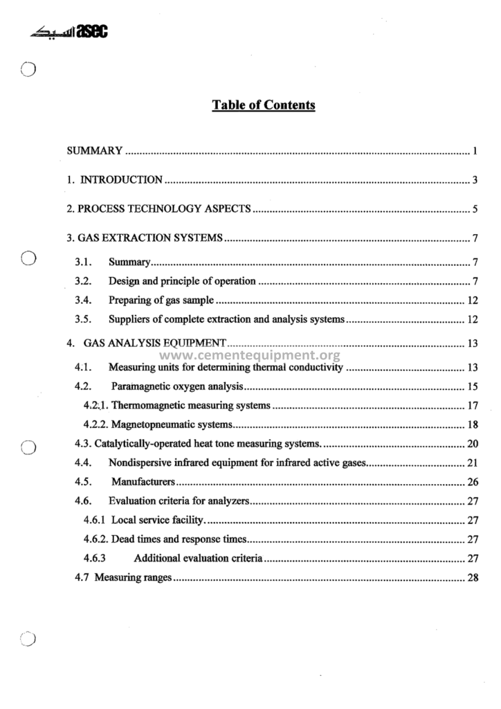
Gas Analyzer: Complete Technical Guide
The gas analyzer guide is the instrument manual of the burning line: the file that explains how the plant measures its combustion gas: the oxygen that flushes the flame, the carbon monoxide that alarms the filter, the nitrogen oxides that the permit limits and the sulfur dioxide that the feed brings: the gas analyzer is the eye of the kiln operator: without its readings the flame is flown blind and the emissions are signed in the dark: this file is the complete course of the gas measurement: the points, the probes, the conditioning, the analyzers, the calibration and the maintenance.
The Complete Cement Technical Package (931 files including the books, the courses, the Excel tools and the presentations: $249.99 one-time: instant download via the PayPal payment) includes the gas analyzer guide with the instrument diagrams, the comparison tables, the maintenance schedules and the troubleshooting sheets: this article walks the file: how the kiln gas is sampled from the hot dusty ducts, how each gas is measured, how the analyzers are calibrated and how the readings are trusted: the reader finishes with the complete picture of the gas analysis chain, from the probe tip in the riser duct to the emission report of the stack.
The gas analysis of the cement kiln is the most challenging sample in the industrial instrumentation: the gas at the kiln exit carries 850-1100°C of temperature and grams of dust per cubic meter, the sample must be cooled, filtered and dried before the analyzer, and every step can distort the reading: the guide treats the whole chain as one system, because the weakest link decides the trust of the number: the same philosophy organizes this article: sampling first, measurement second, calibration third, maintenance everywhere.
1. The Measurement Points of the Kiln Line: Where the Gas Is Read
The gas analyzer file opens with the map of the measurement points, because each point has its own purpose, its own conditions and its own instrument:
- The kiln exit gas: measured in the riser duct or the kiln inlet chamber at 850-1100°C with a dust load of 300-1200 g/Nm3: the most hostile sample point of the line: the O2 and the CO of the kiln exit are the primary combustion controls: the NOx is also read here for the SNCR control;
- The calciner gas: the probe after the calciner or in the riser after the tertiary air addition: the O2 and the CO guard the burnout and the afterburning prevention: the temperature 850-1000°C;
- The tower exit gas: the point after the last cyclone at 290-330°C and 30-100 g/Nm3 of dust: the kindest point of the tower: the O2, the CO, the NOx and the SO2 are read here for the filter protection and the compliance trend;
- The stack: the continuous emission monitoring system (CEMS): the dust, the NOx, the SO2, the CO, the flow and the moisture for the permit: the certified analyzers with the certified quality assurance;
- The raw mill and the coal mill: the CO and the O2 monitoring for the explosion protection: the coal mill gas analysis with the O2 below 12-14% volume as the inert operation standard;
The measurement map of the line is summarized in the table below, with the typical conditions of each point:
| Measurement point | Temperature | Dust load | Primary gases | Instrument duty |
|---|---|---|---|---|
| Kiln exit / riser duct | 850-1100°C | 300-1200 g/Nm3 | O2, CO, NOx | Combustion control, SNCR |
| Calciner riser | 850-1000°C | 200-800 g/Nm3 | O2, CO | Burnout of the fuel split |
| Tower exit (after last cyclone) | 290-330°C | 30-100 g/Nm3 | O2, CO, NOx, SO2 | Filter protection, trend |
| Stack | 90-130°C | Below 10 mg/Nm3 | Dust, NOx, SO2, CO, flow | Certified emission reporting |
| Coal mill outlet | 70-100°C | Coal dust | O2, CO | Explosion protection interlocks |
The measurement map is the start of every combustion troubleshooting: the guide draws the points on the line diagram with their typical gas compositions and their instrument duties, so the reader places every analyzer of the plant in its purpose: the same map organizes the calibration and the maintenance calendar of the file.
2. The Kiln Exit Sampling and the Sample Conditioning: The Hottest Probe of the Plant
The kiln exit sample is the extreme case of the gas analysis, and the guide gives it the attention the extremes deserve:
- The conditions: 850-1100°C, dust 300-1200 g/Nm3, alkalis and sulfates that condense on the cool walls, and the probe inserted into the turbulent riser flow: the sample point selection and the probe length follow the velocity profile rules of the guide;
- The probe: the ceramic or the high-alloy steel probe with the sintered metal or the ceramic filter at the tip: the heated probe body keeps the sample above the dew point of the corrosive components;
- The blowback: the automatic reverse air pulse, typically every 5-30 minutes, that cleans the probe filter: the blowback pressure, the duration and the intervals are tuned per plant and the guide gives the starting values and the tuning criteria;
- The rotary sampling valve: the multi-line systems rotate the sampling between the probe lines so the blowback does not starve the analyzer: the rotary valve sequence and its maintenance are documented with the cycle diagrams;
- The sample transport: the heated sampling line at 150-200°C that prevents the condensation of the water, the SO3 and the alkalis between the probe and the analyzer cabinet: the line length, the heat tracing and the insulation standards of the guide;
The kiln exit sampling chapter is the respect paid to the harshest measurement: the plants that neglect the probe plugging and the blowback discipline live with the wrong O2 readings and the false alarms, and the guide’s message is blunt: the most expensive analyzer is the one fed by a plugged probe.
Between the probe and the analyzer sits the conditioning cabinet, the unit that makes the sample compatible with the instruments, and the guide details every function it performs:
- The primary filter: the ceramic or the sintered metal element that takes the sample to below 1-5 mg/Nm3 of dust: the filter housing with the automatic cleaning and the drain;
- The sample cooler: the gas chiller that drops the sample temperature from the transport line to 3-5°C, condensing the water vapor: the condensate separator and the peristaltic pump drain: the cooler is chosen for the gas flow of the analyzers, typically 2-6 liters per minute;
- The final filter: the fine filter before the analyzer train: the protection of the analyzer cells from the residual dust and the droplets;
- The flow control: the needle valves, the rotameters and the flow alarms that distribute the sample to the analyzer channels: the flow of 1-3 liters per minute per analyzer with the stable pressure;
- The pump: the diaphragm or the peristaltic pump after the cooler, pulling the sample through the whole train: the pump location after the cooler is deliberate, so the wet parts stay before the drier analysis;
- The calibration manifold: the solenoid valves that switch the analyzer feed between the sample, the zero gas and the span gas during the automatic calibration: the calibration sequence of the plant is executed through this manifold;
The conditioning is where the measurement is won or lost: a wet analyzer cell reads wrong, a dusty cell reads late, a leaking fitting reads the room air instead of the kiln: the guide’s conditioning chapter is the difference between the instrument that is trusted and the instrument that is suspected.
3. The Oxygen Measurement: The Paramagnetic and the Zirconia Methods
Oxygen is the master variable of the combustion control, and two measurement principles serve the cement plants:
- The paramagnetic analyzer: the classic extractive method: oxygen is paramagnetic, attracted by the magnetic field, and the analyzer senses the resulting pressure or the magnetic wind in a dumbbell or a magneto-pneumatic cell: the paramagnetic analyzer reads 0-25% O2 with the repeatability of about 0.1% and requires a dry sample: the workhorse of the kiln exit and the tower exit measurements;
- The zirconia in-situ probe: the zirconium oxide cell heated at 650-750°C that measures the O2 directly in the duct: the Nernst voltage across the cell against the reference air gives the oxygen concentration: the in-situ probe avoids the sampling chain entirely and responds in seconds: the zirconia probes suit the cleaner points like the tower exit and the raw mill, and the heated versions tolerate the moderate dust;
- The ranges and the accuracy: the operating O2 setpoints of the line: kiln exit 1.5-2.5%, tower exit 2.5-3.5%, calciner 1.5-3.0%: the analyzer accuracy of 0.1-0.2% O2 and the span calibration with the bottled gas: the guide tabulates the required accuracies against the control setpoints;
- The application choice: the extractive paramagnetic for the hot kiln exit points with the heavy dust, the zirconia probe for the cleaner medium-temperature points where the fast response saves the control: the comparison tables of the guide put the two principles side by side with the maintenance cost and the response time;
The two principles are compared on the decisive criteria of the plant in the table below:
| Criterion | Paramagnetic (extractive) | Zirconia (in-situ) |
|---|---|---|
| Measuring principle | Magnetic susceptibility of O2 in a dumbbell cell | Nernst voltage of the heated ZrO2 cell at 650-750°C |
| Sample preparation | Full conditioning train: filter, cooler, dry sample | Direct measurement in the duct, no sample line |
| Response time | Minutes (through the sampling train) | Seconds |
| Typical range | 0-25% with 0.1% repeatability | 0-21%, best performance 0-10% |
| Best location | Kiln exit, calciner, heavy dust points | Tower exit, raw mill, moderate dust points |
| Maintenance | Filter and cooler service, calibration gas | Cell aging, probe cleaning, occasional replacement |
The O2 measurement decides the excess air of the line: the analyzer that drifts downward forces the operator to over-air the kiln, wasting the fuel; the analyzer that drifts upward lets the CO rise: the O2 calibration discipline of the guide pays for itself weekly, and the guide says so with the fuel arithmetic.
4. The Carbon Monoxide Measurement: The NDIR Method and the Alarms
CO is the alarm gas of the plant: the filter protection and the combustion completeness both depend on its measurement:
- The NDIR principle: the nondispersive infrared analyzer: the sample cell is traversed by the infrared beam, and the CO molecules absorb at 4.6 micrometers: the absorption is proportional to the concentration: the dual-beam and the gas-filter-correlation versions compensate the interference of the water vapor and the CO2;
- The ranges: the CO analyzers of the kiln lines span 0-500 ppm for the precision control and 0-5000 ppm for the alarm applications: the resolution of a few ppm and the response of 5-20 seconds with the sample conditioning;
- The cross-interference: the CO2 at 15-30% in the kiln gas broadens the CO absorption band: the gas filter correlation technique cancels the CO2 interference: the guide explains why the simple IR analyzers read false CO on the cement kiln gas and when the laser-based analyzers are justified;
- The tunable diode laser (TDL): the emerging in-situ technique: the laser beam crosses the duct and measures the average CO across the path, avoiding the extraction entirely: the TDL suits the large square ducts where the point sample is not representative: the guide includes the comparison of the TDL versus the extractive NDIR;
- The alarm philosophy: the CO setpoints of the tower exit for the filter protection, the CO interlocks with the ESP at 0.5-1.0%, the CO monitoring of the coal mill and the raw mill for the explosion prevention: the alarm hierarchy and the operator response of the guide;
The CO measurement chapter closes with the data interpretation: the CO spikes after the feed breaks, the CO plateau during the transient conditions, the CO rising with the calciner overfueling: the pattern library of the file lets the operator read the combustion events from the CO trace, the skill of the experienced kiln man, documented and transferable.
5. The Nitrogen Oxides: The Chemiluminescence and the UV Analyzers
NOx is the pollutant of the modern permits, and its analyzer is the most specialized instrument of the gas train:
- The chemiluminescence analyzer: the reference method: the sample NO reacts with the ozone in the reaction chamber, the reaction emits light, and the photomultiplier measures the light intensity proportional to the NO concentration: the NO2 is first converted to NO in a heated molybdenum converter at 300-350°C, so the analyzer reads the total NOx: the ranges of 0-100 to 0-2000 ppm are covered with the response of a few seconds;
- The sensitivity and the interference: the chemiluminescence analyzer is the most sensitive and the most specific: the NH3 interference of the SNCR operation must be understood, and the guide documents the test procedures with the ammonia solutions;
- The UV analyzers: the ultraviolet absorption instruments that measure the NO and the SO2 together in the same cell: the modern multi-component UV analyzers serve the CEMS where the space and the cost matter: the comparison with the chemiluminescence in the guide’s tables;
- The NOx measurement points: the kiln exit for the SNCR control at 850-1000°C, the stack for the compliance: the two points answer different questions: the kiln exit guides the ammonia injection, the stack reports the permit: the guide teaches both configurations and their data flows;
The NOx analyzer chapter includes the weekly and the monthly verification routines: the zero and the span with the certified gas mixtures, the converter efficiency test, and the response time checks: the SNCR dosing depends on this instrument, and the dosing economics are the chapter’s closing argument: a drift of 20 ppm in the NOx reading moves the ammonia consumption by visible percentages.
6. The Sulfur Dioxide: The UV Fluorescence and the Electrochemical Cells
SO2 completes the pollutant quartet, and its analysis has its own challenges in the cement gas:
- The UV fluorescence: the standard principle: the SO2 molecules absorb the ultraviolet light and re-emit at the longer wavelength, the fluorescence measured by the photomultiplier: the sensitivity of 0.1-1 ppm in the ranges of 0-100 to 0-500 ppm;
- The sample conditioning for SO2: the critical difference: the SO2 is soluble in water, so the condensed droplets must not touch the sample: the sample is kept warm until the chiller and the condensate is separated immediately: the guide’s conditioning section for the SO2 is stricter than for the other gases, because the dissolved SO2 vanishes from the gas phase and the reading drops;
- The electrochemical cells: the portable and the personal instruments: the solid-state cells of the hand-held gas analyzers used for the duct traverses and the leak checks: the cell drift is faster, and the guide gives the factory calibration intervals;
- The SO2 in the cement context: the SO2 at the tower exit ranges from the single digits of milligrams per normal cubic meter when the alkalis absorb it, to the hundreds when the pyrite sulfur of the feed oxidizes in the preheater: the analyzer readings are the continuous witness of the sulfur balance of the line;
The SO2 chapter connects the analyzer to the desulfurization decisions: the lime injection systems are dosed on the SO2 readings, and the guide covers the dosing control loop and the response time requirements of the analyzer in that loop: the SO2 measurement is both the compliance instrument and the process instrument.
7. The Continuous Emission Monitoring System: The CEMS of the Stack
The stack measurement is the certified face of the plant, and the guide devotes a full chapter to the CEMS:
- The components: the dust monitor (the opacity or the light scattering), the gas analyzers for the NOx, the SO2 and the CO, the flow meter, the temperature and the moisture sensors: the data acquisition system that computes the mass emission rates in kilograms per hour;
- The quality assurance: the monthly zero and span checks, the quarterly relative accuracy test audits against the reference methods, the annual certification: the QA schedule of the guide follows the international practice of the EN and the EPA-style frameworks without pretending to quote the legislation of any single country;
- The data handling: the half-hourly averages, the daily averages, the validity flags: the data recovery rules when the analyzer is in the maintenance: the availability requirement of the CEMS, typically above 90-95% of the operating time;
- The moisture correction: the measured concentrations are converted to the dry basis with the moisture measurement: the oxygen reference of 10% is applied to the NOx and the SO2 values per the cement practice: the conversion formulas and the worked examples fill the reference tables;
The CEMS chapter is the document the plant engineer hands to the auditor: the same data that the operator watches in the control room is the data of the permit report, and the guide makes the connection explicit: the stack analyzer is the last witness of the combustion quality of the whole line.
Beside the fixed stack instruments stands the portable family, the moving witness that keeps the fixed one honest, and the guide covers both as one measurement system:
Not all the measurements are fixed: the portable analyzer complements the installed instruments in the balance campaigns and the troubleshooting:
- The handheld and the transportable analyzers: the electrochemical and the NDIR instruments with the built-in pumps and the sample conditioning: the O2, the CO, the NO, the SO2 in the portable suitcase format;
- The duct traverses: the measurement of the gas composition and the velocity across the duct cross-section per the standard traverse grids: the kiln exit gas velocity profile, the cooler false air quantification, the preheater duct leak hunting: the traverse data of the balance campaign reconstruct the air balance of the line, stage by stage;
- The false air measurement: the classic leak detection with the O2 or the CO2 profiles: the false air into the kiln hood, the cooler front and the cyclone offtakes raises the exit volumes and costs the fan power: the guide quantifies the false air penalty: every percent of the false air at the tower inlet raises the gas volume by roughly the same order of magnitude, and the kiln lines of the real world lose 5-15% of their gas to the leaks;
- The combustion survey: the annual audit of the line with the portable instruments that recalibrates the fixed analyzers and the control setpoints: the survey report format of the guide: the traverse map, the measured profiles, the comparison with the control room values and the correction actions;
The portable chapter makes the plant independent of the fixed instrument’s opinion: the audit trail of the gas analysis is the professional habit the guide installs: the traverse once per quarter, the fixed analyzers verified against the portable, and the line’s air balance reconstructed from the measurements rather than the assumption.
8. The Calibration and the Drift: The Gas Standards, the Zero and the Span
The accuracy of the gas analyzer rests on the calibration discipline, and the guide is explicit about the gases, the intervals and the records:
- The zero gas: the nitrogen or the synthetic air per the analyzer type: the zero check establishes the baseline: the zero drift of the NDIR and the paramagnetic analyzers is the most common failure, driven by the cell temperature and the aging of the source;
- The span gas: the certified mixture in the measuring range of the application: the O2 span at 5.0 or 20.9% (the ambient air), the CO span at 300-1000 ppm, the NOx span at 100-500 ppm: the certified cylinders with the certificate of analysis, the expiration dates and the traceability to the national standards;
- The automatic calibration: the timed sequence of the zero and the span through the calibration manifold, typically every 8-24 hours with the automatic compensation of the drift: the calibration records with the timestamps and the results: the trend analysis of the drift itself is a diagnostic of the analyzer health;
- The manual verification: the daily spot check by the shift and the monthly full calibration by the instrument technician: the guide’s maintenance plan assigns the tasks to the shifts and the calendars;
- The linearity and the response checks: the multi-point verification every quarter with the intermediate gas concentrations: the response time measurement: the cell cleaning and the replacement criteria of the consumable parts;
The calibration chapter closes with the trust argument: the gas analyzer is the only instrument of the plant that the operator cannot cross-check by eye, and its numbers carry the fuel flow, the ammonia dosing and the permit status: the calibration record is the legal and the technical instrument of that trust: the guide treats the calibration log as a process document, not a paperwork chore.
9. The Maintenance Calendar and the Troubleshooting of the Gas Analysis
The measurement chain is mechanical before it is electronic, and the maintenance calendar of the guide follows the wear of the real parts:
- The daily checks: the sample flows, the blowback pressure, the cooler temperature at 3-5°C, the condensate draining, the alarm log review: the fifteen-minute round of the plant’s gas analysis routine;
- The weekly checks: the visual inspection of the probe tip and the filter, the zero check of the main analyzers, the leak test of the sample train: the guide provides the checklists in the printable format;
- The monthly checks: the full span calibration, the converter efficiency test of the NOx analyzer, the bag change of the final filters, the pump diaphragm inspection;
- The quarterly and the annual: the multi-point linearity, the traverse verification by the portable instruments, the probe replacement on the wear intervals, the accuracy test audit of the CEMS: the guide’s annual schedule integrates with the plant shutdown calendar, because the kiln exit probes are only safely serviced at the stops;
- The troubleshooting tables: the slow response, the drifting zero, the impossible CO values, the water in the analyzer: each symptom page lists the causes, the checks and the fixes in the decision-table format: the guide is the field book of the instrument technician;
The maintenance chapter is the largest of the file, and deliberately: the gas analysis chain consumes the maintenance budget in the probes, the filters and the pumps, and the guide teaches the economy of the intervals: the parts replaced on the schedule fail rarely, and the parts neglected fail always, at the worst moment: the shutdown-week rule of the file.
10. The Gas Analysis in the Control Strategy: From the Readings to the Actions
The final chapter of the guide ties the instruments to the process: what the readings mean and what the control loops do with them:
- The O2 loops: the kiln exit O2 to the kiln fuel or the kiln feed control, the calciner O2 to the tertiary air damper: the setpoints and the deadbands of the standard control schemes, with the response times of the analyzers as the loop design constraint;
- The CO limit logic: the CO override that trims the fuel when the CO rises: the anti-hunting settings and the interaction with the NOx loops: the multivariable challenge of the kiln combustion control;
- The SNCR on the kiln exit NOx: the ammonia or the urea dosing cascade with the measured NOx as the primary, the temperature window as the constraint: the analyzer reliability requirements of the dosing loop, and the fail-safe strategy when the analyzer fails;
- The interlock philosophy: the measuring-point failures downgrade the control to the manual: the guide’s philosophy of the instrumented safety: no analyzer, no automatic fuel: the redundancy of the critical analyzers is recommended with the exact argument of the risk, and the guide gives the redundancy levels for each measurement point;
The control chapter shows the gas analyzer as the sensor of the combustion economy: the setpoints it feeds, the ammonia it doses and the alarms it guards: the modern kiln line without the gas analysis is a vessel without eyes, and this file is the course that installs the eyes and keeps them calibrated: the readings, the loops and the trust.
11. The Gas Analysis of the Coal Mill and the Explosion Protection
The coal grinding is the most explosive section of the cement plant, and its gas analysis is a safety instrument before it is a process instrument: the guide covers the coal mill measurement train with the same depth as the kiln:
- The oxygen control: the coal mill operating with the hot kiln gas as the drying medium must hold the oxygen below the flammability limit: the O2 setpoints of 11-14% volume in the mill outlet gas are the standard practice before the safety interlock tripping at the higher values: the zirconia probe or the extractive paramagnetic analyzer with the fast response serves the mill control;
- The CO monitoring: the carbon monoxide in the mill outlet rises during the incipient smoldering of the coal deposits: the CO alarm at 200-500 ppm with the mill trip logic is the classical early warning: the CO analyzer of the coal mill is calibrated more often than any other, because the safety depends on its truth;
- The sampling challenges: the dusty, warm and moist gas of the mill outlet: the probe cleaning cycles and the heated lines: the sample point after the mill filter, where the dust is lower and the response still fast enough: the guide gives the point selection criteria;
- The protection philosophy: the analyzer readings interlock with the mill feed stop, the inerting with the nitrogen or the steam, and the extinguishing systems: the redundancy of the critical CO and the O2 measurements is the norm: the guide explains the fail-safe principle: the analyzer failure must close the mill, never open it;
- The bunker and the silo gases: the CO and the O2 monitoring of the coal silos with the venting and the inerting equipment: the temperature probes in the silo mass complement the gas analysis: the guide’s coal storage chapter unites the measurements with the operating rules of the fuel stock;
The coal mill section is where the gas analysis proves itself as a safety device: the plants that measure their mills correctly sleep well, and the plants that do not learn the value of the measurement in the fire reports: the guide states the numbers and the logic without drama, and the reader takes the discipline home.
And the last discipline is the life of the numbers themselves: the recording, the archiving and the quality of the analysis data, because the data is used by the process, the energy and the environment departments at once:
- The control room recording: the analyzers feed the DCS with the analog and the digital signals: the measured values, the calibration states and the validity flags are recorded with the seconds resolution: the trend archives of the last months support the combustion reviews and the troubleshooting histories;
- The data validity: the analyzer data carries the status: in service, in calibration, in maintenance, invalid: the data quality flags prevent the control loops and the reports from using the dead values: the guide teaches the flag philosophy and the operator’s discipline of checking the analyzer status before reading the number;
- The emission reports: the CEMS data aggregated into the half-hourly and the daily averages, the exceedance handling and the availability statistics: the report generation and the archiving per the permit requirements: the guide helps the plant produce the report the authorities trust, with the complete metadata: the analyzer identity, the calibration records and the maintenance notes;
- The long-term records: the monthly and the yearly summaries of the combustion parameters: the O2 averages, the CO peaks, the NOx emissions per ton of clinker: the historical series support the energy audits and the permit renewals: the guide’s reporting formats are ready to use, and the data structures of the file align with the balance workbooks of the package;
The data chapter closes the file with the professional promise: the gas analysis is only worth what the data management preserves: the numbers that are logged, validated and archived become the knowledge of the plant, and the knowledge of the plant is the difference between the operation that reacts and the operation that plans: the guide ends its teaching there, with the record as the memory of the combustion, kept the way the kiln deserves.
12. The Analyzer Selection for the New Line: The Specification Checklist
The guide closes its technical body with the specification discipline: the selection of the gas analysis equipment for a new line or the replacement of an old instrument is a page of decisions, and the file converts them into a checklist:
- The point conditions first: the temperature, the dust, the moisture and the corrosives of the sample point decide the probing and the conditioning system before any analyzer brand: the guide’s point survey form collects the conditions and the measurement purpose in one page: the right system for the wrong conditions fails at the start, and the guide refuses to let that happen;
- The measurement purpose: the control analyzer versus the compliance analyzer: the control applications emphasize the response time and the reliability, the compliance applications emphasize the certification and the quality assurance: a single analyzer can rarely serve both purposes, and the guide marks the distinction with the instrument selection tables;
- The environment of the analyzer house: the climate control, the dust protection, the power quality and the air conditioning of the analyzer cabin: the analyzer lives where the maintenance technician works, and the guide’s cabin specification keeps the instruments within their humidity and temperature windows for the full operating year;
- The spares and the serviceability: the critical consumables (the probes, the filters, the pumps, the cells) with the stock levels, the local service access, the documentation and the training: the review of the installed base of the region: the guide’s evaluation matrix ranks the offers on the lifecycle criteria, not the first price;
- The acceptance and the commissioning: the factory acceptance, the site installation inspection, the commissioning tests with the certified gases, the response time measurements and the documentation handover: the acceptance protocol of the guide follows the same quality standards it taught for the calibration, from the first day of the instrument’s life;
The specification chapter is the practical graduation of the file: the reader who can specify, commission and maintain the gas analysis chain is the complete gas analysis engineer, and the guide has taken him there: the checklist is the tool he keeps for every future project, from the single analyzer replacement to the full CEMS of the new line: the measurement future of the plant, specified with the rules of this file.
13. The Frequently Asked Questions
What instrument measures the O2 in the cement kiln gas?
The standard instrument is the extractive paramagnetic analyzer, which is immune to the CO2 and the hydrocarbons and reads with the accuracy of about 0.1% in the dry sample: the in-situ zirconia probes measure the O2 directly in the duct and are applied at the cleaner points where the fast response matters: the two principles cover the plant, and the guide compares them for each measurement point.
How often must the gas analyzers be calibrated?
The automatic zero and span cycle typically runs every 8-24 hours with the certified gases, the daily spot checks by the shift confirm the reading, and the full manual calibration with the multi-point verification runs monthly or quarterly per the instrument: the certified CEMS analyzers follow the stricter quality assurance schedule with the quarterly test audits: the calibration intervals are a function of the measured drift, and the guide teaches the drift tracking that extends the intervals safely.
Can the CO analyzer measure through the water vapor of the kiln gas?
The water vapor interferes with the infrared CO absorption and the condensation damages the cell, so the sample is cooled and dried before the analyzer: the remaining residual moisture is compensated by the gas-filter-correlation technique of the modern instruments: the in-situ laser analyzers measure the CO across the duct in the wet hot gas directly, which is their advantage in the applications where the extraction is impractical.
Why is the SO2 reading lower when the sample cooler leaks?
SO2 dissolves readily in the condensed water, so a leaking cooler or a wet sample train absorbs the SO2 and the analyzer reads low: the SO2 sample conditioning keeps the gas warm until the chiller and separates the condensate immediately: a suspicious SO2 reading is tested by checking the whole sample train for the moisture, not by distrusting the analyzer alone: this is the classic trap of the SO2 measurement, documented in the guide.
What is the response time the gas analyzers need for the kiln control?
For the O2 and the CO combustion loops the T90 response of 10-30 seconds through the extractive systems is the accepted practice: the in-situ zirconia and the laser analyzers respond in 1-5 seconds: for the SNCR dosing the NOx response time below 60 seconds is adequate; the faster instruments reward the line with the tighter control and the lower ammonia consumption: the response time specification is a design number of every application chapter of the guide.
14. Conclusion
The gas analyzer guide of the package is the complete course of the kiln gas measurement: the sampling from the hostile ducts, the conditioning of the sample, the principles of the O2, the CO, the NOx and the SO2 analyzers, the certification of the stack systems and the calibration discipline that makes the readings trustworthy: the engineer who studies the file can design the measurement train of a new line, maintain the analyzers of an existing one and audit the whole gas analysis chain with the portable instruments.
The gas readings are the language between the kiln and the operator: the O2 says how the flame breathes, the CO says when the combustion stumbles, the NOx says what the permit allows: the plant that reads its gas correctly burns its fuel at the exact excess and doses its ammonia at the exact rate, and the savings of that precision appear in the fuel bill and the emission report every month: the Complete Cement Technical Package includes this guide with the instrument diagrams, the comparison tables and the maintenance schedules, in the 931-file library at $249.99 one-time, the instant download via the PayPal payment: the gas analysis of the plant, mastered.
Get this Gas Analyzer guide + the full 931-file package
$249.99 — one-time purchase, instant download, lifetime access
This file is part of the Complete Cement Technical Package (931 files) available from cementequipment.org. Respective rights holders; library copy for the licensed single user.