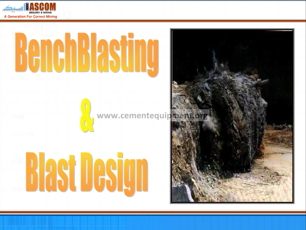
Bench Blasting: Complete Technical Guide
Bench blasting is the very first size-reduction stage of every dry-process cement plant: the controlled release of explosive energy that breaks the limestone or the marl of the quarry into fragments the primary crusher can accept: the whole economics of the plant depend on this first break: the drill holes, the burden and the spacing, the charge column, the delay sequence and the stemming of each blast decide the cost per ton of raw material, the digging rate of the excavator, the throughput of the crusher and the wear of every item downstream of the shot: for this reason the quarry blasting practice is not an isolated field operation but a design discipline that feeds the plant with the correct chemistry and the correct fragmentation, day after day, month after month.
The Complete Cement Technical Package (931 files covering the quarry, the crushing, the raw grinding, the kiln and the finish systems: $249.99 one-time: instant download via the PayPal payment) includes this full bench-blasting file with its tables, its calculations and its worked examples: the document is written for the quarry engineer and for the production manager who must approve the blasts, read the vibration reports and solve the daily problems of the flight: the article walks the file: the geometry of the bench, the drilling fleet, the explosives, the initiation systems, the design calculations, the environmental limits, the selectivity for chemistry and the troubleshooting of the misfires and the oversized blocks: by the end of the article, the reader holds the complete method of the controlled bench blast in the cement raw material quarry.
The cement quarry is different from the metal mine in the way the blasting is judged: the metal mine blasts for the minimum cost per ton of ore, while the cement quarry blasts for the mixture of the chemistry and the size: the limestone, the marl and the clay are blasted in the same shot or in adjacent shots to keep the raw mix on target, and the fragmentation must satisfy the jaw or the gyratory crusher that follows: with these two masters, the blasting engineer of the cement plant builds the pattern, chooses the explosive and measures the results: this guide explains all the numbers of that work.
1. The Principles of the Bench Blasting: from the Free Face to the Echelon Detonation
The bench blast works with one fundamental requirement: a free surface, called the free or the charge face, perpendicular to the burden: the explosive column inside the drill hole is detonated at the bottom, and the detonation product gases expand and crack the rock along the radial and the tangential planes: the blocks break toward the free surface, which offers the minimal resistance, and the entire slice of the bench falls and expands into a muck pile: the process repeats: the bench is reduced in successive slices 10 to 20 m wide, the excavator removes the muck, and the face recedes.
The mechanics of the rock breakage during the blast follow the sequence of the interaction:
- The detonation: the shock front travels down the column at the velocity of detonation (VOD) of the explosive, typically 3,000 to 6,000 m/s, and the explosive converts into high-pressure gas at 5 to 15 GPa;
- The shattering: the shock passing through the immediate rock creates the crushed zone of a few hole diameters around the charge and the radial cracks that propagate into the rock;
- The expansion: the gas pushes the cracked rock body, the radial cracks open, the flexural cracks connect to the free face, and the block bulges, tilts and heaves outward from the bench;
- The fragmentation: the primary fragments are struck by the coincidences of the cracks, and the particles are further split by the flight and the impact during the fall: the muck size distribution of the result;
The quality of the blast is judged of the effort by the fragmentation (the passing D80 of the muck in millimeters), the looseness of the pile, the oversize percentage, the toe remaining at the bench foot, the vibration in the surroundings and the cost: the file keeps these five measures at the center and every design parameter of the book attaches to at least one of them.
2. The Geometry of the Bench: The Height, the Face Angle, the Ramp and the Floor
Before the pattern of the drill holes is designed, the bench itself is defined by the four lines:
| Bench element | Typical value in the cement quarry | Notes |
|---|---|---|
| Bench height H | 10 to 15 m | selected with the excavator reach |
| Bench face angle | 70 to 85 degrees | working face, established after each blast |
| Final slope angle | 45 to 60 degrees | stability of the permanent wall |
| Bench width | 25 to 40 m | operating width for the excavator and the truck |
| Grade (floor) width | 8 to 12 m | for the haul road at the foot |
The bench height is determined by the reach of the excavator and the drill: a 15 m bench with a large rear digging excavator is the classic: the height must satisfy the stability of the wall between the checks and must not exceed the reach of the drilling mast: benches of 10 to 15 m dominate the cement quarries of the world because the 90 to 250 ton excavators handle them efficiently and the drill rigs drill in a single pass or with one joint bar.
The face of the bench is never perfectly vertical after the blast: the angle of the face is measured after each shot and registered, because the design of the next pattern uses the actual face line, not the theoretical: a face that has developed a convex shoulder (the crest overhang) requires the cleaning before the next drill, and a face with the back-break receives the holes re-drilled at a steeper angle: the geometry bookkeeping of the bench plan is as careful as the chemistry bookkeeping of the plant.
3. The Primary Variables of the Blast Design: The Burden, the Spacing, the Hole Diameter
The three numbers that define the pattern are the burden, the spacing and the hole diameter:
- The burden B: the shortest distance from the charge hole to the free face: the burden is the hardest variable of the design because it decides the amount of rock the hole must move: the burden too large and the face does not break and the stemming area throws the gases into the air, the burden too small and the energy is wasted in the over-crushing of the toe zone;
- The spacing S: the distance between two adjacent holes of the same row, measured parallel to the face: the spacing and the burden share the area of a hole: the rule of the industry says the ratio S/B of 1.0 to 1.5: the wider the spacing, the coarser the muck between the holes;
- The hole diameter d: the driving work of the block efficiency: the larger the diameter, the larger the burden per meter (B = 30 to 40 x d) and the cheaper the hole cost per ton, but the coarser the fragmentation and the higher the vibration per hole;
- The sub-drill (sub-grade): the depth below the foot of the bench, 0.2 to 0.5 x B, to break the toe rock without the floor left in ridges;
- The stemming height (t): the inert place on the top of the charge, 0.7 to 1.0 x B of crushed stone or the drill cuttings, to confine the gases;
The design sequence of the file: hole diameter from the drilling fleet; the burden from the diameter (B = 30 to 40 d); the spacing from the burden (S = 1.1 to 1.3 B for the square grid, S = 1.4 to 1.6 B for the corrid layout); the bench height from the geometry; the sub-drill and the stemming length from the burden: the numbers of the whole pattern flow from these five statements, and the file gives them all in the printable form.
4. The Example Pattern of the 12 m Bench: The Numbers of a Production Blast
The worked example of the typical cement quarry blast, presented in the file with full notes:
| Parameter | Value | Formula used |
|---|---|---|
| Bench height H | 12 m | planning |
| Hole diameter d | 115 mm | verify the 251 mm drill rig capacity |
| Burden B | 3.5 m | B = 30 x d |
| Spacing S | 4.2 m | S = 1.2 x B |
| Sub-grade SB | 1.0 m | 0.3 x B |
| Stemming T | 3.0 m | 0.85 x B |
| Hole depth | 13.0 m | H + SB |
| Charge length LCh | 10.0 m | 13.0 – 3.0 |
| Charge per meter | 9.3 kg/m | an explosive loading 9.3 kg/m at 115 mm |
| Charge per hole | 93 kg | 10.0 x 9.3 |
| Rock per hole | 1,340 tons | H x B x S = 12 x 3.5 x 4.2, density 2.6 |
| Powder factor | 0.45 kg/t | charged 0.45 kg/t within the industry range |
The example shows the complete arithmetic chain of the design: the 40 holes of the blast break 53,600 tons of rock in a single round with 3.7 tons of explosive: the powder factor of 0.4 to 0.5 kg/t is the working range of the hard limestone: the same pattern with the explosive of the marl layers (0.25 to 0.35 kg/t) would produce the dust and the quick; the final selection of the pattern is always verified by the first test blast and adjusted on the basis of the observed muck: the file keeps the forms of the test blast documentation.
5. The Drilling: The Rigs, the Bits, the Penetration and the Patterns
Drilling is the most expensive element of the blasting operation in the man-hours and in the steel, and the accuracy of the drill decides the accuracy of the loads:
- The rotary drill rigs: the largest class with the tricone bits, 115 to 251 mm, penetration rates 10 to 30 m/h in the soft to medium limestone: the dust collectors and the automatic rod handling of the modern machines;
- The down-the-hole (DTH) hammers: for the hard, abrasive limestone, the hammer strikes directly on the bit: the holes 102 to 165 mm: higher cost per meter, better deviation control;
- The top-hammer drills: a percussion bit at the top of the rod, the fast in the soft rock, the holes 64 to 102 mm for the secondary (splitting) blasts and the trim rows;
The drilling pattern is laid out from the survey pegs (the planned hole positions with the GPS datum): the deviations between the drilled and the planned hole locations are the silent enemy of the blast: a hole that deviates toward the burden locally reduces the effective burden and creates the hard block, a hole that leans away deepens the burden and leaves the toe: the acceptance limit of the industry is the deviation under 1 to 2% of the depth, and the standard of the file is the survey of the key holes before the charge.
6. The explosives: The ANFO, the Emulsions and the Cartridge Products
The explosive of the cement quarry is chosen on the basis of the water table, the rock hardness and the cost per ton:
| Explosive | Density (g/cm3) | VOD (m/s) | Relative energy | Limitation |
|---|---|---|---|---|
| ANFO | 0.80 to 0.85 | 3,000 to 5,200 | 1.00 (the standard) | water ruins |
| Emulsion blend | 0.75 to 1.20 | 4,500 to 6,000 | 1.05 to 1.20 | volume, cost |
| Heavy-ANFO | 1.10 to 1.35 | 4,000 to 5,300 | 0.95 to 1.10 | wet sections |
| Cartridged dynammite | 1.30 to 1.50 | 5,500 to 7,500 | 1.15 to 1.35 | primer and boot costs |
The ANFO (ammonium nitrate 94% plus fuel oil 6%) is the workhorse of the dry holes: its VOD depends on the bore diameter: in the 115 mm holes the VOD is 4,200 to 4,800 m/s, in the 250-300 mm large-diameter blasts it rises to 5,000 m/s: where the hole cuts the ground water, the emulsion (the water-resistant matrix) replaces the ANFO, and the heavy-ANFO is loaded in the wet sections below the water line with the dry ANFO above: the selection rule of the file: water present in the hole above the level of the charge must be pumped or the product must be the emulsion.
The primer (initiating charge) at the bottom of the column delivers the initiation shock: the loading practice: one 400-g primer cartridge for the ANFO columns and two for the wet columns: the charge check: the inside-rod with the numbered loading table to verify the charge depth: no text of the article on the column that the visual inspection cannot see.
7. The Initiation Systems: The Delays and the Millisecond Sequence
Every hole of the pattern receives an initiation device with its own delay number: the sequence of the delays controls the immediate frustration of the two: the fragments get the relief and some superposition of the pressure waves:
- The electric detonators: the classic, the wiring of the series, sensitive to the stray currents, the standard on the quarries with the strict control of the network;
- The NONEL (non-electric) system: the signal tube the delay blocks the initiation, the current-proof design, the dominant system of the modern surface blasts;
- The electronic detonators: the programmable delay electronics inside each detonator, the precision of the micro: used for the vibration mitigation and the walls of the perimeter;
The delay scheme of a typical production blast of several rows:
- The row sequence: the hole of the first row fires first with the delay interval of 25 to 50 ms between the rows, starting the burden row to open;
- The in-row (within-row) delays: detonate the individual holes 25 to 65 ms apart along the same row, to keep the instantaneous charge low;
- The last-row arguments: 65 to 100 ms, giving the last row the maximum relief to the broken muck of the earlier rows;
The title of the delay columns: the sum of the delays of the milli-echelon must keep the instantaneous charge per delay under the 20-35 kg except the limiting VMS for the environment: the practice of the sequence is explained in the file with the tables of the delay numbers used in the common detonator ranges: each delay interval 25, 50, 75, 100, 125 ms, the separates rows, and the sub-blocks +/- 5 ms conditions.
8. The Ground Vibration, the Air Blast and the Fragmentation: The Tables of the Limits
The blast is accepted by the community if the vibration and the air overpressure remain under the permitted values: the standard of the industry 2150 (DIN 4150 and the equivalent) and the general tables:
| Type of structure | PPV limit at 1-10 Hz (mm/s) | Typical blast monitoring point |
|---|---|---|
| Historic buildings | 2 to 5 | 10 to 50 m from the blast |
| Residential housing | 15 to 20 | the closest village row |
| Industrial and commercial buildings | 30 to 50 | industrial area of the plant |
The vibration at a point scales with the charge per delay and decays with the distance: the scaling law of the file: PPV = K x (D / W^0.5)^(-1.5) with K depending on the site (the site-specific constant measured by the test blasts): the practical consequence: the vibration at the residential 200 m from a 20,000 kg blast is governed by the charge per delay of 300 kg, divided into the delays of the sequence: the blast designer therefore converts the vibration limit into the permissible charge per delay: the file gives the graph of the distance at the given weights that the quarry uses for its daily monitoring.
The air blast (air overpressure) is reduced by the proper stemming (1 m of the crushed stone per burst) and by the primary blasting of the row of the service — a synchronous line often raises the peak: the dust cloud is controlled by the same delay the sequence: the net effect: the fine dust floats at the frequencies of the initial charges.
9. The muck pile and the crushing of the crusher: The key of the Fragmentation
Many cement plants believe the blasting is finished when the muck is on the floor, but the real consumer of the blast is the primary crusher: the blasting engineer analyzes the fragmentation via the image analysis of the muck photographs and converts it into the crusher metrics:
- Photo-interpretation: the muck pile is photographed from the excavator boom, the fragmentation software draws the size distribution curve of the pile with the D50, D80, the oversize count;
- The crusher feed: the hammer or the jaw of the crusher defines the maximum permissible feed size; in a typical impact crusher (HSI) the accepted Pmax of 900 to 1,000 mm with the boulder issue;
- The oversize handling: the boulders over the limit are mined out, the rocks that pile break on firing are re-drilled with the secondary (pop) blasting, which adds 2 to 5 US dollars per ton and kills the productivity;
- The floor of the STS period: the muck with the D80 of 350 to 500 mm is ideal for the impact crusher: the flat blades of the crusher eat the smaller feed and reduce the wear per ton;
The economic link, quantified in the file: a reduction of the mined D80 from 700 to 450 mm cuts the crusher energy from 1.8 to 1.2 kWh/t in a typical HSI, and the primary booster fan consumption: over the 600,000 t/yr of the raw extracted, the plant saves annually in the crusher only a sum of the order of one significant currency unit: the blasting file therefore includes the Fragmentation-Crusher-Cost link tables, the tool of the reconciliation of the quarry with the crushing plant.
10. The selective blasting and the raw mix of the raw-mix: The Chemistry
The cement raw material does not exist as the pure limestone quarry in the world: the actual beds alternate: the layers of the gall and the glass: the selective blasting and the separate mucking keep the chemistry under control without a mining investment:
- The block mapping: the quarry is divided into blocks with the profile of the limestone quality (the CaCO3 of the assay 80-98%, the clay content); the blast pattern encompasses one block in the majority;
- The separation of the muck: the muck of the high-grade and of the low-grade blocks is kept apart in the piles and the reclaim, so the loader can take the mixture the mill needs (the blending 10% the vertical mixer);
- The blast-and-cycle: the raw-mix requirement in the storage silos is the “recipe”: the quarry plan orders the blasts of the high and the low blocks in the number and the sequence that the amalgamator can blend;
- The margin analysis: the chemistry drifts in the daily Quarrying: the stockpile changes the CaCO3 and the free, and the laboratory compensates until the drift of the raw mix passes the triggers, then the pattern of the blasts shifts toward the other block;
The file explains the full link: the blast plan ↔ the blending plan ↔ the raw meal chemistry: the cement plant runs the quarry and the mill as one continuous system, and the blasting engineer participates in the weekly meeting of the mix: the result is the liberation of the max of the two ends and the reduction of the corrective costs.
11. The Environmental and the safety of the blasting operation
The operational discipline of the blasting around the daily life of the local community:
- The fixed blast windows: the blasts planned in the fixed hours (e.g. 11:00 to 12:00 and 15:00 to 16:00), no night blasts except emergencies, the schedule published to the head of the village;
- The route of the flying stones: the face orientation and the stemming are designed to keep the area of the falling stone clear of the 300 m exclusion: the flying material from the stemming plane is the most likely to exit the block;
- The monitoring records: each blast is measured with the seismograph at the defined monitoring points, the reports filed and the trend compared with the baseline;
- The dust control: the timing of the blasts at the low-wind times (the evening), the watering of the mud pile and the adjacent roads before and the day after;
- The removal of the oil and the ammonia: the drilling station, the mixing room and the reminders of the cleanliness and the controls; the AN residuals in the water;
The permit and the regulatory framework (in the majority of the world, blasting in open quarries is licenced with the need of the 3 blaster, the storage of the explosive and the fixed blast times, the vibration limits are established by the local regulation) are described in the checklist of the file, and the table of the responsible registrations in the baselines of the countries.
12. The Cost Accounting of the Blast: The Budget per Ton
The blasting is visible in the cost sheets as its own line: the file makes the hidden costs explicit:
| Cost element | Share of the total blasting cost | How to reduce it |
|---|---|---|
| Explosives (ANTO/emulsion) | 45 to 60% | hole diameter optimization, the supplier part |
| Drilling (rigs, bits, oxygen) | 25 to 35% | penetration, bits management, pattern of the row spacing |
| Initiation system | 4 to 8% | delay selection |
| Secondary blasting and hasps | 3 to 12% | the same powder factor, the fly prevention |
| Environmental monitoring and permits | 2 to 4% | statistics of the reports |
The most effective reduction in the world of the table is not the explosive price negotiation but the primary blasting yield: every ton that goes to the crusher in the first pass instead of the secondary saves the full sequence of the secondary expenses: the crushing the second. The same philosophy the “powder factor” vs “with the tool” debate: the file positions the design pointing the total cost of the alternative: the bench blasting, the crushing, the milling: the row drill at the blasing.
13. The Troubleshooting of the Bench Blasting: the Symptoms and the Cures
The daily problems of the bench blast are astonishingly few in the variety, and the file presents the diagnostic and the cat:
- The too much dust: the stemming too short or the delay too synchronous: check the stemming length (R = embedded), the relieve the blast:
- The uneven pile and the block: rock of the back of the rows, the pattern broken by the too large burden or the too soft bottom: reduce the burden of the last row the robot the correct column of the position:
- The rock remains at the toe (floor blocks): too little sub-drill, or the bottom of the hole not loaded: address the sub-drill of the paper, the eyes on the bottom of the charge column with the deck: the deeper the better when the floor of the hole is wet against the bottom, the worst toe
- The violent air (the he we’ve separated): the gaps in the column (air deck) or the stem too short: the use of the posed water-deck the packing of the middle of the column;
- The vibration complaints: the charge per delay too high or the delay too small: the double-deck the delay interval of the individual detonators, the reduce the W, if needed the split in two shots;
- The overbreak and the bank damage: the primary of the last row too large: the trimming row with a reduced burden and the lighter column, the calm back of the last row (protective last-row burden);
The file also deals with the two silent problems: the hole deviation (check the drill rig alignment, the guide mast, the stress of the joint) and the defective ammonium nitrate:(the ANFO that has taken the moisture and the robbing the strength: the lot inspection by the car insulation and the moisture check with the Prague at the storage) — both produce the “the blast was weak” complaints that the operator misunderstands as the explosive issue, while the real cause is in the supply.
14. The survey, the registration and the control paperwork of the blast
The discipline of the bench blasting of the cement quarry is documented in the small packet of documents that constitute the chain of control:
- The blast plan: the drawing with the hole coordinates, the depths, the loads per hole, the delays, the stemming, the sign and comments; the approve by the supervisor;
- The loading record: the per-hole measured load (kg) registered at the loading, the deviation from the plan noted;
- The performance log: the dates, the PFR achieved, the D80 measured by the imagery, the reports of the vibration monitored, the events, the problems
- The material withdrawal: the days of the explosive and the detonators from the mag unit, the counts, the explosives magazine inventory with the consumption and the remaining, per the regulations;
The file includes the fully printed templates of the four documents: the daily fill rate of the operators and the traceable control loop: the plant that keeps the records gets the reports of the inspectors and the audits of the suppliers without the tension and can demonstrate the alignment of the blast practice: the lawsuit only exists in the paperwork of the daily report.
15. The Frequently Asked Questions
What powder factor should the cement quarry use?
The working range of the cement limestone 0.3 to 0.5 kg/t of the rock: the marl and the soft rock 0.2 to 0.3, the hard flints and the silenced line 0.5 to 0.7: the actual target is brought, not given: the file runs the test blast method: start with the safe pattern, the measured results, the one of the regression of the D80 and the burden against the qualified of the week.
Why does the blast produce the oversize boulders even with the correct numbers?
The design is correct in the paper office but the actual three reasons: the deviation of the drills increases the burden unevenly, the column the actual cross section at the bottom is not full (the water in the hole or the fallen rock), or the quell of the geological structure (the very thick seam of the hard limestone): the diagnosis tree of the file separates the causes by the measurement: the actual vs the planned of every hole, the depth of the water, and the sampler of the face.
What is the maximum vibration the nearby village can feel?
The local standard usually demands the 5-15 mm/s at the foundation of the houses: the typical DPS-N41 of 5 mm/s for the historical, 15-20 mm for the residential: the blasting engineer runs the scaling law of the area with the test blasts and reaches the planned charge/delay that keeps the measurement under the limit:
Can the quarry blast without the whiskers of the secondary blasting?
The secondary blasting (the popping of the oversize) is eliminated when the primary row yields the D80 well under the crusher acceptance and the crusher garage is kept open: first the crusher-Pa feed control, then the blast, the geometry of the muck pile managed by the delay, and the deliberate one boulder per thousand tons is the acceptance criterion: the pop blasts then vanish from the operation.
What is the difference between the ANFO and the emulsion in the limestone bank?
The ANFO: the cheapest and the most powerful in the dry holes, low energy but high enough for the limestone: the emulsion: the water and the boost and the blastable in the wet holes: in practice the mix: the ANFO in the dry section above the water, the emulsion at the bottom, or the heavy ANFO from the bowl that is the middle ground in the cost and the water resistance: the file carries the selection table of the field conditions.
How are the “explosion” treated with the blocking of a village half a kilometer away?
The records: the vibration monitors at the fixed point; the observations of the house; the community complaint book; the blast diary of the file: with a resident, the incidents and the tests of the analysis: if the resident dials the blast with a pile of 2mm/s while the norm allows 15, the debate has the data, not the memory: the paperwork of the file is the neutral tool.
Get this bench blasting file + the full 931-file package
$249.99 — one-time purchase, instant download, lifetime access
This file is part of the Complete Cement Technical Package (931 files) available from cementequipment.org. Respective rights holders; library copy for the licensed single user.