Contents
PyroProcessing in cement Industry
Quick Overview Kiln Exit Gas Calculation


Pyroprocessing Reactions by Zone
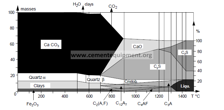
Evaporation Zone
![]()
![]()
Dehydration Zone
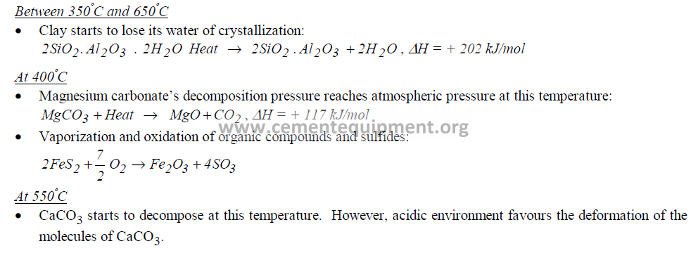
Decarbonation Zone
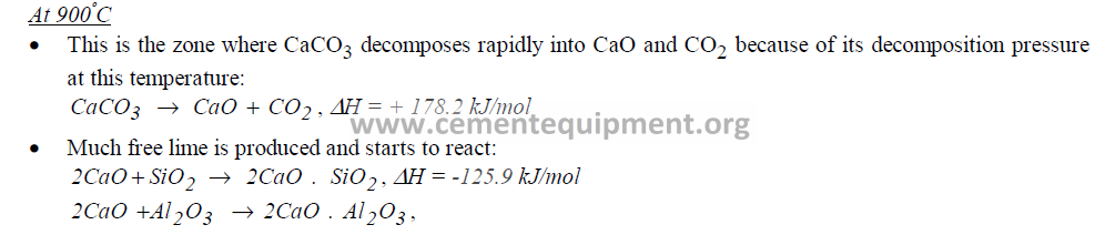

Clinkering Zone

Cooling Zone

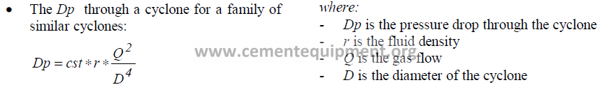
Cyclone
Pressure Drop
Thermal Efficiency

Trapping Efficiency

Calculation of Material Flow

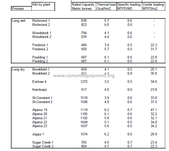
Chains
Guideline


• Chain surface: 19m2/t for oval chains vs. 22-25 m2/t for round chains.
• For small kilns, ratios are always lower than for larger kilns.
• Ratios are higher for dry kiln compared to wet kiln.
• Chainless sections are applied along chain zone aiming to:
– equalize gas temperatures
– serve as a buffer area to equalize varying rates of material transportation
– precipitate kiln dust
– allow for installation of thermocouples
Other Rules of Thumb
• 1500 m of installed chains reduces the exit chain gas temperature by 100oC.
• A properly designed chain system can lower the SHC by 300 kcal/kg ck.
• heat exchange rate: 8.75 kcal/h/m2/C.
• pressure per one meter of chain: 1-2 mm H2O for curtain chain and 2-3 for Gartand chain (note: Garland chains are abandoned due to practical considerations in maintaining hanging pattern).
• For Gartand chain, the thermal effect is 1.5 time higher than curtain chain.
• Wear rate: 80-120 g/t ck for wet kiln and 100-150 for dry kiln.
Cooler
Compartments


• N has to be chosen to allow 1.6 * N in case of push.
• The length of the recuperation zone will be set with an air density between 1.45 Nm3/m2*s (Fuller) and 1.55 (IKN) and a heat consumption 800 kcal/kg and 0.85 Nm3/kgkk for the combustion air.
Cooling zone:
• The cooler loading will be the factor determining the cooling zone length:
– 40 t/m2/daydryprocess (highpressurefans thickbeddepth(60 cm))
– 35t/m2/day wet process (high pressure fans)
– 28 t/m2/day all processes (low pressure fans, thin bed depth (30 cm))
Rules of thumb
• Air velocity above clinker bed: 5 to 7m/s.
• 6 to 10 strokes per minute, cooler stroke length around 5”, clinker speed around 1 to 1.2 m/min.
• Clinker granulometry: passing 0.5mm:<15% , remaining at 25mm<10%.
• Void volume: about 0.4 to 0.5.
• Clinker bulk density: 89 to 120 lb/ft3.
• Grate cooler: 5-10 kWh/ t, target should be below 5 kWh/t w/o vent air fan.
Fans
Recuperation zone
• Maintain the flow during a kiln push: the fan maximum pressure has to be 30% higher than the nominal. At constant flow, 15% of security to absorb the pressure variation. It is also a good security to keep 30% of flow reserve between the peak of the curve and the nominal.
• In the kiln, minimum cooling rate between 1450 and 1300C: 20C/min.
Cooling zone
They should be able to go from 2.5 to 3 Nm3/kg during a push. Their curve should be flatter and their maximum pressure 30% above the functioning point. 20% increase in flow has to keep 15% safety margin on pressure. Minimum is 30 mbar for single-stage cooler.
Rules of thumb
• Grate plate resistance is directly related to the air flow and represents about 15% of total air resistance.
• Basic operating principles:
– Maintain a constant air to clinker ratio
– Maintain a constant bed depth
– Remove all excess cooling (vent) air
• The longer the air/clinker contact time, the cooler the clinker.
• The higher the velocity air, the colder the clinker surface, the higher the heat transfer rate from center to edge of the clinker but the lower the between air and clinker edge.
• Average cooling air flow (Lafarge Corp): 3.7 kg/kg kk, 2.9Nm3/kg kk.
• Average grate loading: 30 mt/m2/d (the older the lower usually).

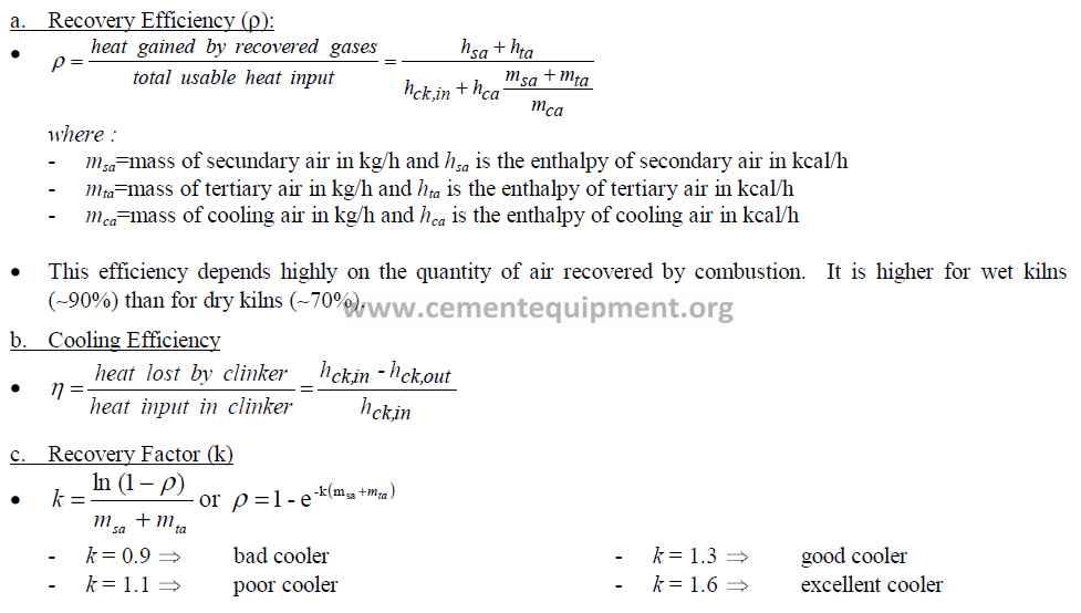
Cooler Efficiency Coefficients

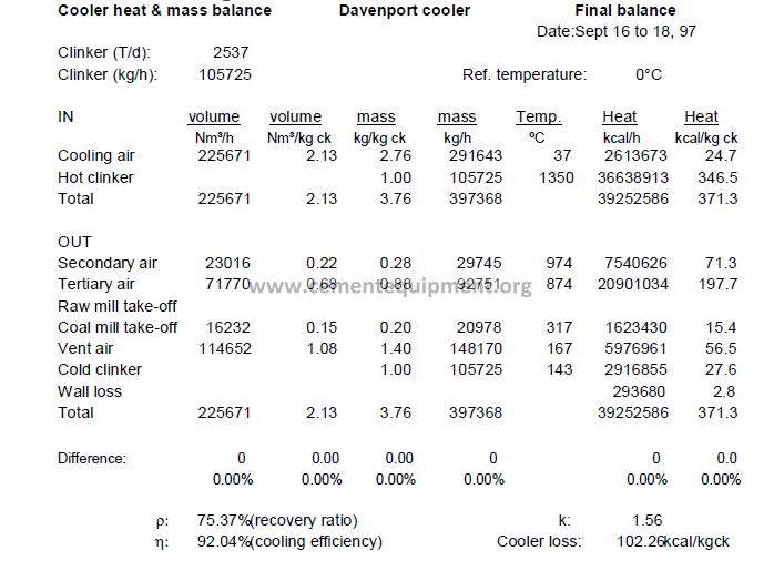
Typical Heat Balance Davenport Cooler

Kiln Heat Balance
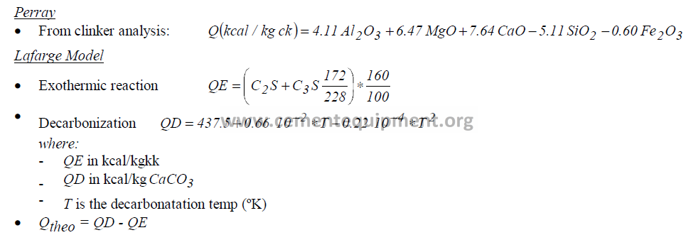
Theoretical Heat for Clinker Formation
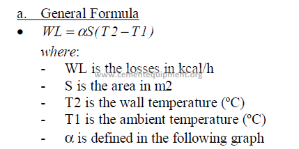
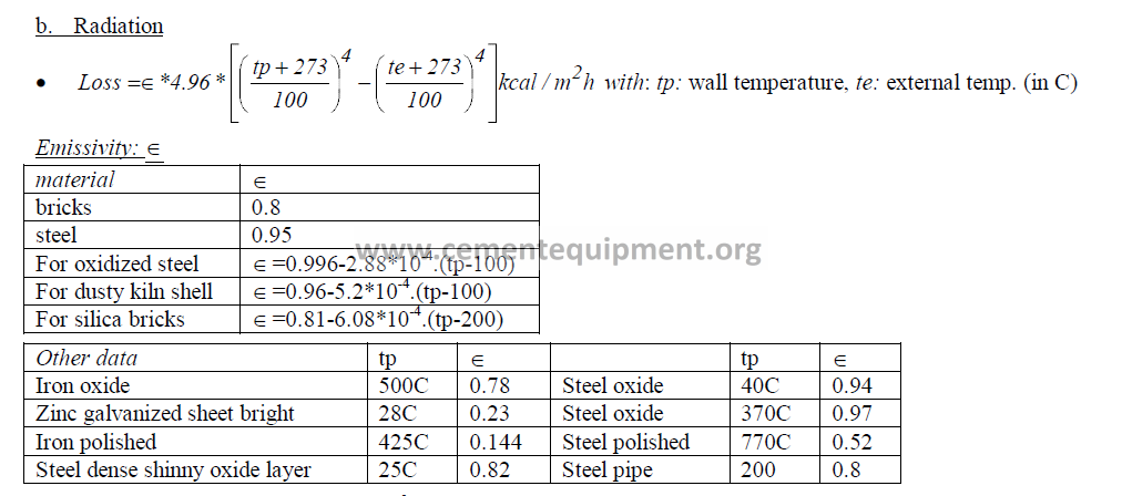
Wall Losses


Kiln Residence Time

Water Spray

Heat Balance Example


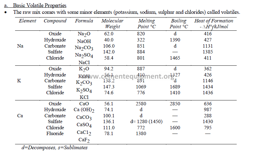
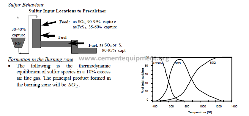
Volatile
Properties of Volatile Elements
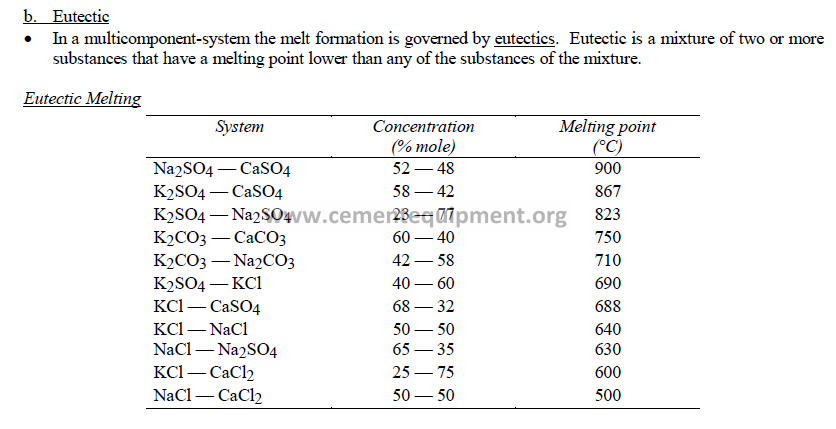


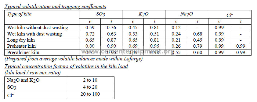
Volatilization Process


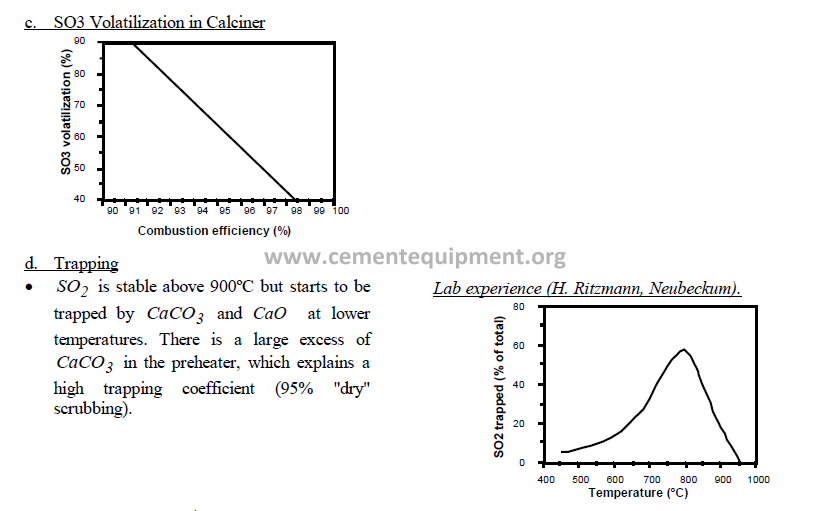

Build-up and Rings
• After condensation and before solidification of the volatiles, the dust particles will be sticky and tend to agglomerate on solid objects: kiln walls, chains or lower cyclones of preheater tower.
• The sulphur build-up usually occurs where the temperature is between 800°C and 1100°C: kiln walls and chains for a long kiln, smoke chamber and lower cyclone for a preheater kiln. In those build-ups, the following sulfates are most commonly found: Arcanite (K2SO4), Anhydrite (CaSO4), Glaserite (K3Na (SO4)2), Ca-Langbeinite (K2Ca2 (SO4)3) and sulfate spurrite (Ca2 (SiO4)3 CaSO4).
• In a long kiln, the build-ups are formed below the internal exchanger. This takes place in the kiln load so the build-ups formed this way are naturally destroyed in the majority of the cases. In small diameter kiln, however, a sulfate ring can appear.
• Chlorine will condense in the 600°C to 700°C zones, that is in the chains for a long kiln.
• Operational difficulties when the concentration of circulating elements in the load material exceeds the following levels (on clinker basis):
– Na2O+K2O = 3–5 %, SO3 =3–5 %, Cl- =1.2–1.6 %
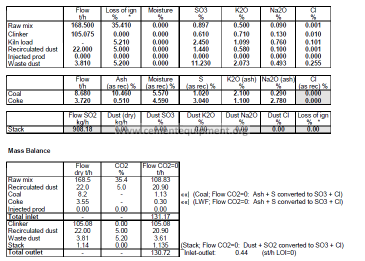
Volatile Balance Example


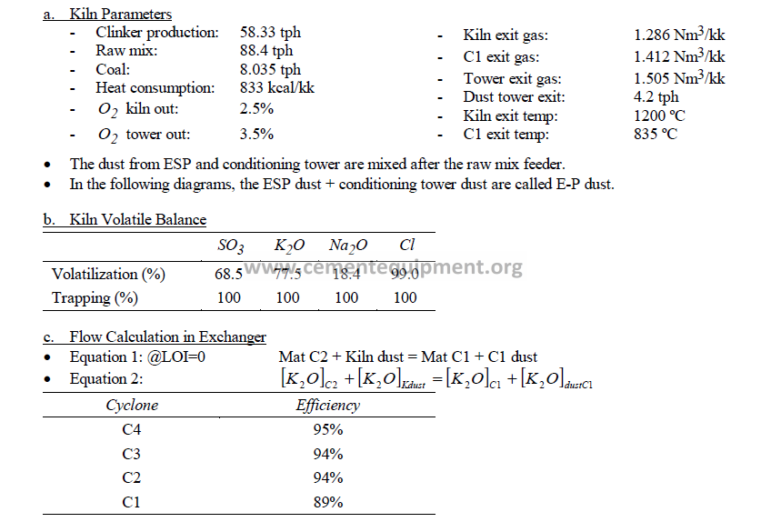
Circulation in Preheater (Port-la-Nouvelle)

Typical Ratios

Clinker Reactivity Study (P. Barriac)
