
Quick engineering answer
Clinker-cooler grate clearance should be evaluated as a repeatable pattern across fixed/moving interfaces, not as one isolated gap. Map clearances, wear, rubbing, leakage and frame geometry across the cooler, then correct the mechanical cause before locally adjusting components or approving the shutdown work.
Inspect only under the cooler OEM and plant isolation procedure.
Record fixed/moving interfaces, aeration elements, seals and transport geometry.
Compare left, center and right clearances at repeatable stations.
Re-measure after repair and verify free movement, sealing and OEM acceptance.
Why grate clearance matters
In reciprocating and moving-floor clinker coolers, the relationship between stationary and moving components affects transport, sealing, aeration and mechanical loading. Excessive or uneven gaps can be evidence of wear, frame movement, sagging, misalignment or damaged grate components. Too little running clearance can create rubbing, heat generation and mechanical loading. The objective is therefore not to chase one universal clearance value; it is to confirm that the complete grate line remains mechanically free, aligned and consistent with the OEM design.
Start with a cold, secured inspection condition
- Follow the cooler OEM and plant lockout/tagout procedure and confirm all hydraulic, electrical and mechanical energy is isolated.
- Allow the cooler to reach the inspection condition required by the manufacturer before entering the housing.
- Remove clinker deposits that prevent reliable visual or dimensional inspection without damaging grate surfaces.
- Use the same reference locations during each shutdown so changes can be trended.
Map fixed and moving grate interfaces
Identify the fixed rows, moving rows or moving transport elements used by the installed cooler. IKN describes its grate as fixed and mobile rows mounted on a moving frame, while modern Polysius designs combine stationary aeration elements with a separate moving clinker-transport system. Because architectures differ, the inspection sheet should first identify the exact cooler zone and component type before any gap is judged.
| Inspection point | What to look for | Diagnostic direction |
|---|---|---|
| Fixed-to-moving interface | Uneven gap, polishing, rubbing marks, clinker wedging | Check wear, frame alignment, support condition and local deformation |
| Aeration element seating | Loose, lifted, cracked or eroded elements | Check fasteners, support surfaces and replacement condition |
| Side seals / labyrinth areas | Wear tracks, open leakage path, clinker ingress | Inspect seal geometry and adjacent structural movement |
| Moving frame path | Contact marks or non-uniform travel clearance | Check frame support, drive synchronization and mechanical obstruction |
| Cooler discharge zone | Heavy local wear, oversize impact or distorted components | Check clinker distribution, crusher condition and impact loading |
Measure a pattern, not one point
Use a repeatable grid of measurement locations across the cooler width and along the clinker travel direction. Record the location, measured clearance, wear condition and whether the reading is taken at a fixed/moving interface, aeration element, side seal or other OEM-defined reference. A single acceptable measurement cannot clear a cooler if neighboring positions show progressive wear or contact.
Compare left, center and right-side measurements. A systematic side-to-side difference may indicate frame skew, support movement or asymmetric wear. A local isolated change is more likely to point toward a damaged element, loose support, local buildup or impact.
Inspect for evidence of frame sag or geometry change
IKN notes that in conventional cooler arrangements, movable-frame sag can cause thrust gaps between movable and fixed rows to grow over time; its Linear Pendulum Support concept was developed to counter this behavior. On any cooler design, increasing gap pattern, repeated edge contact or asymmetric movement should trigger a wider check of the frame, support system, bearings/straps, hydraulic drive geometry and structural fasteners rather than repeated local grate adjustment.
Check aeration plates and sealing surfaces
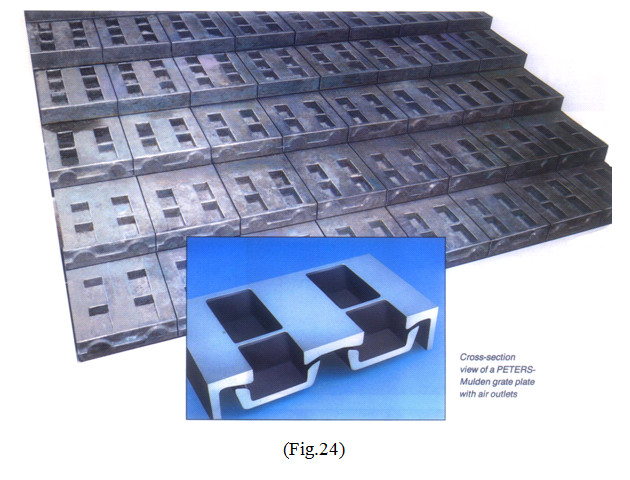
Aeration elements should be inspected for wear, cracking, erosion, looseness, distortion and clinker leakage. Polysius describes modern aeration units as replaceable wear components and highlights sealing features intended to reduce dust escape. If one zone repeatedly loses aeration elements or shows abnormal erosion, investigate air distribution, clinker bed distribution and mechanical support before simply replacing the plate again.
Use clinker leakage as a diagnostic clue
Unexpected clinker below or around the grate can reveal more than a housekeeping problem. Map where leakage occurs and compare it with gap measurements, worn aeration elements, seals and frame interfaces. Concentrated leakage at one location can support the diagnosis of a local opening or damaged element; widespread change may indicate a broader geometry or wear issue.
Shutdown inspection workflow
- Mark reference stations on the cooler inspection drawing.
- Photograph the grate condition before cleaning where safe and useful.
- Clean only enough to expose interfaces and wear surfaces.
- Measure the OEM-defined clearances at repeatable points.
- Inspect fixed rows, moving rows, aeration plates, seals and fasteners.
- Record rubbing, polishing, cracks, clinker leakage and abnormal wear.
- Check moving-frame/support geometry when gaps vary systematically.
- Compare findings with the previous shutdown and OEM acceptance limits.
- Repair the root mechanical cause before final adjustment.
- Re-measure and document the final condition before closing the cooler.
Acceptance logic
Do not approve the cooler because the average clearance looks reasonable. Acceptance should require that measured values comply with the installed cooler’s OEM criteria, moving components travel freely, no abnormal contact pattern remains, aeration elements are secure, seals/interfaces are serviceable and the final geometry is consistent across the inspected zones. When a local adjustment changes neighboring gaps, re-check the surrounding stations before closure.