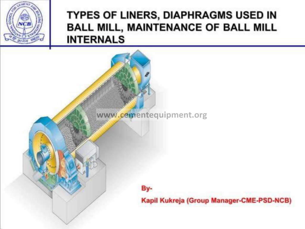
Ball Mill Liners & Diaphragms: Types & Care
The ball mill is the workhorse of cement grinding, and its internal fittings, the liners and the diaphragms, determine the entire grinding economy of the plant. The liners protect the mill shell, transmit the energy of the mill rotation to the grinding media, and shape the motion of the charge, while the diaphragms separate the compartments, control the material flow, retain the grinding media in each compartment and support the mill shell structurally. This article is a complete technical treatment of the types of liners and diaphragms used in a ball mill, together with the maintenance practice that keeps them in service: the lifting and classifying liners that dominate modern mills, the wave and corrugated profiles that shape the charge, the single-wall and double-wall diaphragms, the grate types and their slot sizing, and the inspection, wear measurement, repair and replacement procedures that make up ball mill internal maintenance. Written for mill operators, maintenance engineers, grinding specialists and plant managers, the article follows the logic of a professional maintenance training course, and it treats the mill internals not as passive steel parts but as the active tuning instruments of the grinding process.
The Role of the Liners in the Mill
The liner system of a ball mill has three distinct functions. The first is protection: the liners cover the interior of the mill shell and the mill heads, shielding the shell plate from the impact and abrasion of the grinding media and the material being ground. The shell of a grinding mill is expensive to replace, and the liner is the sacrificial layer that absorbs the wear. The second function is energy transmission: the liners grip the grinding media and lift it with the rotation of the mill, converting the rotational energy of the mill into the kinetic energy of the media charge. The profile of the liner determines how high the charge is lifted and how it falls back, and this directly determines the grinding action.
The third function is the control of the charge motion itself. A liner with a pronounced lifting profile produces a cataracting charge that falls back with high impact, suited to the coarse grinding in the first compartment. A smoother liner produces a cascading charge that rolls and grinds by attrition, suited to the fine grinding in the later compartments. The liner profile is therefore a design variable that the plant selects to match the material, the mill configuration and the target product, and it is one of the most powerful levers available for mill optimisation.
The liner is also a significant cost item. Liner materials, from the traditional high-chromium white iron through the high-strength alloy steels to the newer composites and rubber compounds, span a wide range of price and wear life. The choice of liner material and profile, balanced against the cost and the life, is a major element of the mill’s operating economy, and it is a decision that the plant revisits at every liner change.
Materials of Construction for Liners
The traditional material for ball mill liners is white cast iron, with the chromium content graded from the low-chromium irons of 1 to 2 percent up to the high-chromium irons of 12 to 30 percent. The high-chromium white irons offer excellent abrasion resistance and are the standard for the first-compartment liners where impact and abrasion are most severe. Their hardness, in the range of 500 to 700 HB, gives them a long service life, but their brittleness makes them prone to breakage under very severe impact.
For applications where toughness is required, the alloy steel liners are used, including the manganese steels with their exceptional impact toughness and work-hardening behaviour, and the low-alloy martensitic steels with their balance of hardness and toughness. The steel liners are used where the impact forces are too high for the white irons, or where the liner must tolerate distortion of the shell. The rubber liners, with their steel backing plates and rubber wearing surfaces, are used in the fine-grinding applications where the media sizes are small, offering long life, low noise and reduced mill weight, at the cost of a lower charge-lifting ability.
The composite liners combine a steel body with a wear-resistant insert, usually in the form of a hard metal or ceramic bar cast into the lifting face. The composite designs aim to combine the toughness of the steel with the abrasion resistance of the hard insert, and they are increasingly used in the first compartments of large mills where the media sizes and the impact forces are high. The material selection for a given mill is a balance of wear life, toughness, cost and the risk of breakage, and the maintenance team records the actual wear life achieved in each position to guide the next selection.
Lifting Liners
The lifting liner is the classic first-compartment profile, designed to lift the grinding media to a height from which it falls back onto the material at the toe of the charge, producing the impact that does the coarse grinding. The lifting action is created by the shape of the liner face, which is stepped, winged or ribbed so that it presents a mechanical edge that catches the media and carries it upward as the mill rotates. The height of the lifting edge and the angle of the face determine the release point and the trajectory of the charge.
The lifting liner is characterised by its lift height, expressed as a fraction of the media diameter, and by its face angle, which sets the release point. A liner with a high lift and a steep face produces a high cataracting charge with strong impact, suited to large media and coarse feed. A liner with a lower lift and a flatter face produces a lower charge with more attrition, suited to smaller media and finer feed. The design of the lifting profile is a compromise between the grinding action required and the wear and breakage risks associated with high-energy impact.
In modern practice, the first-compartment lifting liners are often of the composite type, with a hard wear bar in the lifting face and a steel or iron body that can survive the impact of the largest media. The lifting liner is typically fitted in the coarse-grinding compartment of the mill, and its life is limited by the abrasion of the media and the material, with typical life spans measured in thousands of operating hours before the lifting edge is worn away and the liner must be replaced.
Classifying Liners
The classifying liner is the modern development that has transformed the design of the fine-grinding compartment. Its purpose is not only to lift the media but to classify it along the length of the compartment, holding the larger media at the inlet and allowing the smaller media to progress toward the outlet, so that the media size distribution matches the material size distribution at each point along the mill. This classification produces a much more efficient grinding process, with the energy concentrated where it is needed.
The classifying action is created by the profile of the liner face, which is inclined and stepped so that the effective height of the lifting edge varies along the mill. The liners are installed with the higher lifting edges at the inlet end, so that the media is held back and the large media stays near the feed, and with the lower edges toward the outlet, allowing the small media to move forward. The result is a natural size segregation of the media within the compartment, giving a grinding environment that matches the decreasing material size.
The classifying liner is available in several geometric arrangements, including the two-step, three-step and four-step designs, with the number of steps determining the fineness of the classification. The choice of step arrangement is based on the mill length, the compartment length, the media charge and the target product fineness. The classifying liner has become the standard for the second compartment of modern cement mills because it reduces the specific energy consumption, improves the product fineness distribution and reduces the media consumption, and its maintenance, although it is more complex to inspect than the simpler profiles, is well rewarded.
Wave and Corrugated Liners
The wave liner and the corrugated liner are profiles designed to produce a moderate, smooth lifting action with good media grip and low media breakage. The wave liner has a continuous sinusoidal or wavy profile across its face, presenting a series of rounded peaks and valleys that grip the media without the sharp edges of the stepped lifting profile. The corrugated liner is similar, with a regular corrugated pattern of ridges and grooves. Both profiles are used in the later compartments and in mills where a gentle, attrition-dominated grinding action is required.
The advantage of the wave and corrugated profiles is the smoothness of the charge motion. The rounded profile releases the media gradually, producing a cascading charge with a high frequency of low-energy contacts, which is efficient for fine grinding and gentle on the media and the liner itself. The profiles also reduce the noise of the mill and reduce the risk of media breakage compared with the high-lift profiles.
The wave and corrugated liners are used in the fine-grinding compartments of cement mills, in slag mills and in raw mills where the material is ground to a fine product. They are also used in the second compartments of some mills instead of the classifying liner, where the plant judges that the simpler profile, with its lower cost and simpler maintenance, is more appropriate for the specific application.
Other Liner Types
Beyond the four main families, the ball mill uses several special liner types. The smooth or plain liners, with a flat face and minimal lifting action, are used where the charge must slide rather than cascade, and they are found in the fine compartments and in some overflow discharge mills. The shell liners with an axial slope, known as the step liners, assist the material and media flow along the mill. The head liners and the cone liners, fitted to the mill heads and the discharge cones, protect these parts and guide the discharge flow.
The lifter bars, also known as the shell lifters, are the narrow lifting elements fitted to the shell liners in the mills that use the two-piece liner systems, where a flat base liner is fitted with a separate lifter bar. The lifter bars are the replaceable wear elements, and their height and shape set the lifting action. The advantage of the two-piece system is that the lifter bars can be replaced without replacing the whole liner, reducing the maintenance cost.
The material of the lifters and the special liners follows the same selection logic as the main liners, and the wear of the lifters is the principal driver of the liner change interval in the mills that use them. The maintenance team must understand which elements are the wear-limiting ones in each design, and must schedule the inspections accordingly.
Liner Fixing and Attachment
The liners are attached to the mill shell either by bolts or by boltless fixing systems. The bolted systems use a bolt passing through the liner and the shell, with a nut and a sealing washer on the outside of the shell, and the liner is positioned and locked by the bolt. The boltless systems use a T-shaped or wedge-shaped locking element fitted between the liner and the shell, or a key-and-groove arrangement, eliminating the through-bolts and the associated shell holes.
The bolted systems have the advantage of a positive, verifiable fixing, but they require holes in the shell, which are a source of leakage, stress concentration and corrosion, and the bolt heads are exposed to the grinding atmosphere inside the mill. The boltless systems eliminate these problems but rely on the frictional grip and the interlocking of the liner elements, and they require the liner to be installed in the correct sequence with the correct torque and the correct sealing.
The integrity of the liner fixing is a critical maintenance concern. A loose liner moves under the charge, hammers against the shell, and can break or wear the shell. The inspection of the liner fixing, including the checking of the bolt torque, the detection of leaks and the examination of the locking elements, is a standard part of the mill internal inspection, and the re-torquing of the bolts and the replacement of the damaged fixing elements is a scheduled task.
The Role of the Diaphragm
The diaphragm, also called the mill partition or the intermediate diaphragm, is the internal wall that divides the mill into compartments. In the two-compartment mills that are the standard for cement grinding, the diaphragm separates the first compartment, where the coarse grinding with the large media takes place, from the second compartment, where the fine grinding with the small media takes place. The diaphragm performs three functions: it supports the mill shell, it retains the grinding media in each compartment, and it controls the material flow between the compartments.
The structural function is important. The diaphragm is a radial wall inside the mill, and it contributes to the stiffness of the mill shell, resisting the ovalising forces that act on the shell. The diaphragm is therefore not only a process component but also a mechanical one, and its bolts, its segments and its connection to the shell must be maintained to keep the mill structurally sound.
The process function is the separation of the grinding actions. The large media in the first compartment cannot be allowed to pass into the second compartment, where it would destroy the fine-grinding action and the classifying liner, so the diaphragm must have gaps or slots that pass the material but retain the media. The correct slot size, the correct open area and the correct position of the slots are the parameters that determine how well the diaphragm performs this separation, and they are the subject of careful design and maintenance.
Single-Wall and Double-Wall Diaphragms
The single-wall diaphragm is the simplest design: a single perforated plate, or a ring of perforated segments, bolted to the mill shell, with the slots passing the material from one compartment to the next. The single-wall design is compact and simple, but it has the disadvantage that the material passes straight through, so that the residence time in each compartment is less controlled and the material can short-circuit through the slots.
The double-wall diaphragm, also called the double-deck or intermediate diaphragm with the material lifter, consists of two parallel walls with a space between them. The material passing through the slots of the first wall enters the space, is lifted by the scoops or lifters in the space, and is delivered through the openings of the second wall at a position determined by the design. The double-wall design gives a positive transport of the material, prevents the short-circuiting, and allows the material level in the two compartments to be controlled independently.
The double-wall diaphragm is the standard for the intermediate position in modern multi-compartment mills, because its positive transport and its separation of the compartment atmospheres improve the grinding efficiency and the fineness control. Its maintenance is more complex than the single-wall design, because it contains more moving and wearing parts, but the performance benefit justifies the complexity.
Grate Types and the Discharge Diaphragm
The discharge diaphragm, also called the outlet diaphragm, is the grate at the discharge end of the mill that separates the material from the media and allows the ground material to leave the mill. The discharge grate is a wall with a pattern of slots sized to pass the finished product but to retain the smallest media, and the material that passes through the slots falls into the discharge housing and is conveyed to the separator or the conveying system.
The discharge grate is fitted with an outer ring of discharge lifting paddles or scoops that lift the material from the mill and deliver it to the discharge outlet, and with the discharge screen that holds the media back. The discharge diaphragm is subject to the highest wear of all the mill internals, because the material and the media pass over it continuously, and the slot edges are abraded by the media impact. The wear of the slot edges increases the effective slot width, which in turn allows the smaller media to pass into the discharge, contaminating the product and increasing the media consumption.
The grate types used in the discharge position include the segmental grates, made of several interchangeable segments bolted to the diaphragm ring, and the one-piece grates used in the smaller mills. The segmental design allows the worn segments to be replaced without dismantling the whole diaphragm, reducing the maintenance time. The maintenance of the discharge grate, including the inspection of the slot widths, the detection of the worn and broken segments and the replacement of the damaged parts, is one of the most frequent and most important maintenance tasks in the mill.
Slot Sizing in the Diaphragms
The slot size of the diaphragm is the primary parameter that controls the material flow and the media retention. The slots must be wide enough to pass the largest material particle that should leave the compartment, but narrow enough to retain the smallest media in the compartment. The rule of thumb is that the slot width must be smaller than the minimum media diameter retained, with a margin that accounts for the wear of the slot edges over the life of the diaphragm.
The slot size also determines the open area of the diaphragm, which sets the resistance to the material flow and the pressure drop across the diaphragm. A diaphragm with a small open area restricts the flow, raises the material level in the upstream compartment and can overfill the mill. A diaphragm with a large open area passes the material freely but may allow oversized material into the next compartment, upsetting the grinding balance.
The slot pattern, including the orientation of the slots, the number of slots and their distribution around the diaphragm, is designed to give a uniform radial distribution of the material flow. The slots are typically radial or circumferential, and the design balances the flow distribution against the structural strength of the diaphragm. The maintenance team measures the slot widths at every inspection, trends the wear, and replaces the diaphragm when the slot widths approach the point where the media would pass.
Media Retention and the Screen Elements
The media retention function of the diaphragms is critical to the mill’s operation and to the protection of the downstream equipment. If the media passes through the intermediate diaphragm into the second compartment, it mixes with the fine media, disrupts the grinding action and can damage the classifying liner. If the media passes through the discharge grate, it contaminates the product and can damage the separator, the conveyor and the bucket elevator.
The intermediate diaphragms are fitted with a media retention screen or with the slot design that retains the media, and the discharge diaphragm is fitted with a discharge screen that catches the media that reaches the outlet. The screens are made of wear-resistant steel and are themselves subject to wear and to damage from the media impact, and their condition is a maintenance-critical item.
The failure of the media retention function is one of the most common mill problems, and its detection depends on the operator’s attention: the sound of media passing into the discharge, the presence of media in the bucket elevator, the rising power draw and the deteriorating product quality all signal a media breakthrough. The maintenance response is to stop the mill, inspect the screens and the slots, and replace the damaged elements before the breakthrough damages the downstream equipment.
The Mill Shell and Head Liners
In addition to the shell liners and the diaphragms, the mill is fitted with the head liners on the inlet and discharge heads. The head liners protect the mill heads, which are the cast or fabricated end walls of the mill, from the wear of the charge, and they shape the flow of the material and the media into and out of the mill. The inlet head liner is often fitted with a lifting or spiraling profile that assists the entry of the feed into the mill body, and the discharge head liner guides the material toward the discharge outlet.
The head liners are subject to the abrasive wear of the material and the media, and they are replaced at the same maintenance interval as the shell liners. The inspection of the head liners includes the checking of the wear, the detection of the loose or broken segments and the verification of the fixing, and the replacement of the head liners is a standard part of the mill relining job.
The mill heads themselves are also inspected at the relining, because the heads are exposed to the atmosphere inside the mill and to the load of the charge, and they develop fatigue cracks and corrosion over time. The ultrasonic testing of the heads and the shell at the relining, and the repair of the detected defects, is the maintenance that protects the mill’s structural integrity.
Ball Charge and Liner Interaction
The liner and the media charge interact continuously, and the health of each depends on the other. A liner that is worn down to a smooth profile lifts the charge less effectively, the charge slides rather than cascades, and the grinding efficiency falls while the energy consumption remains the same. A charge that has lost its correct size distribution, with too many small balls and too few large ones, cannot be lifted effectively by the liner and grinds inefficiently.
The plant manages this interaction through the regular measurement of the charge level, the size distribution and the liner wear. The charge level is measured with the standard method of stopping the mill, opening a hatch and measuring the height of the charge above the lowest point, and the size distribution is determined by sampling the media during a shutdown. The liner wear is measured by the depth gauges or by the measurement of the remaining thickness of the liner at the inspection.
The grinding media consumption and the liner wear are two sides of the same economy. The plant monitors the specific media consumption and the specific liner consumption in grams per tonne of product, and it uses the trends to optimise the media grade, the liner profile and the change intervals. A mill that is grinding inefficiently shows up in both the energy consumption and the wear rates, and the maintenance team must consider both together.
Inspection of the Mill Internals
The inspection of the mill internals is the heart of the maintenance program, and it takes place at every scheduled mill stop. The inspection begins with the safety isolation of the mill, the locking of the drive, the ventilation of the mill interior and the gas testing for the confined space entry, and it proceeds with the visual and instrumented examination of the liners, the diaphragms, the charge and the shell.
The visual inspection of the liners checks the profile wear, the presence of the lifting edges, the condition of the bolts and the fixing elements, and the presence of any cracks, breakage or missing segments. The measurement of the remaining liner thickness, using a caliper or an ultrasonic gauge where the access allows, quantifies the wear and predicts the remaining life. The inspection of the diaphragms checks the slot widths, the condition of the screens, the wear of the grate segments and the integrity of the diaphragm-to-shell connection.
The inspection results are recorded in a standard format, with the measurements of the representative liner positions, the slot widths and the charge condition, and the records are compared with the previous inspections to establish the wear trends. The trends allow the maintenance team to predict the liner life, to plan the relining stop in advance and to order the spares in time, converting the mill internal maintenance from a reactive activity into a planned one.
Wear Measurement and Life Prediction
The accurate measurement of the liner wear is the basis of the life prediction and the planning of the relining. The wear is measured at a defined set of positions, typically at the inlet, the middle and the outlet of each compartment, and at several positions around the circumference. The measured remaining thickness, compared with the original thickness, gives the wear rate in millimetres per operating hour, and the extrapolation of the trend gives the predicted life to the minimum allowable thickness.
The minimum allowable thickness is set by the structural strength of the liner and by the risk of penetrating the shell. The liner must retain sufficient thickness to withstand the impact of the media without cracking, and to protect the shell from the media contact. The maintenance team sets the replacement limit from the design data and the operating experience, and the liners are replaced before they reach the limit to avoid the risk of a liner failure that damages the shell.
The wear of the diaphragms and the screens is measured by the same approach, with the slot widths and the thicknesses recorded at the inspection. The diaphragms are replaced when the slot widths approach the media diameter, and the screens are replaced when the wear reduces their strength or when the breakthrough risk becomes unacceptable. The life prediction for all the internal parts is the basis of the mill’s maintenance plan and the spare parts inventory.
The Relining Procedure
The relining of the mill is the major maintenance event, and its quality determines the next campaign of operation. The procedure is well established. The mill is stopped, isolated and cooled, the media charge is removed either by hand or by the mechanical charger, the worn liners are removed, the shell is inspected and cleaned, and the new liners are installed in the correct sequence with the correct torque and the correct alignment.
The installation sequence is critical, especially for the boltless liner systems where each element interlocks with its neighbours and the fixing depends on the order of assembly. The liners must be installed with the correct circumferential and axial alignment, with the lifting profiles oriented in the direction of rotation, and with the fixing elements correctly tensioned. The head liners and the diaphragms are installed with the same care, and the diaphragm bolts and the shell bolts are torqued to the specified values.
The relining is a major logistic operation, with the materials handling, the crane work, the confined space work and the quality control all coordinated. The plant that plans the relining carefully, with the spares pre-positioned, the procedures documented and the crews trained, completes the job in the minimum time and starts the mill with the confidence that the internals will serve the full campaign. The plant that treats the relining casually pays for it in premature wear and failures.
Relining and Start-Up Checks
After the relining, the mill is prepared for start-up with a defined set of checks. The mill is first turned slowly with the inching drive to verify that the internals are correctly installed and that nothing is loose or obstructing the motion, and the mill is then charged with the correct volume and size distribution of media. The first operational checks after the start-up include the power draw, the mill sound, the material flow and the product quality, which confirm that the new internals are performing as intended.
The early operating period after a relining is a run-in period, during which the new liners and the new media bed into each other and the wear surfaces develop their working profile. The mill is run at the normal conditions, but the operator watches the power draw and the product quality more closely, and the mill is stopped briefly after the first days of operation for a short inspection of the internals and the re-torquing of the bolts that may have settled.
The documentation of the start-up, including the power draw, the charge level and the initial wear measurements, provides the baseline for the next campaign. The comparison of the campaigns, using the specific energy, the specific media consumption and the liner life, allows the plant to evaluate the liner selection and the operating strategy, and to improve both at the next relining.
Common Failure Modes of the Internals
The mill internals fail in a characteristic set of modes. The liners fail by abrasion of the lifting edges, by cracking under the impact of the media, by breakage of the brittle white-iron segments, by loosening of the bolts and by corrosion of the shell behind a failed liner. The diaphragms fail by wear of the slots and the screens, by breakage of the grate segments, by fatigue of the diaphragm-to-shell connection and by the jamming of the diaphragm openings with oversized material.
The detection of the developing failures relies on the monitoring signals and the inspections. A rising specific energy with a falling throughput indicates the worn liner profile or the degraded charge. A rising discharge temperature and a deteriorating fineness indicate the media breakthrough or the diaphragm failure. A metallic noise from the mill interior indicates the loose liner or the media hitting the shell, and a rising vibration indicates the mechanical imbalance or the loose internals.
The prevention of the failures follows from the disciplined maintenance: the scheduled inspections, the measured wear trends, the planned relining and the attention to the operating signals. The plant that prevents the failures protects not only the internals themselves but the mill shell, the drive and the downstream equipment, all of which are damaged when an internal part fails in service.
Key Parameters of the Internals and Their Ranges
The management of the mill internals is supported by a small set of measurable parameters. The table below summarises the typical values for a modern cement ball mill and the meaning of a deviation from the normal range.
| Parameter | Typical normal range | Meaning if below range | Meaning if above range |
|---|---|---|---|
| Liner remaining thickness | Design minimum to original | Risk of shell penetration | New liner, full life remaining |
| Diaphragm slot width | Below minimum media diameter | – | Media passes into next compartment |
| Charge level, first compartment | 28 – 32 percent of volume | Low lifting efficiency | Overfilled; power overload |
| Charge level, second compartment | 26 – 30 percent of volume | Low grinding action | Overfilled; risk of diaphragm damage |
| Specific energy consumption | 28 – 35 kWh per tonne cement | Efficient grinding | Worn internals or degraded charge |
| Media consumption | 300 – 600 g per tonne cement | – | Worn liners, wrong charge or breakthrough |
| Mill sound level | Consistent grinding note | Overloaded or empty mill | Dangerously loud; impact on shell |
The value of the table is that it converts the qualitative description of the internals into quantitative limits that the operator and the maintenance engineer can measure, trend and act on.
Optimisation of the Internals
The selection and the operation of the mill internals is an optimisation problem, and the modern plant approaches it systematically. The starting point is the characterisation of the material: the feed size, the grindability, the moisture and the product target. The feed size distribution determines the required media charge and the first-compartment liner profile, and the product fineness determines the second-compartment liner and the diaphragm design.
The optimisation continues with the tuning of the media charge, the liner profile and the diaphragm slotting in response to the operating results. The plant measures the product fineness, the specific energy and the mill throughput, and it adjusts the internals at the relining to close the gap to the target. The modern mills use the classifying liners and the double-wall diaphragms as standard because the measured performance benefit justifies the cost, and the trend is toward the further refinement of both.
The optimisation is supported by the mill simulation tools and by the measurement campaigns, including the material sampling along the mill length and the media size analysis. The plant that treats the mill internals as a tuning instrument, rather than as a set of wear parts, extracts the maximum grinding efficiency from the mill, and the improvement in specific energy and product quality is the direct reward.
The Future of Mill Internals
The future of the mill internals is being shaped by the materials science and the digitalisation. The liner materials are improving toward higher hardness with better toughness, reducing the breakage risk and extending the life, and the composite liners with the ceramic inserts are becoming the standard in the high-impact positions. The rubber and composite materials are extending into the coarser applications, reducing the mill weight and the noise.
The digitalisation brings the condition monitoring of the internals. The wear of the liners is increasingly measured with the laser scanners that profile the liner surface during the inspection, and the charge level and the liner condition are inferred from the mill’s acoustic and vibration signatures during operation. The digital twin of the mill predicts the wear of the internals from the operating data, allowing the relining to be planned on the basis of the predicted condition.
The outlook is for mills that run longer between the relinings, with the internals that wear more predictably and that are replaced at the optimal time. The training of the maintenance and the operating staff remains the essential ingredient, because the best liner and the best diaphragm are still only as good as the people who select, install and maintain them.
Frequently Asked Questions
What are the main types of liners used in a ball mill?
The main types are the lifting liners for the coarse grinding compartment, the classifying liners for the fine grinding compartment, and the wave and corrugated liners for the gentle attrition grinding. Each profile shapes the charge motion and is selected to match the grinding duty.
What is a classifying liner and why is it used?
A classifying liner has an inclined, stepped profile that holds the large media at the inlet and allows the small media to progress toward the outlet, matching the media size to the material size along the compartment. It reduces the specific energy consumption and improves the product quality.
What is the difference between a single-wall and a double-wall diaphragm?
The single-wall diaphragm is a simple perforated wall, while the double-wall diaphragm has two walls with a space and lifters between them that positively transport the material. The double-wall design prevents short-circuiting and gives independent control of the compartment material levels.
How is the diaphragm slot size selected?
The slot width must be smaller than the minimum media diameter retained in the compartment, with a margin for the wear of the slot edges over the diaphragm life. The open area is sized to give the correct material flow and the correct material level in the compartment.
How is liner wear measured and the life predicted?
Liner wear is measured as the remaining thickness at defined positions using calipers or ultrasonic gauges. The wear rate in millimetres per hour is calculated from the inspection records, and the life is predicted by extrapolating the trend to the minimum allowable thickness.
What are the signs that the mill internals need attention?
A rising specific energy with a falling throughput indicates worn liners, a rising discharge temperature and deteriorating fineness indicate media breakthrough or diaphragm failure, a metallic noise indicates a loose liner, and a rising vibration indicates loose internals or mechanical imbalance.
Summary
The ball mill internals, the liners and the diaphragms, are the active tuning instruments of the grinding process, and their selection, installation and maintenance determine the mill’s grinding efficiency, product quality and operating economy. This article has covered the full scope of the internal design and maintenance: the three functions of the liners, the lifting, classifying, wave and corrugated profiles and their materials, the single-wall and double-wall diaphragms, the grate types and the slot sizing, the media retention screens, the inspection and wear measurement regimes, the relining procedure and the start-up checks, the common failure modes and their prevention, and the optimisation of the internals against the material and the product targets. The maintenance discipline described here, the regular inspection, the measured wear trends, the planned relining and the attention to the operating signals, is what protects the mill shell, the drive and the downstream equipment, and what keeps the specific energy and the wear rates at their economic minimum. The future of the internals lies in the better materials and the digitalised condition monitoring, but the fundamental requirement remains the trained and disciplined maintenance team. The plant that masters the liners and the diaphragms, that selects them for the duty, that installs them correctly and that maintains them on a planned cycle, will grind the cement at the lowest cost and the highest quality, and it will keep its ball mill as the reliable workhorse that the cement industry depends on.
Get this cement file + the full 931-file package
$249.99 — one-time purchase, instant download, lifetime access
This file is part of the Complete Cement Technical Package (931 files) available from cementequipment.org. Respective rights holders; library copy for the licensed single user.