Contents
To download the below and all other Useful Books and calculations Excel sheets please click here
To download the below and all other Useful Books and calculations Excel sheets please click here
Using lead wire as an aid to adjusting roller skew
David asks
Is there any value in using lead wire to measure between the tire and roller? If so what is the procedure and results obtained.
Well, there is. First off this is a very dangerous practice. My first manager when I started this career almost 40 years ago, crushed his hand when it was accidentally drawn through the pinch point of a very large roller. Naturally he was maimed for life. We do not recommend the use of lead wire testing for this reason and also because interpreting the results is not easy and requires skill and experience. There are safer and more effective methods that can be used to establish roller alignment.
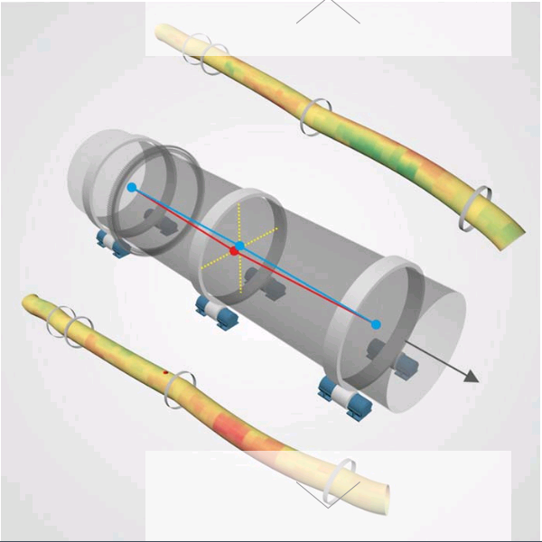
When a length of wire placed across the full width of the roller is allowed to pass through the pinch point it flattens out according to the pressure the tire exerts on it. If this pressure is not uniform, one side to the other, the width of the wire will vary; the higher the pressure the wider and thinner it gets. The variation in pressure can be from;
- roller or tyre surfaces not being flat or cylindrical,
- the roller not sitting on the correct slope,
- the effect of tire wobble (axial run-out), which is always present in varying degrees.
- the effect of shell bends in the vicinity of the tire
- the effect of roller skew
If the rollers and tires are new or newly refurbished by grinding, 1 of the 5 causes is eliminated. Roller shaft slopes can be measured if done carefully, eliminating the 2nd possible cause. The practice then calls for the circumference of the shell to be evenly divided into, say 60 or 45º segments. As each of the 6 or 8 segment “points” cross the roller a wire imprint is collected. The variation in wire width, side to side, one to the next, is due to tire wobble. This takes care of source #3. When the overall average width of each flattened wire varies around the circumference it is the result of a shell bend. That takes care of cause #4. That leaves only skew, which is then seen as a difference of the average wire width one side to the other.
Sounds reasonable but you can now appreciate there are all these factors to eliminate or isolate before you can make sense of it. Additionally there are limitations. For example roller slopes are rarely “spot on” within the usual 0.002”/ft tolerance. Measuring to that accuracy is not easy and in many cases correcting for a bad slope is even more difficult. A bad roller slope also changes the average lead wire width, one side to the other, which then needs to be segregated in order to establish roller skew. Then too how do you evaluate average widths (or thicknesses for that
matter) either in whole or one side to the other?
This description is not exactly a procedure but it does give a gist of what’s involved. I suggest there is a far safer and easier way to proceed.
Posted by Walter Gebhart