Contents
click here to download Holcim , , Lafarge , Most importnant manuals , most important excel sheets
click here to download Holcim , , Lafarge , Most importnant manuals , most important excel sheets
EVERYTHING YOU NEED TO KNOW ABOUT CEMENT KILN FLAME
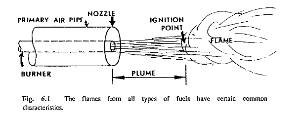
To an untrained eye, all flames in the burning zone of a rotary kiln appear more or less the same. As shown in Fig. 6.1, there is a short plume of air and fuel emanating from the nozzle, then at the end of the plume the fuel ignites and forms the flame. Flames vary considerably in length, shape, color, direction, and point of ignition. With time the novice learns to recognize these characteristics, their effect on kiln efficiency, and how to control them. Such terms as short, long, lazy, snappy, cold flame, and hot flame, the terms used to describe the different shapes and colors of flames, take on a real meaning and soon become commonplace in the language of the kiln operator.
The burner end of a kiln is equipped with a port through which the operator can view the burning zone. Because of the brilliancy of the incandescent fuel and gas, it is necessary to look through a special colored glass to protect the operator’s eyes. When observing the flame, the operator must judge the point of ignition of the fuel, length, direction, and shape of the flame, and the color of the flame, the color being a good indication of flame temperature.
FLAME CHARACTERISTICS
Under stable operating conditions, no changes to the burner assembly or position are normally made unless hot kiln shell conditions make such an adjustment necessary. Therefore, the flame characteristics should theorctically remain unchanged. This, however, is not the case, because flame shape is influenced by many factors such as I:D. fan speed, secondary air temperature, primary air pressure and temperature, as well as changing conditions in the burning zone itself.
The factors that influence these characteristics can be subdivided into two groups. In the first group are the variables over which a kiln operator has little or no control. Some of these variables are impossible to change because they are an integral part of the kiln itself. Those that could possibly be adjusted, require either the help of a third party or a kiln shutdown. The following listed elements can be included in this group:
Group I
Diameter of primary air nozzle
Orifice size of fuel burner
Diameter of the kiln
Design of the burner
Heat value of the fuel
LENGTH OF THE FLAME
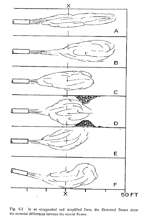
When considering the length of a flame, one must make a clear distinction between two aspects of flame length. Flame length can be referred to as the distance between the nozzle of the burner and the end of the flame, or it can be expressed as the distance between the point where ignition of the fuel starts and where the reaction process of fuel combustion ends, that is, the length of the ignited part of the flame. The difference between these two concepts is often overlooked, but it is important to an understanding of kiln operation. Fig. 6.2 shows clearly the difference between these two measurements. Comparing the two flames A and B, it is seen that the distance between the nozzle of the burner and the end of the flame, 44 ft, is identical on both flames. If the flame length is considered as the ignited part of the flame only, then flame A is 40ft long and flame B is 28 ft. In this book, the terms total flame length and ignited flame length will be used to distinguish the two measurements.
The variables having the greatest influence on flame length are the percentage of combustion air present and the velocity of the fuel-air mixture at the tip of the burner.
It was seen in the previous section on combustion how a fuel, when introduced into the kiln, must combine with oxygen to start the chemical reaction of combustion. In other words, air which contains the oxygen, and fuel have to come into contact with each other to make the fuel bum. A lack of air can cause the flame to become too long, as the fuel then has to search for oxygen further back in the kiln.
Burner-tip velocity is the primary influence on flame configuration when coal and/or coke are fired. Unfortunately, direct-fired kilns most often demand a burner orifice size that is not to the best advantage of good flame control. On such systems; the burner size is more often governed by the coal mill’s minimum air evacuation requirements and coal mill fan static pressure limitations. Flame control, unfortunately, is of secondary priority on such systems. Recently new, more sophisticated coal burner designs have come into use to eliminate some of the shortcomings of direct-fired systems bu! they still present problems in flame-control capability. It is known that a large percentage of indirect-fired kilns, particularly in Europe, operate with tip velocities of between 70-83 m/s (14,000–16,500 ft/min) and show exceptionally good flame patterns. However, direct-fired kilns more often are forced, by system design, to operate with velocities of between 45-66 m/s (9,000–13,000 ft/min) which mostly deliver a relatively lazy swirling flame. Many operators on such direct-fired kilns have unsuccessfully attempted to reduce the burner orifice size (i.e., to increase the tip velocity) and experienced coal evacuation problems from the mill. In other cases, the combination of higher tip velocity and relatively cold primary air have caused unstable and delayed ignition points in the flame. Coal burner designs on direct-fired kilns must be viewed as a compromise solution and is one area that leaves a lot of room for improvements.
Operators should be told by the engineering department what the typical tip velocity is on their kiln under various primary air pressures. As a rule of thumb, it takes a minimum of 35-m/s (7,000-ft!min) velocity in circular pipes to keep finely ground coal particles in suspension. Below this minimum velocity, coal could settle in the pipe and form pockets that could lead to dangerous backfires and/or explosions. Consult with the plant engineer about the minimum permissible, safe primary air pressure and once this level is established, never introduce coal into the system unless you are absolutely sure that the air velocity and pressure are above this minimum permissible level.
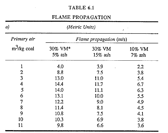
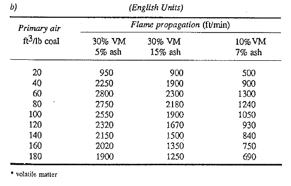
FLAME PROPAGATION SPEED
For coal-fired kilns, the primary air velocity should be at least twice as high as the flame propagation speed to prevent flashbacks of the flame. Flame propagation is usually considerably lower ti1an the velocity needed to convey coal dust by means of primary air into the kiln. Therefore, the minimum velocity necessary to convey coal without settling in ducts takes precedence over flame propagation speed when setting air-flow rates or designing new burners.
W.Ruhland in his investigation of flames, found that a decrease in nozzle diameter will at firSt give a shorter flame, but further decreases in diameter could lead to longer He also found that no change in flame length will take place when the ratio between total combustion air and fuel introduced into the kiln remains constant From this it can be concluded that the flame length is maintained unchanged when the percent oxygen in the exit gases remains the same. In other words, each time the fuel rate is changed, the rate of air going to the kiln should also be changed in order to maintain the same flame length.
The total mass of combustion air entering the kiln is the sum of the primary air, the secondary air, and t11e so-called parasite air which enters the kiln through leaks at the kiln discharge and burner hood. Because the operator has no control over the last air flow (unless he forgets to close one of the large doors of the burner hood), we shall consider only the first two mass flows.
The amount of total combustion air entering the kiln is governed mainly by the speed of the induced draft fan (usually called the I.D. fan). If the fan speed is increased with the fuel rate constant, more combustion air enters the kiln. Conversely, a decrease in I .D. fan speed will result in a decrease in total combustion air entering the kiln. the operator has at his disposal a quick indication with the kiln exit gas oxygen analyzer to determine if the flame theoretically is getting longer or shorter. Lack of combustion air in the kiln is indicated when the oxygen analyzer reading approaches zero and the carbon monoxide combustible instrument shows that carbon monoxide is present in the kiln exit gases.
To explain this effect on flame length consider several examples.
Case 1: Oxygen reading is 2.0%, I.D. fan speed is increased such that the oxygen reaches a value of 4.0%. Result total flame has been lengthened.
Case 2: Oxygen reading is 2.0%, I.D. fan speed is decreased such that oxygen decreases to a value of 0.7%. Result: total flame length has been shortened.
Case 3: Oxygen reading is 0.7%, I.D. fan speed is decreased such that the oxygen obtains a value of 0.1% and a small amount of CO is also indicated. Result: total flame has been lengtlhened.
Case 4: Oxygen reading is 0.1% and combustibles are showing.
I.D. fan speed is increased such that the oxygen increases to 0.7% and no more combustibles are indicated. Result: total flame has been shortened.
From these examples it becomes clear that it is not possible to state simply that an increase in air flow will result in a lengthening of the flame or a decrease will shorten the flame, but that the resulting changes are dependent on the percent oxygen present before the changes in air-flow rates are made.
The total flame length could become infinitely long under the condition of an extreme lack of air. As a matter of fact the fuel could travel the entire length of the kiln without igniting because not enough air is present in the kiln itself. Upon entering the dust collector at the kiln rear where plenty of air is available, the fuel could explode if the temperature is high enough to ignite the fuel. One can easily visualize the results of such a disastrous occurrence.
A word of caution must be expressed at this point. Considering how flame length can be changed by changes in the I.D. fan speed, and knowing the desirability of maintaining the flame length constant, could lead one to the conclusion that the !.D. fan speed should be proportionally changed whenever a change in the fuel rate is carried out. Later on in this book, the pitfalls of such an approach because of its effect on back-end temperature and overall kiln operation in general will be pointed out. One must at all times correlate the different control functions together for the entire kiln operation and take the approaches that will be the most beneficial for stability of kiln operation. For example, maintaining the oxygen content at a fairly constant level while varying the kiln speed is one technique of kiln burning that is not recommended for prolonged stable kiln operation.
In the technique of kiln burning stressed in this handbook, the operator gives special attention to the burning zone temperature and back-end temperature, at the same time maintaining the oxygen content in the kiln exit gases within a range of not less than 0.7% and not more than 3.5%. This “floating” control of the oxygen results in changes of the total flame length. Experience has shown that the flame length changes are of minor magnitude when the oxygen level is controlled within this range, and far more benefits can be derived in operating stability than when the oxygen would be strictly controlled at a constant level.
IGNITION OF THE FUEL
The initial ignition (start of combustion) of the fuel is primarily depen dent on sufficient heat to’ignite the fuel and on sufficient air to obtain combustion of the fuel. A deficiency in either one of the two in the area where the fuel leaves the burner and enters the kiln can cause a delayed ignition of the fuel.
During the initial period of a kiln start, the kiln operator may experience difficulties in obtaining or maintaining continuous ignition of the fuel. This is understandable because during such periods furnace temperatures are usually too low to ignite the fuel properly. One must resort to the help of a pilot burner (auxiliary torch) placed at the mouth of the burner pipe to obtain good ignition. It is a good practice to leave the pilot burner in this position until the kiln interior has acquired the necessary heat to sustain continuous ignition. Operator jargon often refers to this as the time when the wall temperature in the burning zone can support the flame.
Once the kiln has reached operating temperature and continuous burning of the fuel has been obtained, the ignition point of the flame can be will fully adjusted or inadvertently changed by changes of certain operating variables.
A decrease either in primary or secondary air temperature can move the
ignition point further into the kiln. Design of the kiln burner hood and the burner also plays a part in the point of ignition of the fuel. For example, the secondary air stream could enter the kiln in such a fashion that a rapid contact with the fuel is not possible. The fuel will thus ignite at a point further in the burning zone, or a burner can be designed so that a rapid mixing of the air with the fuel is promoted which results in an earlier ignition of the fuel once it enters the kiln.
It must be pointed out that no clear-cut general answer can be given to the question of where the point of fuel ignition should be located in a rotary kiln. this depends on the type of fuel used and the overall conditions that result from a given flame structure and ignition point location. Although it is advantageous to have the fuel ignite as early as possible after it leaves the burner, this can in many cases create overheated conditions in the kiln nose area and the burner hood, as well as in the cooler. In general, one can say that the earliest possible ignition point of the fuel is desirable under the condition that there will be no harmful effects on kiln equipment as a result.
The plume, as shown in Fig. 6.1, is the part of the flame between the
burner nozzle and the point of ignition of the fuel. On coal-and-oil-fired kiln this plume is recognizable as a black cloud or jet. On coal-fired kilns,
a shorter plume (earlier ignition) can be obtained by grinding the coal to a · larger surface area; that is, grinding the coal finer. Earlier ignition on oil fired kilns can be accomplished by increasing the temperature of the fuel oil, and by selecting a smaller oil burner opening (orifice, or tip size) such tl1at the oil will be better atomized. For both types of fuels, shorter plumes can be obtained by designing the burner so that a rapid mixing of air and fuel takes place at the burner tip. Control of plume length in a gas fired kiln is not easily accomplished, but is not particularly important. Kiln interior temperature, primary air temperature, and secondary air temperature, three very important factors affecting plume length, are the variables that are most frequently apt to change during operation of the kiln. An operator will always try to hold these temperatures within close limits, because a large change in any one can lead the kiln into an upset condition and affect overall flame characteristics in an undesirable manner.
At this point, a word of caution must be inserted with respect to the primary air temperature. On many rotary kilns, preheated primary air is used to promote ignition of the fuel and to form a specific desirable flame. The ignition temperature for various fuels commonly used on rotary kilns can be as low as 800 F (425 C). For safety reasons, temperatures within the primary air duct must therefore be kept well below this critical level at all times. This becomes especially important on coal-fired kilns where the coal dust is mixed with the primary air inside the burner pipe. Exceeding this critical temperature could ignite the coal inside the burner pipe with possible disastrous results. The most probable times for this adverse possibility are the periods immediately after a fire has been cut off or lighted during short kiln shutdowns; that is, when the burning zone is still at an elevated temperature. These high burning-zone temperatures could easily find their way into the primary air duct. Explosions have occurred in the primary air pipe because fuel was able to accumulate inside the pipe during a shutdown as a result of a leak in the coal feeder mechanism or leak of the fuel shut-off valve. Because of the potential danger created by such mechanical deficiencies, these fuel valves and feeders should be inspected frequently on a routine basis and any malfunction repaired at the earliest possible time. To safeguard against an explosion due to ill-adjusted air-to fuel ratio during the initial moment of firing a kiln, an operator will always make sure that enough air is present in the kiln for the intended fuel rate·and that enough heat is present to ignite the fuel before the fuel is introduced into the kiln.
So far, we have centered our attention on the ignition point and the plume of the flame, giving us some insight into one important aspect of ignition. Now let us consider another important element, the aspect of total ignition of all the fuel introduced into the kiln.
It is absolutely essential that all the combustion reaction (burning of the fuel) takes place in the atmosphere of the burning zone. Impingement of partially burned fuel upon the feed bed or kiln wall must be avoided at all times when a kiln is being fired with coal or oil. Impingement of unburned fuel particles on the wall and feed bed is not only harmful to the refractory and clinker but also acts as a bad influence on fuel efficiency and kiln operating stability. Alignment of the burner, fineness of the coal, and the velocity with which the fuel and the primary air enter the kiln are the most important factors governing impingement. Fineness of the coal must be such that all coal particles are burned completely while they are in suspension in the kiln atmosphere. The same holds true for fuel oil firing;oil droplets must be small enough so they burn completely in the same manner. It is obvious that the velocity of the fuel as it enters the kiln must be adjusted properly so the fuel particles have enough velocity to remain in suspension while they burn, but not so high that they are carried too far into the kiln. A wrong selection of primary air pipe nozzle diameter or orifice size of oil and gas burner nozzle could result in either insufficient or excessive velocity of the fuel-primary air mixture.
All coal-mill systems are equipped with thermocouples to measure the so-called coal-mill outlet temperature. The maximum permissible and recommended temperature is 74 C (165 F) for high-volatile coal and 85 C (185 F) for low-volatile coal. This is considerably below the ignition temperature for these types of coal but considered essential as a safety measure to prevent premature ignition in the mill or primary air pipe.
Tاere is another control function an operator has to keep close watch over, that is, the coal-mill inlet temperature. The coal mill’s function is not only to grind and pulverize but also to dry tاe coal. This is accomplished by using hot excess air from the clinker cooler, cooler air which can fluctuate quite frequently from a high of 650 C (1202 F) to a low of 200 C (393 F). From the previous discussion of the combustion triangle. (Fuel-Air-Heat), it can be seen tاat such bigh air temperatures would be sufficient to start a fire in tاe coal mill if this hot air temperature is allowed to fluctuate unchecked. For this reason, the hot air duct to the coal mill is equipped with a safety ambient-air inlet device that allows, by means of a damper, tاe mixture of hot with cold air, and thus controls the coal-mill temperature within safe limits. Coal, too, fed to the mill for grinding and drying, can fluctuate considerably in its requirement for heat depending on its moisture content and tاe amount being fed to the mill. Therefore, it becomes apparent that here three highly varying entities combine together to form one of the seemingly more complicated control functions on the kiln system:
changing cooler air temperatures
changing coal moistures
changing coal feed rates
This process control function is handled with a few simple instruments. First, the designated main control (input) variable is the coal-mill outlet temperature from a thermocouple located near the point where the coal/air mixture leaves the mill. The operator regulates the setpoint for this termperature on the automatic controller, which in tum will almost continuously adjust the ambient air-tempering damper in the hot inlet-air duct to maintain the desired mill outlet temperature at this predetermined set-· point. In the case where the cooler excess air is so hot that the ambient air damper, even if wide open, is not sufficient to hold the coal mill outlet temperature below safe levels, there is another control loop which can be found on most coal mill systems. Here the input variable is the coal mill inlet temperature. Here, too, the operator sets a predetermined setpoint for this temperature on a separate controller which in tum drives a damper that allows for ambient air mixing at a second location (usually at the beginning of the hot-air duct near the cooler). The newer, more modem sytems also incorporate automatic C02 injection as an added safety device to prevent coal-mill fires and/or explosions. If properly designed, operated,and maintained, these systems are safe. There are, however, some important aspects and considerations an operator must always keep in mind regardless of how well or calm the system might appear. It is important to regard it with caution and expect the unexpected. Here are a few pointers:
a) Both of the above-mentioned controllers must be set so that they respond very rapidly to a slight change in temperature, e., the tempering damper adjustment must be almost instantaneous whenever a slight deviation from setpoint occurs.
B)All input-output devices must be properly maintained, they must function, and must·be immediately attended to if adjustments are needed. No shortcuts can be taken.
C)Under normal operating conditions, both ambient-air-tempering dampers must be set in a position so that there is plenty of lee way (adjustment capability) left for the damper to move in either direction. Case in point it wouldn’t do a controller any good if the tempering damper, under normal operating conditions, is al ways in the fully open position.
D) It is important to communicate with the plant engineer so as to get a clear understanding of the maximum and minimum permissible temperatures and A record of these temperatures should be kept in a standard operating-procedure notebook.
E)Learning the coal-mill system should be the first priority in the learning Becoming fully familiar with all its aspects and learning what to do when things go wrong are essential. Just learning what buttons to push for what isn’t enough.
Having started this discussion with flame control and arrived at a discussion of where hot air is leaving the cooler, demonstrates how inter related the functions of a rotary cement kiln are. A change in one variable can ultimately cause a change at another location that, on the surface, doesn’t appear to be related at all.
Returning to the discussion of flame control, the theoretical flame temperature can be approximated by the following formula:
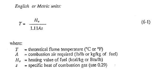
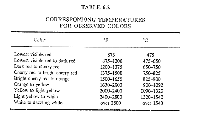
The values obtained by these calculations are usually in the magnitude of 370 800 F (2040-2650 C). At these temperatures the flame should have a dazzling white color. Comparing this with the color usually observed in a rotary kiln, it becomes quite obvious that actual flame temperatures fall quite short of these calculated maximum possible temperatures. Flames with a light yellow to white color [2400–2800 F (1320–1540 C)] and yellow to light yellow [2000–2400 F (1090–1320 C)] are common in rotary kilns. The flame colors discussed here are actual flame color and not the color an operator sees through a filter glass.
Operators often speak of hot and cold flames. These terms, although contradictory because there is no such thing as a “cold” flame, are fully acceptable because they state in unmistakable terms a given characteristic of a flame. What the operators mean by these expressions are high and low flame temperatures.
OXYGEN ENRICHMENT
The steel industry has made some large improvements in regard to flame temperatures in open-hearth furnaces by oxygen enrichment of the combustion air, resulting in much higher flame temperatures, which in turn improves the efficiency of this type of furnace. Oxygen enrichment of the combustion gases in a rotary cement kiln has been attempted in a number of cement mills, but because of the high cost the process has been abandoned. Using oxygen enrichment could create an undesirable result because of the extremely intense, ho and short fire that is characteristic of this type of flame. Extreme high temperatures might be localized close to the discharge area of the kiln which could cause damage to the refractory as well as to the burner hood and cooler.
It is quite conceivable that oxygen enrichment might, once again, find some favor and acceptance in a precalciner kiln. To the au.thor’ s knowl edge no plant has tried this so far. As previously stated, there are two types of precalciner kilns: the ones with tertiary air ducts and those that draw the combustion air for the flash furnace from the kiln itself. It has been mentioned that the latter must operate at very high kiln exit-gas oxygen levels to secure the proper air supply to the flash furnace. This leads to lower flame temperatures in the kiln itself due to the excess air present but makes this type of kiln considerably less costly than a precalciner with a tertiary air duct Besides, control of the kiln overall is also made easier by not having to control the air flow and temperature through the tertiary duct_ Oxygen enrichment at the flash furnace could possibly allow such kilns, without a tertiary air duct, to operate the kiln at normal oxygen levels in the kiln exit gas of say 0.8-1.5%. This idea would require research before deciding whether or not it could be feasibly implemented.
Flame D, Fig. 6.2, shows an extreme condition in which part of the
flame impacts against a clinker ring, a common condition on some kilns. Although such a ring formation speeds up the reaction of combustion (if enough air is present), this condition· is extremely harmful to the coating and refractory in the area immediately preceding the ring. It is not uncommon, on kilns that experience such frequent ring problems, to find the shortest refractory life of the entire burning zone lining in this Particular area where flame impingement upon the wall takes place. This is One of the reasons why it is a good practice to remove (shoot) the ring before it causes flame impingement, that is, before the ring has grown too large.
SHAPE OF THE FLAME
As previously pointed out, it is desirable to operate a rotary kiln with the total flame length as short as possible. A short flame extends the length of the calcining zone, which can often lead to increased production capabilities of the kiln.
Now consider Flames A and C in Fig. 6.2. Although the same amount of fuel is being burned in both flames, the two flames are entirely different. Flame A represents what operators call a “lazy” fire because heat from this flame is released over a relatively long distance of the burning zone. Flame C is a “snappy” fire in which· the heat is released over a shorter length of burning zone. Both types of flames can be found in rotary kilns, but flame ” C ” is more favorable for ease of kiln control, clinker quality, ·and fuel efficiency.
Flames such as shown in example A usually have a tendency to float about the kiln atmosphere in an unstable fashion, but flame C, with its so called better body, tends to remain fixed in position better when small changes in air-flow rates or temperature occur. Flame C, with only a few exemptions, is the most favorably shaped flame for a rotary kiln. The burning fuel (flame) expands in a uniform wedge equally in all directions along the kiln axis, and is not too short and not too long in total length. Stability of the flame must always be maintained and stable flame characteristics (when the flame is favorably formed) pay off with long refractory life and good kiln control conditions.
DIRECTION OF THE FLAME
One of the most important things for the kiln operator to remember is the fact that the path of the flame is not a straight line, and it does not remain constant at all times. Thus, when the primary air pipe is set for the fuel-primary air mixture to travel toward a certain target in the burning zone, this will not guarantee that the flame itself will follow this particular path for its entire length. The flame has a tendency to lift upward toward the top of the kiln arch, because of the buoyancy resulting from uneven entrance of secondary air into the kiln. This hot secondary air stream enters the kiln from the bottom, and moves upward in a curved path toward the axis of the flame a few feet past the burner nozzle, where it starts to mix with the fuel-primary air stream. Another factor influencing flame direction is the mechanical condition of the primary air pipe nozzle. Because of the high temperatures prevailing under normal operating conditions in the burner hood area, this primary air pipe nozzle is especially vulnerable to warping and distortion, resulting in uneven envelopment of primary air around the fuel jet causing erratic flame shapes and direction.
ADJUSTMENT OF FLAME DIRECTION
On some rotary kilns, the primary air pipe is fixed slightly below the center of the kiln, in an effort to offset the flame buoyancy. Most kilns, however, have facilities for adjusting the position of the primary air pipe and the burners, thus the operator can change flame direction and, to a limited degree, change the shape of the flame. Every adjustment in the primary air pipe or burner position will bring about a change in flame characteristics and can therefore affect burning conditions in the burning zone. Buoyancy of the flame can usually be counteracted by a slight downward tilt of the primary air pipe so the main body of the flame will be centered at a certain distance inside the burning zone. In Fig. 6.2, flame E shows a buoyant flame with the primary air pipe centered in the kiln axis. By tilting the pipe down slightly, the flame assumes the position shown by flame F.
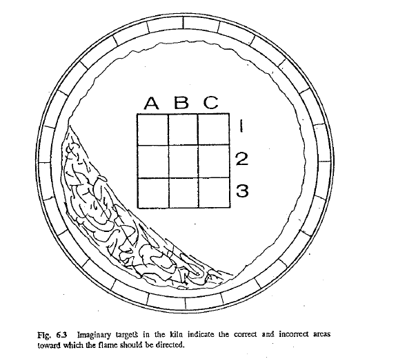
Because so many factors influence flame direction, it is necessary to fix the primary air pipe position according to the actual flame condition encountered in each individual kiln. To do this, the operator will observe the flame in the kiln, paying particular attention to the position of the flame body at point “x” in Fig. 6.2. Fig. 6.3 is a cross section of the kiln at “x.”
The center point of the flame at this location can be in any one of the indicated squares depending on how well the flame direction is adjusted. It is generally assumed that the best heat exchange between the flame and the feed takes place when the flame is pointed slightly toward the feed bed, hence the most favorable target for the flame is position 2A or on the kiln axis (2B). On the other hand, if the flame is directed too close to the feed bed (3A), tl1ere is danger that part of unburned fuel (especially on coal and oil fires) could enter the feed bed, a condition that is highly undesirable. A flame target leaning too much toward the kiln wall (lC, 2C, or !B) could result in flame impingement upon the coating, an action which is known to shorten the life of the refractory.
It has been found that ·the best method to fix the burner position is in the following manner: Prior to frring up a kiln (after a relining job), measure a given distance, e.g., 20m (65ft) from the kiln discharge and lay a white rag at this location. Then, go back to the frring floor and look through the burner (a cross-hair at the tip is helpful) to target the burner direction toward this rag. Once this is accomplished, tilt the burner slightly toward the load-side, e.g., the 5- or ?-o’clock position from the rag). The distance to place this rag is found by trial and error, for in some instances 80ft is required and other times only 50ft is necessary to obtain optimum flame positioning. Once this position has been found, however, it should not be changed and should become standard procedure on all subsequent kiln-start preparations.
Although no clear-cut standards can be given for the direction of the flame for all kilns, because each kiln has this position specifically tailored to i own particular problems, design, or conditon, there are, however there are few rules that can be applied to all flames, regardless of what rotary kiln is under consideration. These are:
a)When the primary air pipe nozzle has accidentally been warped, resulting in an erratic flame shape and direction, immediate steps should be taken to repair this Conditions.
B)A flame should never be allowed to impinge upon the coating or bare refractory for a prolonged length of time.
c)A flame should never be allowed to strike too hard upon the feed bed.
D)Oil burners or gas burners should be centered well in the primary air pipe in order that an even envelopment of air around the fuel jet takes place.
E)Flame direction should be adjusted only when the kiln is in stable operating condition and the temperatures, fuel pressures, and air flow rates are at a normal level. Flame direction changes can be caused by unusual operating conditions. If an attempt were made to adjust the flame direction at such times, there will most likely be an undesirable flame once the kiln returns to normal operating conditions again.
F)It is better to make the desired adjustments in flame direction in several steps instead” of a large one in order that the operating stability of the kiln is not affected adversely.
G)Once the ideal flame direction has been obtained, the primary air pipe position should not be changed unless a definite reason (such as to combat ring formation or hot shell conditions) makes it desirable.
H) To protect the primary air pipe from possible damage during a shutdown a certain amount of primary air flow must be maintained until the temperature inside the kiln is low enough (approximately 600 F or 315 C) that tl1e pipe cannot be damaged. Upon power failure when the primary air fan stops, the primary air pipe must be immediateiy removed from the burner hood.
TEMPERATURE OF THE FLAME
The amount of heat released by the flame depends on the flame temperature, and the flame temperature indicated by the color of the flame (Table 6.2). By observing the color, the operator can estimate the flame temperature within certain rather broad limits. However, before discussing color of the flame, it is first necessary to point out that an increase in fuel rate does not always increase heat output of the flame, nor does a fuel rate decrease always reduce the heat output. The reason is that combustion of the fuel is also dependent on the proper amount of air (oxygen) available and upon the prevailing temperatures of the gases and the kiln wall in the burning zone. Liberation of heat by the fuel, because of its dependence upon these factors, can at times be somewhat erratic and confusing to the newcomer who is learning to operate a kiln.
A prime example, and because of its simplicity and frequency of occurrence, the best worth mentioning, is the condition in which the kiln is operating with a very low content of oxygen in the exit gases, e.g., 0.5%. The operator notices that the burning zone temperature starts to decrease. The wrong procedure in many such instances is to increase the fuel rate, hoping that this will help-to raise the temperature. The contrary is most likely to happen; tloat is, a further decrease in flame temperature, because of the insufficient air supply available for good combustion of the fuel. The proper procedure in such an instance would be to reduce the kiln speed to allow more time for the clinker to burn properly, or to reduce the fuel rate to improve combustion of the fuel. A third possibility is to increase the primary air flow to compensate for the lack of necessary combustion air brought about by the increase in fuel rate.
The same or similar reaction can take place with a sudden large drop in secondary air temperature, or when too much air (large percentage of excess air) is introduced into the kiln by excessively high I.D. fan speed. Both of these occurrences can result in a decrease in flame temperature.
Under any operating condition, regardless of the fuel rate, it is desirable to obtain the highest possible flame temperature. In other words, the best fires in a rotary kiln are the ones with a very bright color. Orange and red colored flames are undesirable because they possess a lower flame temperature. The values shown in Table 6.2 are not only helpful in respect to flame temperatures, but can also be of service to the operator for any kind of observation in the kiln system where elevated temperatures prevail such as the burning zone wall, feed bed, and kiln shell.
Of specific interest for the kiln operator are the following factors that serve to raise flame temperature:
- Increasing tl1e secondary air Temperature.
- Using less primary air, tl1us making it possible to utilize more secondary air which is preheated to higher Temperature.
- Promoting rapid mixing of the air and fuel upon leaving the burner by improving the design of primary air pipe and burner.
- Better atomization of the fuel oil by increasing the fuel oil temperature and selecting a smaller burner orifice size (tip size), or employing a mechanical device in the burner nozzle to bring about better atomization.
- Operating a kiln with neither a deficiency nor excess of air by maintaining oxygen content of not Less than 0.7% and not more than 3.5%.
Simple and practical guidelines. Good
Excellent publication
we would like to fire the carbon black powder through multi channel kiln burner.Our 212 micron of carbon black powder is 35%.Any comment?