Contents
Grate Cooler

1. Introduction
- Clinker Cooling is an Important phase in clinker production
- Clinker Cooler is exposed to extremely difficult operating-conditions with a highly abrasive and hot material.
- The Cooling Rate of clinker at elevated temp. has direct impact on cement strength(fig.1).
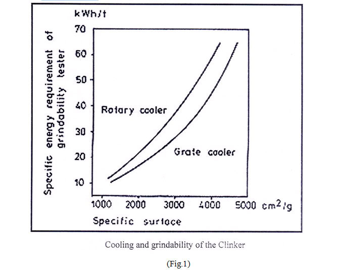
(Fig.1)
- Four types of clinker coolers were developed the earliest was the shaft cooler then the rotary cooler and satellite and finally the grate type cooler
- Of these types the discussion will be focused on the grate type cooler and the modifications carried out including the employment of air beam technology and reaching the up to date cooler innovation namely SF cross-bar cooler
So the discussion will be categorized into three parts as follows:-
- Conventional reciprocating grate cooler
- Modified air beam cooler (Coolax-cooler)
- Cross-bar (SF) cooler
2. Types of Grate Coolers
- The grate type cooler is the most suitable cooler for pre-calciner kiln and for kilns with a high outputs
Nowadays grate cooler are designed for large kiln capacities up to 10000 t/d
It’s based on cross-current cooling air.
The grate coolers can be divided into two main types:-
- Traveling grate cooler
- Reciprocating grate cooler
2.1 In the traveling Grate type
- A Continuous loop of grate segments transports the material from the feed end of the cooler to the discharge end and then returns to the feed end to receive a new load of material
- The material is transported in bulk without any (individual particle motion)
- This type of material transport greatly reduces the heat transfer efficiency
- Carrying a fixed bed of material on a traveling grate without benefit of individual particle movement leads to (rat-holing).
- In this phenomenon a large quality of air will blow through a small area of low resistance while the surrounding grate area receives little or no air flow
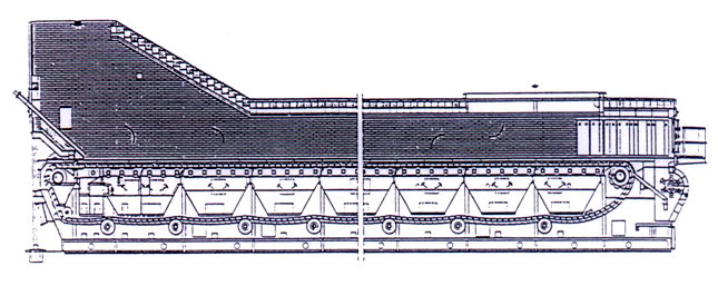
2.2 Reciprocating Grate cooler
- It have been used for years as an effective means for clinker cooling
- The basic concept of the grate cooler is quite simple
- Hot material enters the cooler and travels across a series of grate plates
- These grate plates have holes in them to allow the passage of cooling air
- Pressurization fans supply air to compartments beneath the grate plates
- As the material passes across the grates, this air is forced up through the grate plate and through the bed of hot clinker producing the desired cooling effect
- The reciprocating grate action provides particle turnover to expose each clinker surface to contact with air current
- A comparison made between various types of coolers, claimed generally 5% more heat recuperation of the reciprocating cooler versus the traveling grate cooler
- The higher efficiency was explained by the tumbling action of the clinker as it travel across the stepped grate plates
2.2.1 Grate line Configuration
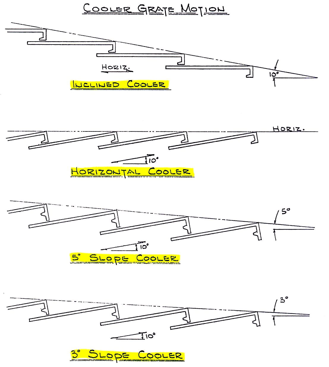
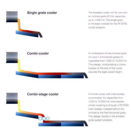
I- 15o Cooler :
Old cooler had a grate line with 15o slope this slope experienced material fluidization and run off the grate, preventing build up a deep clinker bed
II- 10o cooler :
– It was obtained by decreasing the grate line slope
– As the kiln capacities increased, cooler grate area became larger meaning longer grate lines and more headroom required for installation.
III- Horizontal Cooler: It was simply developed by laying back at 10o cooler until grate line became horizontal
- Although the grate line was horizontal the grates traveled up to a 10o slope during the forward travel
- The conveying efficiency was reduced because of this grate motion which became one of the drawbacks of horizontal cooler.
- Higher under grate pressures were required to maintain flow of cooling air.
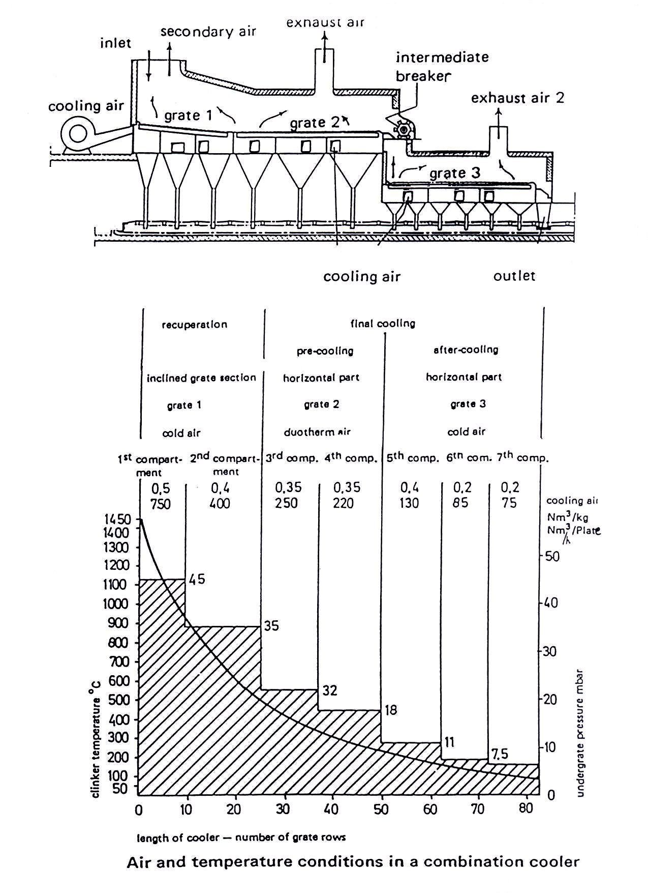
IV- Combination Cooler 5o slop / Horizontal
- The grate line at feed end was sloped at 5o while the cooling zone grate was horizontal
- This Cooler seemed to be not suitable for large capacity kiln due to material segregation phenomenon in cooler feed end.
V- Combination Cooler 3o sloped horizontal
- In order to avoid the effect of segregation and (air – sliding) of fine material, the grate line at feed section was reduced to 3o ; however this did not eliminate both segregation and fluidization and problem were still encountered with
2.2.2. Mechanical Features:
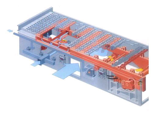
- From a mechanical stand point the cooler consists of alternate rows of per forted and overlapping stationary and moving grates. Grate plate supports to which the individual grate plates are attached are carried by the cooler side frame for the stationary rows and by a movable frame for the movable rows
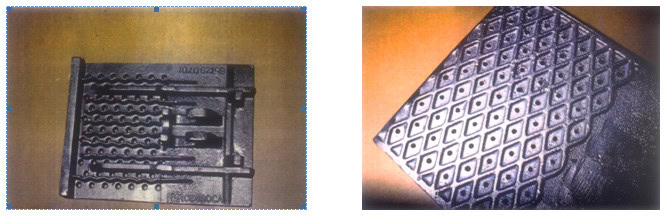
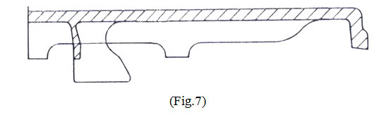
A. Grate Plates
A-I- Hot Zone. Required properties:
- Resistance against oxidation (800oC up to 1000oC)
- Resistance against cracking
- Good mechanical properties at high temperature (creep, deformation)
Material (25/25) or (25/20)
A-II- Middle & cold Zones: less critical problems due to lower temperature, required properties:
Wear resistance material
Material (25/12)
A-III- Manufacturing of grate plates:
Important tips:
- Perfect in critical zones (nose and hook)
- Residual stresses: must be avoided by heat treatment for stress relieving
A-IV- Important data:
- Chromium (Cr):
- Melting point 1890oC
- It increases the tensile strength of steels by 80-100 N/mm2 per 1% Cr
- Increases wear resistance
- High temperature strength
- Nickel (Ni):
- Melting point 1458oC
- High temperature strength
- Clinker hardness (500 – 700) Hv
B. Grate plate support
- Grate plate supports act as a carrier for grate plates (fixed and movable)
- These supports are arranged cross wise and lengthwise of the cooler
Alternating rows of fixed and movable supports cover the entire grate area(Fig.8)

- For fixed type supports it rest on cooler side frame and fixed central beam
- Movable supports are attached to movable frame with weldment stands
- Those supports used in hot zone are subjected to higher temperatures and possible impact of coating chunks from the kiln, so these are designed with deep truss sections
- Typical support material for this hot zone of the cooler GS 17 Cr Mo 55
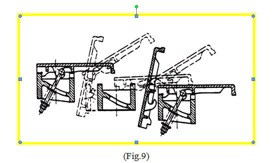
Replacement of grate plates is possible from the under grate chamber(Fig.9)
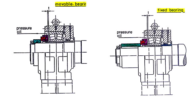
C. Moving frame:
- Moving frame is supported by shafts (running axles) and wheels (carriages) running on rails outside cooler housing .
- Running axles: are external penetrating the cooler housing through air sealing box assembly.
- These axles are fitted with tyres
- Drag (drive) shaft is fitted to the moving frame employing locking assemblies (ring feeder) in which force is transmitted by contact pressure and friction between functional surfaces.
- Wheels are fitted to drag shaft provided with shaft seal
- At the point when the drag (cross head) shaft penetrates the cooler housing a spring loaded adjustable sliding seal prevents loss of cooling air.

- Movable frame receives its motion via connecting rods to a crank type shaft driven by a sprocket and chain connected to a reducer with a variable speed motor.
- Bearing for the cooler drive and supporting shafts are of anti-fraction type (spherical roller bearings).
D. Air compartments & flap valves:
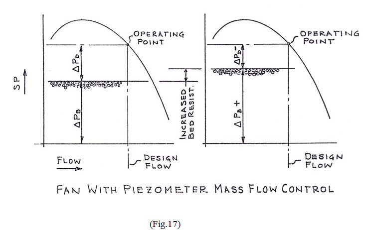
- The under grate area is divided into compartments each provided with separate fan equipped with adjustable inlet vanes for automatic air flow and minimum power consumption.

- It’s necessary to provide a good sealing between compartment to maintain each compartment as an (air-tight) box, so that the air can only pass upward the cooler grate and clinker bed
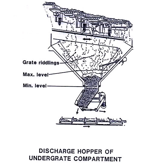
- Clinker spillage through the grates and the gaps between them during normal operation is collected in hoppers and removed through airtight flap valves to clinker conveyor.
2.2.3. Grate cooler operation and control
- Efficient grate cooler is not related to its mechanical design features, a very important factor is the method used to operate and control.
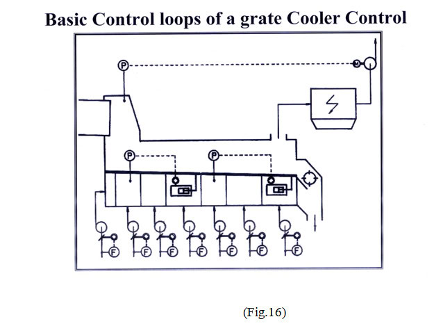
- Proper cooler operation and proper protection for the cooler demands an automatic variation in damper setting of cooler fans to provide the proper air flow at the times of steady and upset operation conditions.

- To maintain the proper thick bed of clinker on the grates for high cooling efficiency and recuperation to the kiln, while at the same time protecting against excessive thickness which could produce a shortage of air and damage to the cooler, it’s necessary that the speed of the grates be controlled automatically
- Each section of the grate cooler that has its cooler own drive is independently controlled by the press of the first compartment or second under grate comp.
- The speed of the grate can be varied between 3 and 30 strokes/min
- Normal operation would be around 10-15 strokes/min
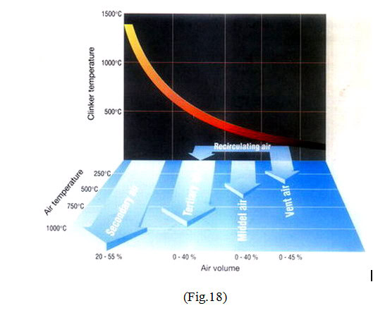
- After the cooling air has passed upwards through the grates, bed of clinker and is heated, it passes into a large plenum chamber over the grates.
- From this chamber the kiln by its own draft, draws part of air as a secondary combustion air.
- Some other part is drawn as tertiary air for combustion in flash calciner
- The balance of air not required for combustion is vented to atmosphere through a dust collector system (graved bed system or EP.) by means of an induced draft fan.
- To maintain smooth operation and avoid pressurization of the cooler, it’s necessary that the cooler vent fan be automatically controlled by the pressure of kiln hood
Thus efficient cooler operation requires three main functions:-
- Constant airflow to each compartment
- Regulation of grate speed for constant bed
- Constant negative thickness pressure in kiln hood
3- Clinker Crusher
Introduction:-
- At the discharge end, the cooler is fitted with clinker crusher to break over sized particles of clinker or pieces of coating which
- Attribute to kiln upset conditions
N.B
Some grate coolers specially combined cooler with 3 grates, has the clinker crusher installed after the 2nd grate the objective here was to achieve not only the best possible quenching effect of the exposed interior surfaces of the broken clinker chunks, but also the lowest possible final clinker temperature
- Two types of clinker crushers are in current use:
* Hammer breaker
* Roller breaker
The clinker breaker of hammer type consists of the following:
- Hammers which are cast manganese steel
- Pins and spacers
- Hammer hubs (discs).
Shrink fitted to crusher rotor
- The hammer pin is retained in its position by means of asset of collar (spacer)
- The set of collar is located between two ears on the hammer
- The hammers extend over the hub to give protection during operation
3.2. Grizzlies
Ahead of the breaker is a grizzly bar assembly to permit passage of mat. Of small size
One of the disadvantages of hammer crusher is the possibility of blocking in case of over sized clinker lumps
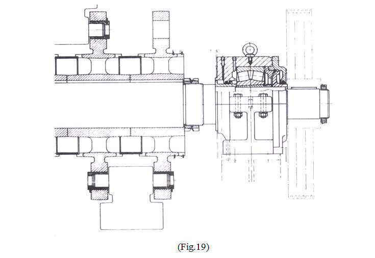
3.3. Roller Crusher
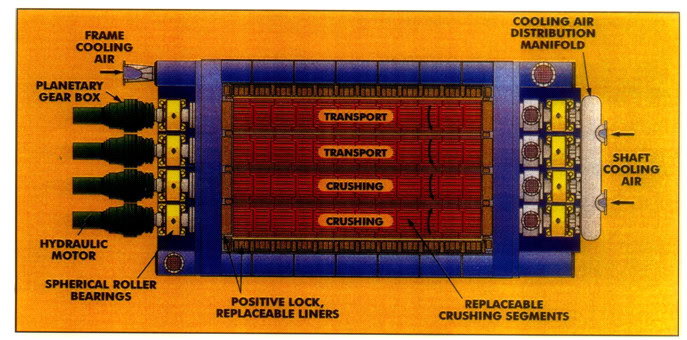
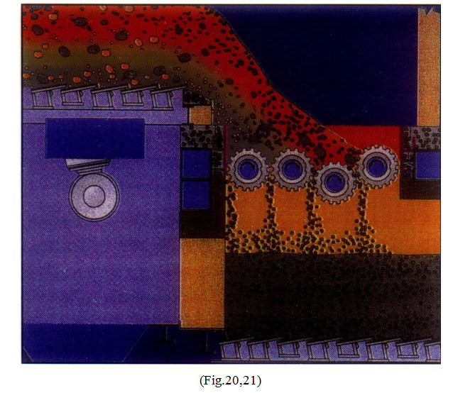
– The roller breaker consists of several (air – cooled), hydraulically driven crusher rolls whose operation width matches the width of the cooler grate
– The advantages of the roller crusher are:
- High temp. Resistance up to (800C – 850C)
- Low speed of roller rotation, reducing dynamic load on the surrounding and minimizing dust generation
- Long life crushing rings
- Even grain size reduction
- Low power consumption
4. Problems of standard cooler
- Mechanical problems
Typical mechanical problems include the following:
1- Sinking of movable frame
* Due to wear on bearings and carrying rollers
2- Grate plate cracking
- Due to incorrect grate plate material, shock load on plates during handling or by coating and finally
- Due to over heating of plates
3- Burnt grate plates
- Due to over heating came by snow man formation, red river, too thin layer of clinker and in sufficient cooling air
4- Loose grate plates
- Due to incorrect compression spring material and incorrect tightening torque of bolts
- Grate plate problems
Which include the following:
Wear by sand blasting with conventional grate cooler vertical air jets cause reveres flows which catch some fines and blow them against the grate plate surface (fig.22)
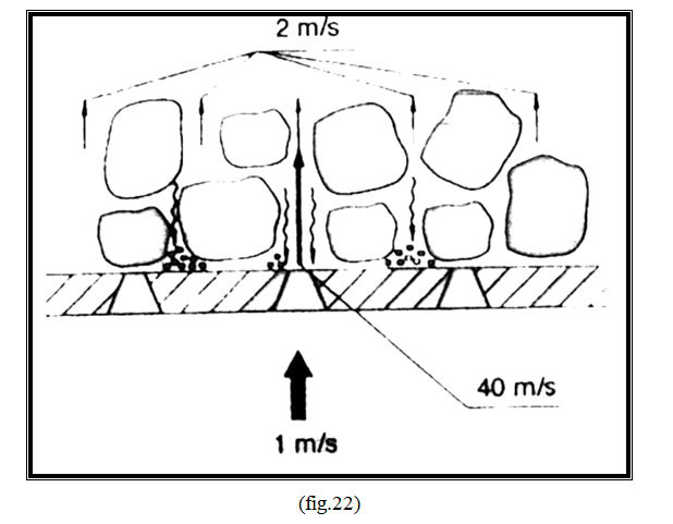
- Abrasion of grate plates: due to transportation of hot abrasive clinker
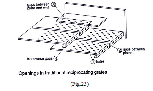
- Wear of side cast plates: due to hot fine clinker flowing adjacent to side plates, causing deformation of side frame(fig.23).
5. Developments Related to Grate Cooler
These developments include the following :-
* Dead grates
* Reduced fall through grate I
* Air beam technology.
* Stationary inlet section.
1- Dead grate plate (bridge plates)
- Dead grates were installed adjacent to the side casting on each side of the entire cooler length and mounting to the stationary grate plate supports
- The dead grate covered with castable, thus protecting the cooler side walls
- The bridging plates allow deep bed operation, improving cooling efficiency
2- Reduced fall through (R.F.T) grates:
- The plates were designed to reduce spillage into the under grate area by means of labyrinth in the type slots(fig.24).
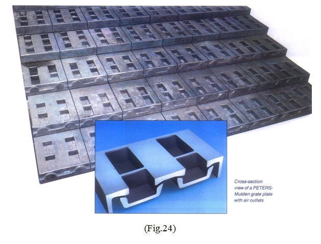
- These slots promote the uniform distribution of cooling air into the clinker bed
- Reduced fall through grates are designed to be mounted on conventional grate plate supports with open bottoms
3- Air beam technology:
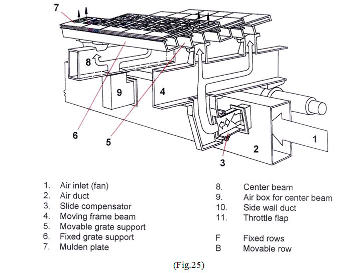
- Air beam systems prevent the possibility of cooling air by – passing the clinker layer.
- It works by improving air distribution below the grate by connecting individual rows of the cooler directly to the air supply
- In such systems the grate plate support are used to duct, the cooling air directly to the grate plates and into the clinker bed
- Air beam system is used on both the stationary and moving rows of the cooler
4- Stationary inlet Section
- This design delivers high degree of utilization and minimize overhaul maintenance costs due to eliminating wear because of absence of any moving parts.
6. Design features of modern grate cooler:
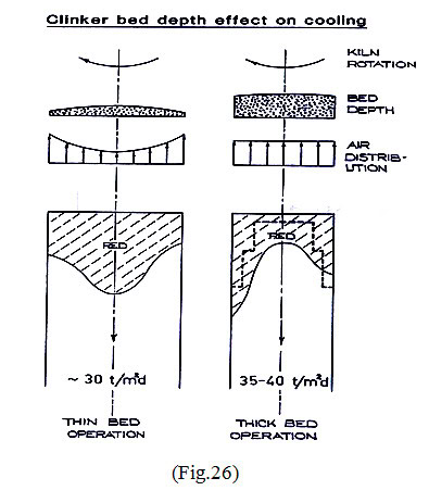
- Specific grate loading in (ton/day/m²) for the cooler as a hole is (35 – 40) (t/m². day)
- Installed cooling: air quantity in the range of (3 – 3.5) Nm³/Kg with fan pressure of (60 – 70) in bar in the first compartment, decreasing to (20 – 30) in bar in the last compartment
- Clinker bed depths range from 800mm in the inlet zone to 300mm in the outlet zone
- Loading to increase of plates service life
- Limiting grate inclination for the 1st grate to a maximum of 3 degrees
- Horse shoe – shaped arrangement of the plates in the inlet zone is standard to improve the clinker distribution and control (red – river).
7. Grate Cooler Retrofit
- Upgrading exiting grate cooler include the heat recuperation zone and in some cases extends to the after cooling zone
- The purpose of (retro fitting) (an exiting grate cooler) energy saving (reducing losses cooler & increase of hourly by production within the overhaul dimension of exiting cooler.
8. Maintenance on Grate coolers
- a) General Remarks
Maintenance on a cooler consists mainly of:-
- Planned servicing of parts (e.g. lubrication, adjustments, cleaning)
- Planned detection and replacement of worn and damaged parts
- Keeping control instruments functioning
- Improvement of weak-points on the equipment
- Keeping records on the maintenance activities
Each unit or component of the cooler shall be considered and analyzed bearing in its:-
- Weak-points
- Functioning and design
- Effects of wear and tear
- Influence of high temperature
- Fatigue due to dynamic loads
By elaborating maintenance schedules the suppliers manual and instruction ought to be consulted as well as exiting plant experiences.
- b) Operational effects of cooler maintenance
Correct cooler operation helps keeping routine maintenance and breakdown costs low
A correct cooler operation means operating the cooler with a deep and even clinker bed:
- With low grate speed resulting in low wear and tear
- With high cooling efficiency resulting in reduced wear and tear as well as low temperatures on all components
Correct cooler operation again requires correct functioning of all control, measuring and regulating equipments (temperature, flow, pressure, speed, level, TV.,…)
- c) Basic preventive maintenance requirements
The following suggestions require to be adapted to a given cooler, by taking into account the local condition and the specific design characteristics of a cooler.
1- Inspection and services to be done each shift
- General (walk around) inspection (leaks, noise, irregularities etc.)
- Check temperature and vibration (by hand) of bearings and drives
- Oil level inspection on gears
- Central lubrication system, check for functioning and leaks in piping, check grease reservoir
- Check through inspection windows the functioning of the lighting, check for excessive flow of riddling or irregularities in the under grate compartment
- Check proper functioning of hopper discharge
- Check transport of clinker and riddlings
- Check fan intake for cleanliness
2- Weekly Checks and Services
- Lubricate manual lubrication points
- Top up lubricant reservoirs
- Check functioning of control and measuring instruments (pressure, temperature, flow, TV camera)
- Check tension of v-belt drives
3- Monthly vibration Measurements
- Measurements on drives, fans and bearings
4- Maintenance work for a short cooler shut-down
- General internal cooler inspection
- Inspect the grate plates particularly the first rows of the first grate replace any cracked or damaged plates, tighten loose plates
- Inspect the lateral wear plates
- Inspect the supports of the moving frame (rollers and rails)
- Inspect lubrication piping for leaks inside the cooler
- Inspect and adjust cooler seals (between compartments, shaft seals…)
- Replace hammers if required on the clinker breaker
- Inspect the grizzly bars and chains
- Inspect refractory material, clean out material build-ups
- Clean and service inspection windows and lighting
- Clean and inspect visually control and measuring instruments
- Clean and service the TV. Camera
- Inspect the cooler drive
- Inspect visually the hydraulic dampening gear on the moving frame
- Inspect visually the fans
- Tighten or replace v-belts
- Inspect visually hopper discharge flaps
- Inspect visually the clinker transport equipment
5- maintenance work requiring a longer cooler shut-down (once a year)
Cooler Drive (DC Drive)
- Change the oil, clean the gear and the filters and breathers
- Visual gear inspection
- Check coupling alignment and general condition, lubricate if required
- Retighten base bolts
- Check staring clutch (if installed)
- Check, clean, lubricate chain drive and tension (if installed)
6- Crank shaft, connecting rod, Drive shaft
- Check all bearings and bushings for wear
- Check all stop screws,keys and circular spring tensioning elemts,retighten as required
- Retighten all bolts
- Check sliding seal and drive shaft, check for wear
- Clean and check wheel unit and guide rails, measure wear on rollers, readjust
7- Carrying Axles
- Check all bearings
- Check all wheel rims and guide rails for wear (measure) and fasten, readjust as required
- Check the sealing unit and service as required
8- Moving Frame
- Check alignment of the frame (leveling and clearances) realign if required.

- Check movement of the frame (no contact between fixed and moving parts, observe clearance for thermal expansion)
- Check for thermal overload deformation and cracks
- Check partition walls and sealing
- Check lateral moving frame guides
9- Grate Components
- Check grate plates, grate supports, side castings and/or support bracket plates, end castings and/or cover bracket plates for wear cracks or damage. Burnt, worn or damaged parts have to be replaced
Note: Replace grate plates of the first 4 rows, if possible use the old plates which are not damaged for replacement of plates in the lower grate section.
- Check all mounting bolts for tight seat
- Check mounting and functioning of thermo-couples
10- Clinker Breaker
- Clean and check bearings (Fig.31 A,B), measure clearance, fill with new grease, replace seals, check seat of bearings of shafts, tighten bearing base bolts.
- Check rotor, hammers and pins, replace hammers and balance rotor
- Check functioning of rotor motion switch
- Check v-belt drive, change v-belts, align and tighten base bolts
- Check impact plate, chain curtain, grizzly and clinker discharge chute for wear and damage clean grizzly
11- Clinker Transport, Drag Chain
- Check, clean and service drive, replace v-belts, realign and tighten base bolts, change oil, check shear pin
- Clean and check all bearings, refill with new grease, tighten base bolts of housing, replace seals
- Check sprockets, idlers and tail drum for wear (measure)
- Check chain links for wear, cracks or damage, renew armoring if necessary, tension chain
- Check chain supports for damage and wear
- Test-run the chain drive
12- Clinker riddling Hopper and double Flap Gates
- Check and clean hopper
- Check functioning of level indicators
- Check double flap gate, check wear on flaps seals, adjust for proper sealing, check functioning, check flap drive and service as required
13- Central lubrication System
- Clean and check pump and control components, test functioning
- Clean and refill grease tank
- Check lubricant distributors
- Clean filters
- Check lubrication points, pipe work and pipe protections, replace flexible hoses if required
14- Fans
- Check wear on impeller, repair or replace and balance if necessary
- Check and clean the casing and the air intake and ducting
- Seal all ducting
- Rinse and check all bearings, refill with grease
- Check v-belts, replace, tension
- Check v-belt pulleys and guards
- Check air flow controller including actuator
15- Measuring, Regulating and control Equipment
- Service and check functioning
16- Brick Work
- Clean suspended arch at top remove any material deposits
- Check suspended arch, suspending structure, casting, bricks
- Check brick lining of the cooler side walls including wear zone in the grate area
17- Cooler Casing and Ducting
- Inspect for damage, wear and leaks
- Replace seals as required
- Check insulation
18- Dedusting equipment
- See special instruction
- d) Maintenance record Keeping
All relevant preventive and corrective maintenance activities on the cooler shall be entered in the machine history.
- Grate plate record
- Damaged plates
- Replaced plates
- Modifications
- Plate wear
- Refractory material
- Damaged
- Replacements
- Modifications
- Moving frame alignment
- Alignment measurements
- Lateral clearances
- Rail and roller diameter (wear)
- Vibration measurements
- Fans
- Drives
please contact me as soon as you finish reading this article : project20062015@gmail.com
Hot blast valves for air heaters of blast furnaces. Cement industry equipment . The grate cooler is intended for cooling of clinker, alumina and other bulk materials by atmospheric air.
Usually I don’t learn post on blogs, but I wish to say that this write-up very pressured me to check out and do so!
Your writing style has been amazed me. Thanks, quite great
post.
Very excellent & fine article
Great blog right here! Additionally your site quite a bit up fast!
Appreciating the time and energy you put into your blog and detailed information you provide. It’s nice to come across a blog every once in a while that isn’t the same outdated rehashed information. Wonderful read! I’ve saved your site and I’m including your RSS feeds to my Google account.
Excellent, article has very useful explanations for amator engineers and operators.
require solution for bull nose castable failure in grate cooler
hello, I would like if possible to get some technical details about a replacement of a planetary cooler in a clinker kiln, with a grate cooler one.what are the prliminary preparation jobs to do, mechanical, civil works ,etc.
Can I have an estimation of the time for such a job fromclinker to clinker, for an FLSmidth 1500 tpd kiln.
Is it necessary to change the kiln shell, invert kiln live rings ? all the information is interesting to know ,such a way we can succeed in this replacement. Thanks in advance