Quick answer
A change in cement ball-mill power and acoustic trends is a diagnostic signal, not proof of liner wear. Compare verified mill input power and specific energy with throughput, feed characteristics, mill speed, grinding-media charge, ventilation, and measurement conditions. Review acoustic and vibration trends at comparable duty. If the evidence warrants liner inspection, plan an authorized shutdown, control all hazardous energy and stored material, and assess liner condition against the installed design and OEM wear criteria. Replace components only where inspection and engineering disposition justify it, then verify performance after controlled recommissioning.
Problem / Job
This guide addresses a rotating horizontal-axis cement ball mill where operators observe changes in specific energy consumption and sound. The task is to determine whether the trend reflects liner condition, grinding-media condition, process changes, instrumentation error or another mechanical issue before selecting corrective work.
Evidence
- Retrieve actual input-power, production-rate and specific-energy trends, noting instrument source, units and the duration of any confirmed deviation.
- Compare sound-level or acoustic-monitoring data taken at documented measurement locations and comparable operating conditions; do not assume a fixed frequency band diagnoses liner wear.
- Review bearing vibration spectra and trends for corroborating mechanical evidence without attributing a change to the liners prematurely.
- Check feed size distribution, moisture, grinding-media charge, mill speed, ventilation and separator operation before comparing performance.
- Review liner installation, inspection and replacement records; service age alone does not establish remaining liner life or a wear-related failure.
Decision
Do not assign liner wear as the root cause from power, noise and elapsed service time alone. Validate measurement quality and process comparability, then use relevant operating trends, maintenance history and inspection evidence to distinguish liner wear from media, feed, ventilation, drive or bearing issues. Where inspection is justified, follow the mill-specific isolation and safe-entry plan and compare liner profiles, attachment condition and thickness with approved manufacturer or site engineering criteria. Document the corrective decision and verify the result at representative operating conditions.
7‑step diagnostic workflow
- Collect baseline data. Retrieve verified mill power, throughput, acoustic and vibration data from a documented representative operating period, where available. Store these values in a reference file.
- Confirm operating conditions. Record feed rate, feed-size distribution, moisture, media-charge information and relevant ventilation or separator conditions for the comparison periods. They need not be identical, but differences must be quantified or acknowledged before drawing conclusions from the power and acoustic trends.
- Measure current power and noise. Calculate specific energy (kWh/t) using validated energy and tonnage over the same representative, documented interval. Define the measurement boundary explicitly: mill-drive energy per tonne of mill feed is not interchangeable with total grinding-circuit energy per tonne of finished cement. Use the same boundary, product basis and metering method for the baseline and current comparison. Where acoustic measurements are appropriate, use calibrated equipment at approved, repeatable positions under comparable load and speed; note background noise, measurement method and uncertainty. Do not assume that a bearing-gallery location or a particular frequency band is valid for every installation.
- Compare trends. Compare validated power, specific energy, sound and vibration measurements against an approved baseline at similar mill speed, feed rate, material properties, ventilation and grinding-media charge. Record actual deviations and measurement uncertainty; do not use an invented universal percentage or acoustic-frequency threshold to diagnose liner wear.
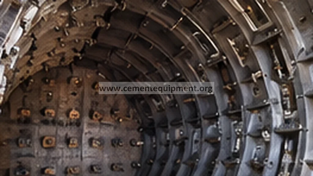
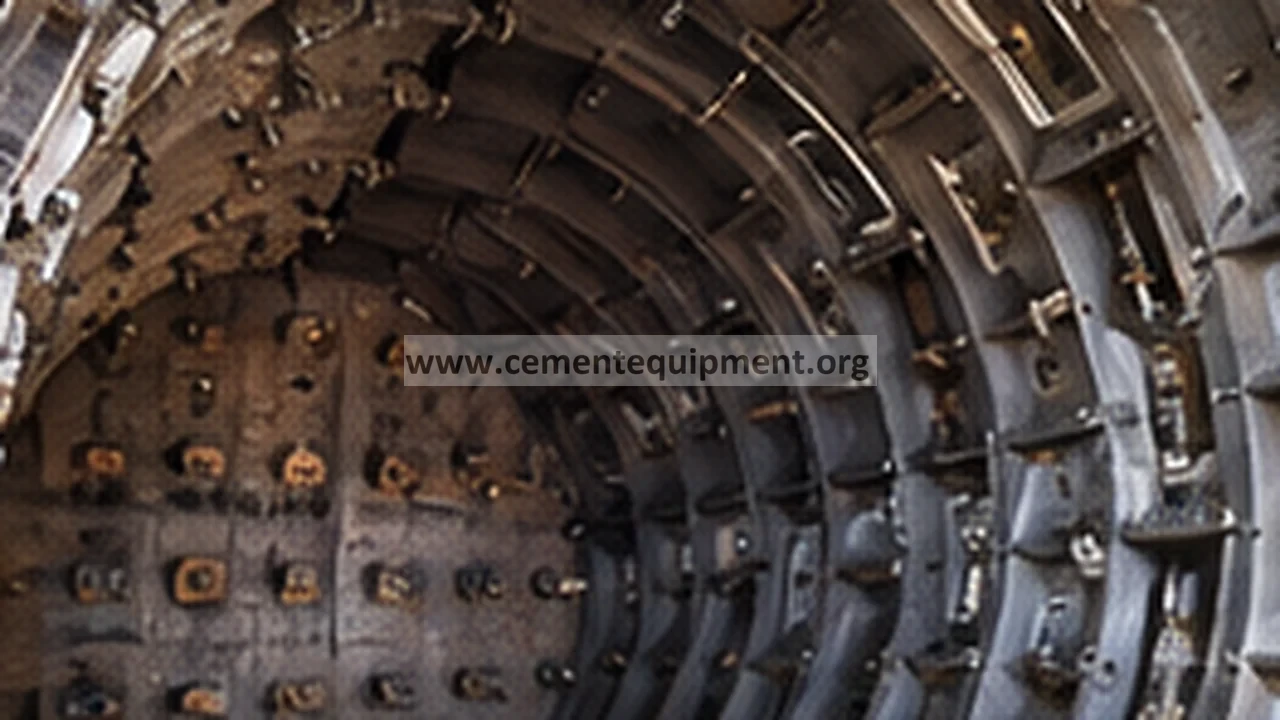
- Inspect liners safely. Plan inspection with authorized plant personnel using the mill-specific shutdown and hazardous-energy isolation procedure. Isolate the main and auxiliary drives, verify zero energy and prevent unintended rotation; address stored charge, hot material, confined-space entry, ventilation and falling liner or grinding-media hazards before any access. Do not automatically remove a discharge grate or enter the mill. Inspect accessible liner profiles, attachments, cracking and wear using approved methods; use calibrated thickness measurement only where suitable for the installed liner design and measurement access.
- Evaluate wear against approved criteria. Compare inspection findings with the installed liner drawings, wear profiles, attachment requirements and OEM or site-engineering rejection criteria. A thickness reading alone may not represent remaining safe service life. If the liner satisfies approved retention criteria, continue investigating other plausible causes; if the liner meets the applicable rejection criteria, obtain engineering disposition for repair or replacement. Continue to step 7 for verification of the chosen action.
- Validate corrective action. Confirm all inspections and maintenance are complete, guards and access points secured, personnel clear and isolation released only by authorized personnel. Restart under the approved commissioning procedure and compare verified power, throughput, specific energy, acoustic and vibration trends at representative conditions against equipment-specific criteria. Record findings, residual deviations and responsible engineering sign-off before closing the work order.
Diagnostic matrix
| Evidence | Likely direction of root cause | Next check |
|---|---|---|
| Validated specific energy rises at comparable production duty | Cause undetermined: feed grindability, media charge, ventilation, separator loading, drive losses and liner condition may contribute. | Confirm throughput, power metering and operating comparability before selecting an intrusive liner or media inspection. |
| Repeatable acoustic-spectrum or sound-level change at a documented measurement position | Possible change in grinding impacts or mechanical condition; the sound trend alone does not establish liner wear. | Compare recordings at matched mill load and speed; review process and media changes before attributing a cause. |
| Bearing vibration trend increases with corroborating changes in mill operation | Possible bearing, drive, charge-distribution or structural issue; liner wear is not established by a frequency band alone. | Review calibrated spectra, operating conditions, bearing temperatures and OEM alarm criteria; inspect only if supported by evidence. |
| No change in feed size or moisture | Does not rule out other process variables | Check broader process trends and measurement reliability before deciding whether a planned mechanical inspection is justified |
| Inspection documents liner cracking, insecure fasteners or wear beyond approved rejection criteria | A liner defect requiring engineering disposition is confirmed, but it may not fully explain the original power and sound changes. | Plan an OEM-compliant repair or replacement under isolation, then verify the full mill and grinding-process performance after recommissioning. |
Verification and acceptance criteria
After any corrective action, the mill must meet the following measurable conditions before the work is signed off. All limits are to be verified against the OEM‑published specifications or the plant’s own validated baseline.
- Specific energy consumption (kWh/t). Compare validated mill-drive energy per tonne of mill feed with an approved representative baseline using the same metering boundary, throughput basis and operating conditions. Do not label kWh/t as power draw (kW), or compare mill-only energy with whole-circuit energy; apply equipment-specific acceptance criteria.
- Sound‑pressure level. Compare calibrated acoustic measurements under comparable conditions and apply only site-validated monitoring and engineering acceptance criteria; no universal frequency band or decibel increase proves liner condition.
- Vibration response. Assess bearing and drive vibration against the installed equipment’s approved OEM or site alarm and acceptance criteria, using calibrated measurements and appropriate operating context.
- Liner condition. Document wear profile, attachment integrity, cracking and measured thickness where applicable; obtain engineering acceptance against the specific liner design and OEM or plant rejection criteria.
- Operational stability. Complete the approved controlled-startup and observation period with stable process and mechanical trends, functioning safeguards and no unexplained deviations. Set the observation period from plant-specific commissioning requirements.
Record the operating context, instrument identification, measured results, inspection method, corrective work and remaining uncertainties. Attach thickness measurements only where the method was suitable and performed, and obtain the approvals required by the site’s maintenance and return-to-service procedures.
Common mistakes and repeat‑failure traps
- Relying on a single data point. Interpreting a one‑shift power increase as definitive can lead to unnecessary liner changes. Assess an adequate representative trend window selected for the plant’s operating variability, data quality and diagnostic question; a fixed number of shifts is not universally sufficient.
- Skipping LOTO. Do not approach internal liners or perform intrusive measurements until the approved isolation, zero-energy verification, unintended-rotation prevention and safe-access requirements are satisfied. The principal concern is severe injury from hazardous energy, falling material or uncontrolled movement, not merely measurement accuracy.
- Neglecting upstream variables. Changes in feed moisture or particle size can also affect power and noise. Failure to verify these parameters may misattribute the symptom to liner wear.
- Using the wrong ultrasonic gauge settings. Confirm that the measurement method is suitable for the installed liner material and geometry, with documented calibration and uncertainty.
- Assuming liner replacement requires generic rebalancing. Follow the installed mill’s OEM requirements for liner installation, bolt tightening, charge distribution and recommissioning. Perform balance or runout checks only where the equipment design and measured evidence warrant them.
- Overlooking grinding-media wear. Worn or broken grinding media can produce similar acoustic signatures. Review operating and maintenance evidence first; inspect media only where justified under an approved shutdown and safe-access procedure.
- Documenting without baseline comparison. Use documented representative operating data and equipment-specific approved criteria; the most recent liner change is not automatically a valid baseline.
Related Infinity guides
Build a stronger cement maintenance library
The Infinity for Cement Organization technical package contains 900+ technical files. It is a one-time $249.99 purchase, with instant download immediately after payment and lifetime updates forever at no additional cost.