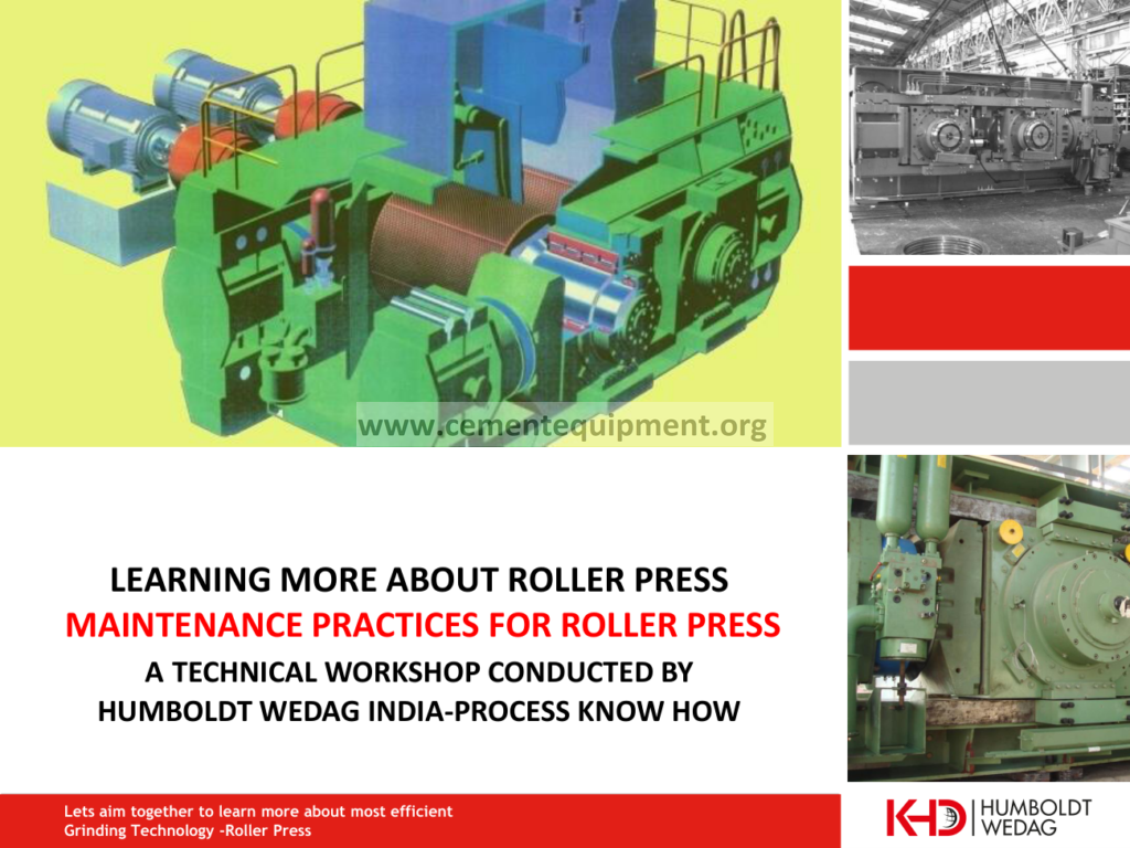

Roller-press surface wear becomes a production problem when wear is uneven, studs or hard-facing are lost, or the surface profile no longer grips and compacts material uniformly. Diagnose the wear pattern before welding or replacing parts: map surface loss across both rollers, compare roller gap and skew trend, check feed distribution and material bed across the width, inspect hydraulic loading and bearing condition, and look for tramp metal or oversized feed. A repair that restores only the damaged patch without correcting uneven loading can fail again quickly.
Decide whether roller-surface wear is normal campaign wear, localized feed/load damage, stud loss or a broader mechanical/process problem.
Use surface wear map, stud/hard-facing condition, roller gap/skew, hydraulic pressure, feed distribution, throughput, vibration and bearing condition.
Correct feed, skew, loading or foreign-material causes first; repair surface only after the wear mechanism is understood.
Fast diagnostic order
- Map the roller surface condition by zone and compare both rollers.
- Compare the pattern with feed distribution, grinding pressure, skew, and material characteristics.
- Check whether the condition is concentrated at the edges, center, or one circumferential region.
- Review stud condition, surface buildup, and recent process or maintenance changes.
- After correction, trend pressure stability, throughput, vibration, and surface condition over time.
Build a wear map before cleaning or welding
Record: wear depth/profile at several positions across each roller; missing or loose studs; cracked or detached hard-facing; gap and skew trend; hydraulic pressure on both sides; bearing temperatures; motor current; vibration; throughput; feed size/moisture; recent tramp-metal events; and whether the material layer entering the rolls is even across the full width.
Photograph the complete roller circumference and label the drive/non-drive side. Local repairs erase evidence, so map first and repair second.
1. Separate uniform campaign wear from localized abnormal wear
Uniform gradual wear across the working width is different from deep bands, edge wear, one-sided loss or isolated stud failures. Plot the wear pattern instead of reporting only an average. Localized wear usually means local load, feed distribution, skew or foreign-material effects. Compare both rollers because a matching band can indicate the material bed, while damage confined to one roller may point to its surface or mechanical condition.
2. Correlate wear with roller gap and skew
Unequal movement at the roller ends changes the pressure distribution across the bed. Review gap measurements and skew-control or LVDT trends where available. A persistent side-to-side difference can overload one zone and accelerate wear. Check hydraulic cylinders, accumulators and control response; do not merely compensate by adding hard-facing to the worn side.
3. Inspect feed distribution across the full roller width
A roller press needs a stable, well-distributed feed bed. Inspect feed chute condition, gates and any spreader or divider. Look for one-side loading, segregation, buildup and intermittent surges. If the center is heavily loaded while edges are starved, or vice versa, the pressure and wear pattern will follow. Correct chute buildup and feed distribution before judging the roller material.
4. Check studs or hard-facing attachment and surrounding base material
Missing studs are not only a surface defect. Inspect whether the stud fractured, loosened, pulled out with base material or was damaged by foreign material. Around hard-facing repairs, look for cracking, spalling and poor transitions that concentrate stress. Follow the roller OEM’s approved repair consumables, welding sequence and preheat/interpass requirements; uncontrolled welding can damage the roller body.
5. Investigate tramp metal and oversized feed
Foreign metal or unusually large hard particles can cause impact marks, stud loss and local spalling. Review metal-detector, magnetic separator and bypass records. Inspect the feed system for failed screens or upstream wear parts. A repeated damage location after tramp events may indicate the protection system is not reliably removing foreign material.
6. Check hydraulic loading and bearing condition
Uneven or unstable hydraulic pressure can change the grinding force across the machine. Compare left/right pressure and movement. Check accumulator condition and control stability according to the press design. Also review bearing temperature/vibration because abnormal roller movement or support condition can alter the gap and load distribution. Surface repair will not compensate for a mechanical support fault.
7. Use production performance as supporting evidence
Track throughput, specific energy, product fineness or downstream grinding response alongside wear progression. A worn surface can reduce material draw-in and compaction efficiency, but production deterioration may also come from feed size, moisture or circuit changes. Combine surface evidence and performance data before deciding when to repair or replace.
Roller-surface wear diagnostic matrix
| Wear pattern | Likely direction | Priority check |
|---|---|---|
| One side wears faster on both rollers | Feed/skew/load asymmetry | Feed distribution, gap/skew, hydraulic loading |
| Isolated broken studs with impact marks | Tramp/oversize impact | Metal detector, magnet, upstream screens and feed size |
| Hard-facing peels around previous repair | Repair/material/procedure issue | Base material, weld procedure, transition geometry |
| Progressive center band wear | Concentrated feed bed | Chute/spreader distribution across width |
| Wear plus unstable gap and vibration | Mechanical/hydraulic instability | Bearings, cylinders, accumulators and skew control |
Common repeat-failure mistakes
- Welding the worn band before mapping feed and skew conditions.
- Replacing studs without investigating tramp metal.
- Using average wear depth and missing severe local damage.
- Ignoring left/right hydraulic-pressure differences.
- Returning directly to maximum throughput before verifying repaired-surface behavior.
Return-to-service verification
After repair, verify roller gap, skew indication, hydraulic pressure balance and rotation according to the OEM procedure before full loading. Increase feed in controlled steps. Acceptance means no abnormal vibration or temperature develops, material distributes across the roller width, gap/skew remain stable, repaired studs or hard-facing show no early detachment, and production performance is consistent with the plant baseline. Re-map the repaired area after an agreed operating interval to confirm wear is again uniform.
Frequently asked troubleshooting questions
What causes uneven roller-press surface wear?
Common drivers include uneven feed distribution, skew, incorrect grinding pressure, material segregation, buildup and local stud or surface damage.
Can missing studs accelerate wear around the damaged area?
Yes. Local stud loss changes the protective surface pattern and can concentrate wear. Map the damaged area and compare it with feed and pressure distribution.
Should grinding pressure be reduced whenever surface wear is found?
Not automatically. Verify feed distribution, skew, operating pressure, material condition and the OEM surface-wear limits before changing the normal process setting.
Related Infinity technical guides
References
KHD Roller Press service guidance uses surface scanning and historical wear data to identify progressive wear and abnormal damage; roller-press operating guidance also emphasizes consistent feed and controlled roller position/skew. Repair materials, welding procedure, stud replacement criteria and allowable wear must follow the installed press OEM.