Cement Conveying Systems: Complete Guide
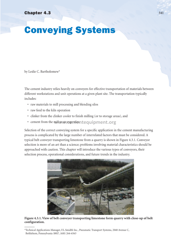
Conveying systems are the bloodstream of a cement plant. Every tonne of limestone, clay, sand, iron oxide, coal, raw meal, clinker, gypsum and finished cement must be moved repeatedly between crushers, mills, silos, kilns, coolers, packers and loadout points, and the efficiency, availability and maintenance cost of these transport systems often decide the overall plant performance more than the process equipment itself. This article, based on the classic conveying system chapter written for the cement process literature (by Leslie C. Bartholomew, in the Innovations in Portland Cement Manufacturing reference series), explains how to select the right conveyor for every duty in a cement works: the selection criteria that go far beyond first cost and power consumption, the strengths and limits of each conveyor family (belt, bucket elevator, screw, pneumatic, airslide, apron and drag conveyors), and the practical engineering rules that make a conveying system reliable for decades. The complete 28-page chapter is part of the Complete Cement Technical Package, the 931-file library of books, manuals and Excel tools available from cementequipment.org.
Conveyor selection is frequently described as more of an art than a science. The reason is that material characteristics interact with machine mechanics in ways that no single formula captures: a material can flow beautifully through an airslide in a laboratory test yet bridge and flush in a full-scale silo; a bucket elevator that handles clinker for years can blind its buckets with wet clay within a month. This guide therefore presents the systematic selection framework used by experienced cement plant engineers: define the mode of operation, the distance and lift, the material characteristics, the safety requirements, and only then match the conveyor type.
1. The Role of Conveying in the Cement Manufacturing Process
A modern integrated cement plant performs four fundamental material transport missions, each with its own conveyor selection logic:
- Raw materials to the mill processing and blending silos: quarry limestone, clay and additives are crushed in primary crushers and carried over distances that can range from a few hundred meters to several kilometers of overland belt conveyor. The duty is high tonnage, large lump size, abrasive and dusty.
- Raw feed to the kiln operation: dried and ground raw meal moves from blending silos to the kiln feed system through a combination of bucket elevators, airslides, pneumatic lifts and extraction feeders. Tonnage is moderate, but material is fine, aeratable, abrasive and hot after the preheater.
- Clinker from the clinker cooler to finish milling or storage: hot clinker at 100–200 °C after the grate cooler must be carried, cooled further and stockpiled; the duty combines heat, abrasion and dust with occasional large chunks.
- Cement from the mill to storage silos and dispatch: finished cement of great fineness is transported by airslides, bucket elevators, pneumatic conveying or a combination, into cement silos, then extracted to packing or bulk loading. Cement is the most abrasive, most aeratable material in the plant, and its dust is the most demanding on seals and enclosures.
Each of these missions can be executed by several conveyor types, and the correct choice produces a system that runs for years with low energy, low maintenance and low dust emission, while the wrong choice produces a chronic bottleneck. The sections that follow develop the selection logic in the order the designer should apply it.
2. Criteria for Conveyor Type Selection: More Than Power and Price
Some individuals try to limit the selection criteria only to power consumption and initial cost. That approach fails in cement plants because it ignores the factors that actually decide reliability and operating cost over the plant life. The complete set of criteria the design engineer must evaluate includes: mode of operation, distance and lift profile, material physical and chemical characteristics, required capacity and its variability, space constraints, environmental and dust emission limits, safety requirements, maintenance access and available spare parts, and the cost of downtime in a plant where a single conveyor failure can stop the entire production line.
In a continuous process such as cement manufacture, the availability of each conveyor enters the calculation of the whole system: a redundant arrangement (two smaller conveyors in parallel) can be justified for a critical main line even if it costs more than one large machine, because the plant’s lost production value during a breakdown is measured in thousands of dollars per hour. Conversely, for an auxiliary circuit that only operates a few hours per week, a cheap, simple conveyor with generous maintenance access may be the best engineering solution even at lower efficiency. The systematic approach is to score each candidate conveyor type against all criteria with weights reflecting the specific plant’s priorities (capacity vs. space vs. dust control vs. maintenance skill level), and to select the highest-scoring practical system rather than the cheapest or the most powerful.
3. Mode of Operation: Batch, Intermittent and Continuous Duty
When specifying a conveying system it is important to understand the mode of operation, because it determines the structural margin, the drive design and the control logic of the whole machine. Typical modes are as follows:
Batch operation. The conveyor is not operated for a large percentage of the time and does not have to start under full load, since it can be emptied at the end of each batch. This is the least demanding of all modes: a bag conveyor or a loading belt that runs during dispatch peaks can be designed closer to its running load with simple controls, and its drives need only modest start-up torque provisions.
Intermittent operation. The conveyor starts and stops in a repetitive fashion, and therefore it is normally started under full load, because the upstream equipment keeps feeding while the conveyor restarts. Start-up under full load is the condition that actually sizes the motor and coupling: the drive must develop sufficient torque to accelerate a fully loaded belt without slipping on the drive pulley, which requires a higher start-up torque reserve, a stronger belt safety factor, and often a fluid coupling or a slip-ring motor with reduced-voltage starting.
Continuous operation. The conveyor will operate for long intervals of time without stopping, and although it should not normally start under full load (the feed is interlocked so that the belt is empty at start), the machine is designed for 24-hour duty with high annual utilization. Continuous mode justifies higher-grade components: larger bearings, hardened idlers, better belt splices, more frequent condition monitoring, and drives selected at continuous rating rather than short-time rating.
| Operating mode | Start condition | Design consequences | Typical cement plant use |
| Batch | Empty, infrequent starts | Simplest drive, normal structure | Bulk loading, bag lines, auxiliaries |
| Intermittent | Full load | High start-up torque, strong belt, soft-start | Mill feed systems, interlocked feeders |
| Continuous | Normally empty, rare stops | 24 h duty, high-grade components, condition monitoring | Main kiln feed, clinker transport, cement transfer |
4. Distance, Lift and Path Geometry
Distance and lift dominate the economic comparison between conveyor types. For horizontal transport over short distances, screw conveyors and vibrating conveyors compete; over long distances, the belt conveyor is practically unchallenged because its specific energy consumption is the lowest of all bulk conveyor families, roughly 0.1–0.2 kWh per tonne-kilometre on long level runs.
The lift can usually be handled most economically by vertical or inclined bucket elevators or pneumatic lifts. However, when lift is combined with a horizontal travel requirement, other types of conveyors must be considered, such as special belt conveyors that combine inclined and horizontal sections in a single flight, or belt-bucket combination systems. Conveyors that combine several directions of travel in a single unit are generally more expensive than two separate conveyors; however, since they save space, reduce electrical wiring and drives, and provide the greatest layout flexibility, these features often compensate for the additional base cost. In a congested preheater tower or a cement mill building, the space saving can be decisive.
The path geometry interacts with the conveyor type in ways that must be checked early: a belt conveyor can negotiate gentle horizontal and vertical curves but not sharp changes of direction; a screw conveyor can be laid out at any incline up to about 45 degrees but its length per drive is limited to roughly 30–50 m; a pneumatic system can follow almost any piping route but costs 3 to 6 times more energy per tonne than a mechanical conveyor. The engineer therefore first fixes the route, then lets the route fix the conveyor family.
5. Material Characteristics: The First Filter in Selection
Material characteristics, both physical and chemical, are the first filter in conveyor selection. The properties that matter most are flowability, abrasiveness, friability, lump size, density, temperature and explosiveness. In some cases the corrosive effects of the material may dictate the materials out of which the conveyor structure and components are fabricated: wet gypsum and chloride-bearing kiln dust corrode carbon steel rapidly, forcing stainless or coated contact surfaces.
Flowability decides whether the material can be handled by gravity-fed devices such as airslides, which require a material that fluidizes and flows at low angles of repose. Cement raw meal and finished cement fluidize readily; wet clay does not. Abrasiveness decides the wear life of contact surfaces: clinker and raw meal with high quartz content wear through mild steel at astonishing rates, so chutes get ceramic liners and screws get hardened flights or are rejected altogether. Friability matters when the product must keep its particle size: for granulated slag or filter grits, gentle conveying in bucket elevators or belts preserves the grains, while screw conveyors crush them. Lump size sets the minimum dimensions of chutes, elevators and belt widths, and density sets the volumetric filling: two materials with the same tonnage can need very different equipment if one weighs 800 kg/m³ and the other 1800 kg/m³.
Temperature is the property that disqualifies whole conveyor families: hot clinker at 150–300 °C melts standard rubber belt covers and destroys polyurethane airslide fabrics, forcing heat-resistant belts, steel pans, or cooling before conveying. Explosiveness applies to pulverized coal, which forms explosive dust clouds; coal conveying systems must be inerted, grounded, provided with explosion venting and built with non-sparking materials in contact surfaces. The general selection table below, reproduced in concept from the cement conveying literature, maps common cement plant functions to suitable conveyor types:
| Function | Suitable conveyor types |
| Conveying materials horizontally | Belt, bucket, screw, pneumatic |
| Conveying materials up or down an incline | Belt, screw, pneumatic, airslide (gentle slopes) |
| Elevating materials vertically | Bucket elevator, pneumatic |
| Handling materials over long distances | Belt conveyor, pneumatic (long, dilute phase) |
| Handling materials over short distances | Screw, vibrating, belt, airslide |
| Hot materials | Steel apron, pan conveyor, heat-resistant belt, drag chain |
| Explosive materials | Enclosed screw, pneumatic with inerting, drag chain |
| Very abrasive materials | Belt, bucket elevator, airslide with ceramic wear surfaces |
6. Safety Considerations in Conveyor Selection and Design
Personnel safety is a non-negotiable criterion for all rotating equipment, and in many jurisdictions it is now legally enforced with codes that prescribe guarding, interlocks and lockout procedures. Screw conveyors are typically completely enclosed, so only drives and shaft extensions must be guarded; this enclosure is a safety advantage, and screw conveyors can also be designed to contain explosions when handling hazardous material such as pulverized coal, with vent panels that direct the blast away from personnel.
Belt conveyors are generally open, and must be fitted with pinch point guards at all pulleys and snubbers, emergency pull-cord switches along the full length (accessible from both sides at walking height), belt slip and misalignment switches, and safe access platforms around drive stations. The belt itself is a moving machine element that can trap limbs between belt and idler, and loading points generate airborne dust that must be captured. Bucket elevators are enclosed but carry the risk of boot area engulfment and of chain or belt failure; access doors must be interlocked. Pneumatic conveying adds pressure hazards: rotary feeders and blow tanks work under pressure, piping must be grounded to prevent static ignition of explosive dust, and filter receivers need pressure relief. The design process must therefore include a hazard review for each conveyor that lists every access point, every stored energy source and every potential failure mode, before the equipment is specified.
7. Belt Conveyors: The Workhorse of the Cement Plant
Belt conveyors handle more tonnes in a cement plant than all other conveyor types combined. They are selected wherever material must travel more than about 50 m horizontally, or where high capacity and low operating cost matter most. Their operating advantages are continuous flow, high capacity (from 100 to more than 10,000 t/h), low specific energy, low product degradation, and the possibility of long single flights (many kilometers with steel cord belts).
The main design elements follow the DIN 22101 / ISO 5048 procedure: belt width from capacity and lump size, belt speed typically 1.5–4 m/s, idler spacing from belt width and load, and drive power from the sum of main, secondary, slope and special resistances. Troughed idlers at 30–45 degrees give the loaded cross-section; impact idlers at the loading point absorb falling material; a gravity take-up holds constant slack-side tension; and the belt is chosen with sufficient carcass strength and the correct cover grade for the material (abrasion-resistant covers for clinker and limestone, heat-resistant covers for hot material, oil-resistant covers where fuels or lubricants contaminate).
In cement plants, belt conveyors serve the quarry-to-mill runs, the overland limestone lines, clinker transport, limestone crusher discharge, and the stockpile feed and reclaim belts. Loading points are fitted with skirtboards and dust hoods; discharge points use head chutes with internal baffles; and transfer points are sealed and connected to the dedusting network. A well-maintained cement plant belt conveyor achieves availability above 95 percent with two to four hours of routine maintenance per week, and its idlers are typically replaced on a rolling campaign basis (for example, one full set every 5–8 years) to protect the belt from edge damage.
8. Bucket Elevators: Vertical Lifting for Powders and Granules
Bucket elevators lift material vertically with minimal footprint, and are the standard machine for elevating raw meal, cement, clinker dust, gypsum and coal in cement plants. In the vertical lift range up to about 80–100 m and for capacities from a few tonnes to 600 t/h, they are the most economical solution when a true vertical path is available. Two families exist: the centrifugal-discharge elevator (belt or chain mounted, the bucket throws material into the head chute at high speed) for free-flowing fine materials, and the continuous-discharge elevator (buckets spaced edge-to-edge, discharge over the preceding bucket) for sticky, lumpy or fragile materials.
Design rules: belt speed between 1.0 and 2.2 m/s for centrifugal discharge; bucket volume utilization (filling ratio) between 0.6 and 0.85 for fine powders; bucket pitch from the bucket size and material flow; boot clearance and take-up travel sized for belt stretch; head pulley diameter generous enough to allow clean discharge; and a backstop or brake on the head shaft to prevent run-back under full load. Elevator casings must be dust-tight, with inspection doors at boot, head and intermediate points, and the boot shaft often carries the belt slip monitor. For hot or abrasive duties, chain elevators with cast or welded buckets replace belt elevators because the belt carcass cannot withstand the heat and abrasion. Bucket elevator maintenance focuses on bucket bolts (loosened buckets are the classic cause of elevator downtime), belt tracking, and boot material level control to prevent over-filling.
9. Screw Conveyors: Compact, Enclosed, Versatile
Screw (auger) conveyors move material along an enclosed trough with a rotating helix, and they are used in cement plants for a wide range of duties: feeding mills and silos, extracting bins, dosing additives, conveying dust and fines short distances, and handling pulverized coal. Their advantages are compactness, complete enclosure (dust and personnel safety), positive feeding action, and the ability to handle almost any powder or granular material at moderate rates. Their limits are the practical length of 30–50 m per drive, higher specific power (2 to 4 times a belt for the same tonnage), and the grinding action of the flight on friable and abrasive materials.
The key design parameters are screw diameter (200, 250, 315, 400, 500, 630 mm standard), screw speed (30–150 rpm depending on diameter and material), the filling ratio (typically 15–45 percent of the trough), and the pitch (standard pitch equals the diameter; short pitch for steep slopes and hard-to-flow materials). The capacity equation is Q = 60 × π/4 × D² × p × n × ψ × ρ, where D is the screw diameter, p the pitch, n the rotational speed, ψ the filling ratio and ρ the bulk density. Abrasive materials justify hardened flights and a wear liner; sticky materials need a lower filling ratio and occasional reverse drive. The thrust bearing absorbs the axial load of the helix, and intermediate hanger bearings divide long screws into sections. Safety requires shaft seals at both ends, a covered trough, and interlocked access to the casing.
10. Pneumatic Conveying: Flexible Routing at an Energy Price
Pneumatic conveying moves fine material through pipes in an air stream, and it is selected in cement plants when the route demands flexibility that mechanical conveyors cannot provide, or when material must be transferred over rooftops, between buildings and into high silos. Raw meal, kiln feed, fly ash, dust and cement are all routinely pneumatically conveyed. Two regimes exist: dilute phase (high air velocity, material suspended, used for long distances and moderate rates) and dense phase (low velocity plugs of material pushed through the pipe, for short distances, low tonnage and fragile materials).
Dilute-phase design sets the conveying air velocity at 15–30 m/s depending on material (cement around 20–25 m/s), the solids-to-air ratio at 5–15 kg material per kg air, and the pressure at 0.2–1.5 bar gauge; blowers feed the air and rotary feeders or blow tanks feed the material. Dense-phase systems work at 2–6 bar with batch blow tanks and solids-to-air ratios of 30–100, consuming far less energy per tonne. The energy penalty is the decisive negative: pneumatic conveying of cement typically consumes 10–25 kWh per tonne, several times the energy of a bucket elevator, so it is reserved for routes where mechanical conveying is impossible or where dust containment, routing flexibility or process requirement (e.g., kiln feed pressurization) justifies the cost.
Design details that make pneumatic systems reliable: careful bend radius (at least 8–12 pipe diameters), ceramic-lined bends at impact points, automatic pipe outlet filters or receivers, pressure and level interlocks on blow tanks, and electrostatic grounding of the entire line for explosive dusts such as coal and finish cement with high organic content.
11. Airslides (Fluidized Gravity Conveyors): The Cement Industry’s Favourite for Powders
An airslide conveys dry, aeratable powder down a shallow incline (3–6 degrees) over a porous fabric, fluidized by low-pressure air (200–700 mm WG) so that the powder behaves like a liquid and flows under gravity. Airslides are the standard solution inside cement plants for moving raw meal, cement and fly ash between silos, elevators, mills and kiln feeds, because they have no moving parts in contact with the material, consume little power, run dust-tight and need almost no maintenance.
The design rules are simple: the airslide cross-section is sized from the capacity (about 0.5–1.0 m/s powder velocity at 4–5 degrees slope), the fabric must match the material (polyester cloth for raw meal, special fabric for hot material), the plenum below the cloth is divided into sections fed by individual air inlet stubs so that air volume is controlled along the length, and the slope, air flow and cloth porosity are adjusted until the material moves without flooding or staying stagnant. Wet or sticky material and material that does not fluidize are excluded from airslides; the limestone in raw mix must be dry enough. Airslides are also used under silos as extraction feeders, discharging through aeration pads and flow control gates. Because they are gravity machines, their horizontal reach is limited to about 30–80 m at practical slopes, and they are almost always combined with a bucket elevator or a pneumatic lift to gain height.
12. Apron, Drag Chain and Vibrating Conveyors: The Specialists
Three further families complete the cement plant conveyor palette, each occupying a specialist niche.
Apron (pan) conveyors carry material on a chain-driven series of overlapping steel pans. They handle the worst duties in the plant: primary crusher discharge with lumps of several hundred millimeters, hot clinker from the kiln discharge, and tramp-heavy quarry material. Their open structure sheds fine material between pans, they tolerate impacts that would puncture a belt, and they operate at slopes up to 35–45 degrees with deep pans. Their cost per tonne transported is high and their wear parts (chains, pans, rollers) demand regular attention, so they are installed only where no belt can survive.
Drag chain conveyors pull a chain-and-flight assembly through an enclosed trough, pushing a deep bed of material. They handle abrasive, hot and dusty material at moderate rates over short-to-medium distances, and their total enclosure makes them preferred for explosive coal and for reclaim of dusty clinker. The chain speed is low (0.1–0.5 m/s), the trough is filled to 60–90 percent, and sprockets, chain and flights are the wear items. Drag conveyors tolerate hot material that kills belts, and they can feed from a silo bottom directly.
Vibrating conveyors move material by oscillating a trough with a controlled amplitude and frequency so that the material hops forward slightly on each cycle. They are used for metering, for conveying hot abrasive material gently, and where the trough must also screen or cool the material. Their capacity is modest, they are sensitive to the material’s moisture and stickiness, and their drives (electric or mechanical vibrators) need care, but for gentle, precise and hot duties they are unmatched.
13. Drives, Controls and Integration of the Conveying Network
A conveyor is only as good as its drive and control system. The selection of motor (squirrel cage, slip-ring or frequency-controlled), coupling (direct, flexible, fluid or variable-speed) and gearbox (parallel shaft or bevel-helical, with service factor) follows from the operating mode defined in Section 3. Intermittent duty under full load requires soft-start with torque limitation; continuous duty allows simpler direct drives. Frequency converters now dominate new installations because they provide controlled acceleration, belt-speed matching for proportioning and gentle restart, at the price of slightly higher harmonics and motor cooling requirements at low speed.
The integration rules of a conveying network are as important as the individual machines. Sequential interlocking must be arranged so that a conveyor cannot start unless all downstream conveyors in the route are already running (start-up in the direction of material flow), and a failure in any machine stops all upstream feeding machines in the reverse order of flow. Bells and flashing lamps warn before start-up; pull-cord switches stop the line from anywhere; and weigh feeders or belt scales at strategic points provide the mass flow signals that regulate the plant. Finally, every transfer point must be connected to the dust collection system, so that the conveying network and the dedusting network are designed together: the air volume required at each hood is a fixed input to the bag filter sizing calculation used across the industry.
14. Maintenance, Condition Monitoring and Reliability Practices
A conveying network designed perfectly but maintained poorly will fail; conversely, disciplined maintenance makes even an imperfect selection workable. The cement plant’s conveyor maintenance program should therefore be organized around the failure modes of each machine family. For belt conveyors, the weekly inspection covers belt tracking (the belt should run centered on the head and tail pulleys with no more than a few millimeters of wander), idler condition (frozen idlers cause belt damage and energy waste; a quick infrared scan finds them), splice condition (the vulcanized splice is the most stressed belt zone), scraper efficiency and skirt seal wear. For bucket elevators, the critical checks are bucket bolt torque (a bucket that loses a bolt then jams between the casings and destroys the chain of buckets), boot material level, chain or belt tension and the backstop engagement. For screw conveyors, bearing temperature, hanger wear and flight wear determine life; for airslides, the cloth porosity, plenum air flow and slope are the operational parameters; for pneumatic systems, the pipe wear at bends (measured by wall thickness surveys) and the filter receiver pressure drop set the maintenance cycle.
Condition monitoring techniques now standard in modern plants include vibration analysis on gearboxes, motors and elevator head shafts; oil analysis on large gearboxes; infrared thermography on pulleys, couplings and chute liners; motor current logging to detect load growth from chute buildup; and belt scale reconciliation that detects hidden spillage losses between transfer points. The inspection results feed a maintenance management system that schedules campaigns: idler replacement batches, belt cover relining, bucket bolt re-torquing, screw flight rebuilding by welding, and airslide cloth replacement. Spare parts strategy completes the reliability picture: for a critical single conveyor, the spare set (a spare belt in storage, spare gearbox, spare drive pulley) is bought with the machine, because the cost of a spare shaft is small compared with the cost of a two-week shutdown waiting for fabrication. Every major conveyor in the plant should also carry a documented start-up procedure, a lockout-tagout plan covering all energy sources (motor, gravity take-up, stored material in the chute), and a clear emergency stop and evacuation drill for personnel.
15. Frequently Asked Questions
Q1. What is the most energy-efficient way to convey limestone 3 km from quarry to raw mill?
A troughed belt conveyor, ideally with an overland route minimizing curves, consumes roughly 0.1–0.2 kWh per tonne-kilometre and is unbeatable for long horizontal duty. If the terrain is rugged, a pipe (enclosed tubular) belt conveyor can follow tighter curves with full dust enclosure at a modest energy penalty.
Q2. Bucket elevator or pneumatic lift for raising raw meal 60 m?
A bucket elevator is normally chosen: its energy consumption is 3 to 6 times lower than pneumatic conveying and its availability is high. Pneumatic conveying is justified only when the route requires pipe bends and flexible routing that an elevator cannot follow, or when dust containment and simplicity of routing outweigh energy cost.
Q3. Why are airslides limited to fine, dry powders?
Airslides work by fluidizing the material with low-pressure air so it flows under gravity; the material must therefore be dry, free-flowing and aeratable (typically below 0.5–1 mm particle size with low moisture). Wet clay, lumps or sticky additives do not fluidize and will sit on the cloth, blinding the fabric and stopping the slide.
Q4. When should an apron conveyor replace a belt conveyor at the crusher?
When lumps exceed what a belt can safely carry (roughly lumps larger than half the belt width), when material arrives with severe impact energy, or when the material is so hot or sharp that belt covers would fail quickly. Apron pans with cast or manganese overlays survive these duties, accepting higher cost per tonne in exchange for survival.
Q5. How do I start a long belt conveyor safely under full load?
Use a soft-start arrangement: a fluid coupling, a slip-ring motor, or a frequency converter that ramps torque up smoothly, and check the Eytelwein slip limit at the start-up torque. If the belt still slips, add wrap (snub pulley) or increase slack-side tension via the take-up before increasing motor size.
Q6. What material property most often causes a conveyor system to fail in operation?
Moisture. Wet and sticky material plugs chutes, blinds elevator buckets, floods airslides and turns screw conveyors into compacted augers. Always verify the worst-case seasonal moisture against the selected conveyor family before finalizing the design.
16. Final Summary
Selecting the correct conveying system for a cement plant application is a structured decision that balances operating mode, distance and lift, material characteristics, safety, space and cost. No conveyor family dominates all duties: belts win long horizontal hauls, bucket elevators win vertical lifts, airslides move dry powders with near-zero maintenance, screws provide compact enclosed feeding, pneumatic systems offer routing freedom at an energy price, and aprons, drags and vibrating conveyors handle the hot, abrasive and fragile extremes. The cement plant of today typically operates all of these families, each in its proper niche, tied together by interlocked controls and a common dedusting network.
Mastering this selection logic is exactly what the full conveying system chapter teaches, complete with the selection tables, design criteria and practical operating notes that 30 years of cement plant practice have accumulated. The chapter is part of the 931-file Complete Cement Technical Package, which puts the whole cement engineering library — books, design manuals, Excel calculators and courses — in one downloadable collection. Buy it today with the button below and give your engineering and maintenance teams the complete reference desk of the cement industry.
Get this cement file + the full 931-file package
$249.99 — one-time purchase, instant download, lifetime access
This file is part of the Complete Cement Technical Package (931 files) available from cementequipment.org. Respective rights holders; library copy for the licensed single user.