Microscopical Quality Control of Cement
Microscopical quality control of cement is the art and science of reading the history of the kiln and the mill in the crystalline fabric of clinker and cement: a highly reactive clinker shows angular alite and round belite in a fine-grained matrix, a burning problem shows oversized crystals and amber belite, and a grinding problem shows the scars of the mill on the faces of the particles. The light microscope, used routinely on powder mounts and polished sections in the plant laboratory, is the oldest and in many ways the most direct instrument of cement quality control, standing beside chemistry and X-ray diffraction and supplementing both. This complete technical guide, based on the authoritative chapter “Microscopical Quality Control of Clinker and Cement” from the Innovations in Portland Cement Manufacturing series held in the Complete Cement Technical Package, explains the history of the method, the preparation of samples, the identification of the four principal phases, the interpretation of burning conditions and cooling rates, and the Ono system of quantitative parameters that ties the microscope directly to the control room.
The microscope tells the cement maker what chemistry and diffraction cannot: not only what phases are present, but how they were born. Alite size reflects the heating rate and peak temperature of the kiln, alite birefringence reflects the maximum firing temperature, belite size reflects the burning time, and belite color reflects the cooling rate. These four readings, formalised by the Japanese cement engineer Yoshio Ono and his colleagues at the Onoda Cement Company in the 1950s, 1960s and 1970s, give the plant a powerful shortcut: instead of waiting 28 days for the mortar strength of the finished cement, the microscope evaluates the clinker immediately after production, before grinding, and gives a reliable preview of the strength and hydraulic activity the cement will deliver. This guide walks the full technique: the historical foundations from LeChatelier and Tornebohm to Campbell, the sample preparation routes for powder mounts and polished sections, the optical recognition of alite, belite, aluminate and ferrite, the Ono parameter table with its numerical bands, the microscopy of burning and cooling problems, free lime quantification, and the integration of microscopy into routine plant quality control.
1. History: From LeChatelier and Tornebohm to the Onoda School
The history of microscopical examination of clinker and cement goes back to 1887, when the French chemist Henri LeChatelier, working with thin sections and the petrographic methods developed by the English geologist Henry Clifton Sorby, recognised the four main phases of portland cement: tricalcium silicate, dicalcium silicate, the lime-iron aluminate and tricalcium aluminate. In the same year, the Swedish scientist Tornebohm provided the first major microscopical analysis of cement from a quality-control point of view, establishing the key idea that the appearance of the phases carries information about the process. From that founding year, microscopy has grown into a routine industrial discipline whose value in the plant has been confirmed emphatically by decades of practice.
- The thin section era: the earliest work used thin sections of clinker ground to optical thickness and viewed in transmitted light, the geological method inherited from Sorby; these reveal the phase fabric but demand slow, delicate preparation.
- The polished section era: modern practice favours polished sections of clinker viewed in reflected light, with selective chemical or thermal etching to reveal the phases; preparation is rapid enough for routine daily examination.
- The powder mount: for quick checks, clinker or cement powder is mounted in a refractive index liquid and examined in transmitted light, giving information on phase proportions, free lime and the condition of individual grains.
- The Onoda school: Yoshio Ono and his colleagues refined the microscopical method into a quantitative system in the 1950s to 1970s, defining kiln process parameters (heating, burning, cooling) that can be measured from a polished section and correlated with the hydraulic activity of the clinker.
The recent history of cement and clinker microscopy emphatically confirms the value of routine examination. The light microscope is believed to be as valuable as chemistry, X-ray diffraction and virtually any other instrument for quality control, each instrument supplementing the others. Where chemistry reports the bulk composition and X-ray diffraction the crystalline phases, the microscope reports the size, shape, distribution and condition of those phases, which are the direct fingerprints of the kiln operation and the direct predictors of grindability and strength development.
2. The Phases of Portland Cement Clinker as Seen by the Microscope
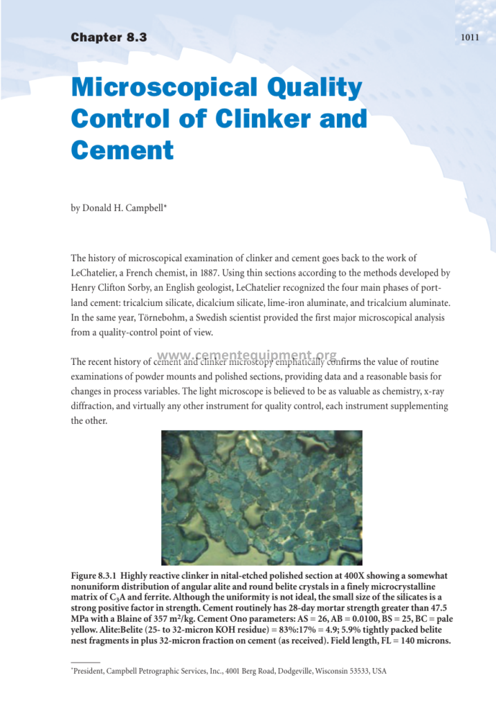
The recognition of the four principal clinker phases is the foundation of every microscopical examination. In a polished section etched with nital (one percent nitric acid in alcohol), the alite appears angular and dark-etched, the belite rounded, the aluminate and ferrite as the matrix in between; with different etchants their individual characteristics become sharper. The working identities are:
- Alite (tricalcium silicate, C3S): the main strength-giving phase, typically 55 to 70 percent of clinker, appearing in polished sections as angular, prismatic or lens-shaped crystals with sharply defined edges; its size is the Ono parameter AS (alite size).
- Belite (dicalcium silicate, C2S): typically 15 to 30 percent of clinker, appearing as rounded, rounded-polygonal or lath-shaped crystals, frequently with characteristic lamellar twinning; belite is less reactive than alite and contributes most of the later strength.
- Tricalcium aluminate (C3A): the aluminate phase, typically 5 to 10 percent, forming part of the interstitial matrix between the silicates, important for setting behaviour and sulfate response.
- Ferrite (tetracalcium aluminoferrite, C4AF): the iron-bearing phase, typically 5 to 15 percent, filling the matrix; its amount rises with the iron content of the raw meal.
- Free lime (CaO): uncombined lime, normal at 0.5 to 2.0 percent in the clinker, higher values signalling underburning, uneven burning or lime saturation that is too high; the microscope sees free lime as rounded white inclusions, and it is among the quickest and most useful readings available.
The practical lesson for the analyst is that the microscope reads the phases in their spatial and historical context. A clinker with angular, uniformly distributed alite in a fine-grained, well-crystallised matrix and round belite with good crystal habit has the textbook microstructure of a strong, well-burned clinker; a clinker with large, corroded alite crystals, aggregated belite and excessive free lime tells the opposite story. Because every one of these features is quantified by the Ono system, the plant can move from opinion to numbers.
3. Sample Preparation: Polished Sections for Reflected Light
Routine quality-control microscopy demands rapid and reproducible sample preparation, and the polished section is the workhorse of the method. The sequence for preparing a clinker polished section is well established:
- Clinker selection: take a representative sample of nodular clinker from the kiln discharge or cooler, including ideally the 5 to 7 millimeter fraction that is the standard of clinker inspection; crush the finest fraction and select a representative subsample.
- Impregnation: mount the clinker fragments in a low-viscosity epoxy resin under vacuum, so that porosity and cracks are filled and the section does not pop out during grinding; the resin also preserves the delicate structure of porous and reactive clinkers.
- Grinding: flatten and grind the mount on successively finer papers, typically 240, 400 and 600 grit abrasive, removing the saw damage and exposing a flat surface of the clinker fabric.
- Polishing: polish on cloths with diamond pastes of 3 microns and then 1 micron, optionally finishing with a very fine alumina or colloidal silica step; the aim is a scratch-free mirror surface that reflects light uniformly.
- Etching: etch the polished surface briefly with nital (one percent nitric acid in ethanol), or with other selective reagents, to bring out the phases; light or over-etching changes the appearance, so the etch time is learned against known standard specimens.
- Immediate examination: examine the etched section promptly, because the polish and etch degrade with time, and store the mount desiccated if re-examination is needed.
The preparation discipline determines the quality of everything that follows. A poorly polished section shows artifacts (scratches, relief, pull-outs, smearing) that are routinely mistaken for clinker features; the experienced analyst checks polish quality first and re-prepares when necessary. With practice, the complete cycle from clinker sample to polished section ready for examination takes well under an hour, which is what makes daily microscopical control practical in a busy plant laboratory.
4. The Ono Method: The Four Parameters and Their Interpretation
The Ono method transforms the visual impressions of the polished section into four numbers correlated with the burning conditions of the kiln and the hydraulic activity of the clinker. Each parameter responds to a different process variable: heating rate, peak temperature, burning time and cooling rate. The framework, with the values refined in the source chapter, is summarised in the table below.
| Parameter | Meaning / Process Variable | Excellent (rate 4) | Good (rate 3) | Average (rate 2) | Poor (rate 1) |
|---|---|---|---|---|---|
| AS – Alite size | Heating rate | 20-30 microns | 30-40 microns | 40-60 microns | over 60 microns |
| AB – Birefringence of alite | Maximum firing temperature | 0.010-0.008 | 0.008-0.006 | 0.006-0.005 | 0.005-0.002 |
| BS – Belite size | Burning time | 25-40 microns | 20-25 microns | 15-20 microns | under 15 microns |
| BC – Belite color | Cooling rate | Clear (C) | Faint yellow (FY) | Yellow (Y) | Amber (A) |
The interpretation logic reads like a diagnostic engine. Small angular alite (AS 20 to 30 microns) says the heating rate was rapid, which usually means a high-quality, kiln-condition-burn; large alite over 60 microns says slow heating, a sign of underburning or an overloaded kiln. High alite birefringence near 0.010 to 0.008 says the material reached a high maximum temperature; low birefringence near 0.005 to 0.002 says the firing temperature was low. Belite size between 25 and 40 microns with a clear color says long enough burning time at high temperature followed by rapid cooling; small amber belite says short burning time and slow cooling, the classic formation of the low-reactivity alpha-prime and beta belite with chromophores absorbing light. The combined reading gives a single quality verdict of the clinker’s hydraulic activity from excellent (4) to poor (1).
5. Microscopical Indices of Burning: Free Lime, Porosity and Matrix Condition
Beyond the four Ono parameters, the polished section carries several other readings that plant quality control uses daily:
- Free lime content: estimated by point counting the white rounded lime inclusions in the section; normal clinker contains 0.5 to 2.0 percent free lime, and readings above 2 to 3 percent flag underburning, raw meal segregation or an excursion in the lime saturation factor. The microscope gives the free lime answer in minutes, while the chemical titration takes the best part of an hour.
- Porosity and coating: an open, porous structure with abundant voids suggests a dusty or low-strength clinker and predicts poor flow and storage behaviour; heavy hole formation in grains signals volatile cycling and alkali- or sulfate-related disruption.
- Alkali sulfates and alkali compounds: visible as bright phases in the voids and on crystal surfaces, especially after proper etching; their distribution influences the reactivity of the cement and its compatibility with chemical admixtures.
- Matrix crystallinity: a finely microcrystalline aluminite-ferrite matrix, almost unresolvable at 400 magnification, is the signature of rapid cooling and reactive interstitial phases; a coarse matrix with large aluminate crystals says sluggish cooling and a less reactive set.
- Clinker reducibility and burning sense: the presence of metallic iron blebs and a darkened, low-reflectance fabric signals a reducing kiln atmosphere, which destroys the alite and produces the dark brown-black clinker the operators recognise as chemically reduced.
Each of these readings has a direct operational consequence. Free lime above target calls for an increase in burning temperature or a correction of the kiln feed composition. High porosity in the clinker changes the kiln feed and the flame shape. Reducing conditions in the kiln require oxygen correction at the burner. Abundant alkali sulfates change the sulphate balance of the cement and its setting behaviour. The microscope therefore functions as the kiln operator’s second set of eyes, converting the chemical history of the process into visible, actionable information several hours before the 28-day strength results arrive from the mortar lab.
6. Powder Mounts and the Microscopy of Cement Itself
In addition to the polished section of the clinker, the laboratory examines the cement itself as a powder mount, which is the fastest of all microscopical techniques. A small representative sample of the finished cement is dispersed in a liquid of known refractive index on a slide, covered and examined in transmitted light, often with crossed polars to see the birefringence of the crystalline phases. The powder mount answers questions that neither chemistry nor the residue sieves can address directly:
- Phase identification: the principal phases of the cement are identified by their refractive indices, birefringence and habit; alite and belite are distinguished from the aluminate and ferrite, and lime from gypsum.
- Free lime check: free lime in the cement appears as isotropic, rounded grains of high relief; a quick scan quantifies the free lime approximately and flags samples to be confirmed chemically.
- Gypsum and sulfate condition: the presence of unground gypsum, of hemihydrate from mill dehydration, and of developed gypsum crystals in stored cement can be recognised, giving early warning of setting problems and of false set.
- Grinding quality: the distribution of clinker sizes, the presence of agglomerates, and the ratio of fines to coarse particles in the mount give an immediate qualitative picture of the separator performance between laboratory checks.
- Additions verification: in blended cements, slag (glassy, angular, isotropic fragments), fly ash (spherical hollow spheres), limestone (clean calcite cleavage) and natural pozzolana are all readily identifiable in the mount, which makes the microscope a quick screen for the declared composition of composite cements.
The powder mount is the ideal complement to the polished section: the section reads the history of the kiln, the mount reads the state of the cement. Both techniques together give the laboratory a complete microscopical loop around production, from the clinker at the cooler to the finished product at the silo, at a cost of minutes and with no expensive consumables beyond the immersion liquids and slides.
7. The Heat Treatment Route: Quenching and Its Interpretation
An important refinement of clinker microscopy is the interpretation of deliberately quenched samples. When a sample of clinker is taken and allowed to cool in air, its belite changes color and its alite may corrosion-etch; when a sample is quenched rapidly, the state of the material at the moment of sampling is preserved and the Ono parameters can be read without the distortion of slow laboratory cooling. The distinction matters because the cooling rate in the sample route, not only in the production cooler, affects the readings.
- Sampling for Ono parameters: for reliable AS, AB, BS and BC values, the clinker should be sampled hot and quenched quickly, so that the belite color reflects the production cooler rather than the laboratory bench.
- Interpretation of belite color: the amber-to-clear scale of belite color is a thermometer of cooling; the plant that cools rapidly produces clear belite, the plant with a sluggish cooler or with clinker piles left hot shows yellow and amber belite with the corresponding reduction in hydraulic activity.
- Links to cement strength: the source chapter records cements with routine 28-day mortar strength greater than 47.5 MPa at a Blaine of 357 m2/kg whose clinker showed a highly reactive structure, demonstrating that the microscope readings and the mortar results track each other closely across the plant’s production range.
This heat-treatment discipline is what allows the microscopical parameters to be entered into process equations for quality control, exactly as Ono intended. The parameters have very high correlation coefficients with the measured strength and setting properties, which is why the Japanese kiln burners were trained to use the microscope routinely and why the modern plant can adopt the same practice: the microscope is a strength-testing instrument that works in minutes instead of months.
8. The Microscopy of Common Problems: What the Analyst Sees
Every plant engineer knows the recurring clinker problems, and each one has a characteristic microscopical signature that the experienced analyst recognises at a glance:
- Underburning: abundant free lime, small alite crystals with low birefringence, clustered belite and a coarse matrix; the clinker is dusty, legal and weak-limited, and strength margins shrink.
- Overburning: very large alite crystals (often over 60 microns) with alpha-dissolution cavities, blocky clear belite said to be well-formed, and low apparent porosity; overburned clinker is hard to grind and reacts slowly, wasting energy in the mill.
- Reducing kiln atmosphere: dark brown to black clinker fabric, corroded alite edges, metallic iron blebs and a characteristic dull reflectance; the kiln needs more oxygen and the raw meal may show high sulphur recirculation.
- Sudden coating and ring formation: liquid-phase flooding, incongruently melted phases and the presence of large irregular melt pockets in the section, with the alite partly dissolved and reprecipitated as fine crystals on the old surfaces.
- Slow cooling in the cooler: amber belite as the dominant belite color, coarse matrix phases and sluggish, glassy-looking interstitial material; the cooler fans and the clinker residence time are the suspects.
- Raw meal segregation: a heterogeneous clinker, some fragments with high free lime and others with burned-out, glassy structure, telling of feed that reached the kiln inhomogeneous despite the blending silo.
The power of these signatures is that they point to the cause, not only the effect. The analyst who reports “underburning with high free lime” directs the kiln operator to temperature; who reports “heterogeneous burning” directs attention to the raw meal system; who reports “reducing conditions” directs attention to the flame. This diagnostic orientation is what separates microscopical quality control from passive testing: the microscope participates in the process loop, not just in the paperwork.
9. Quantitative Microscopy: Point Counting and Phase Distribution
For rigorous work, the microscope becomes quantitative through systematic point counting. The analyst traverses the polished section on a regular grid or random line, identifying the phase under the cross-hair at each step, and accumulates counts until the statistics are adequate; the phase percentages follow directly from the counts. The traditional practice delivers:
- Phase composition estimates: alite, belite, aluminate, ferrite, free lime and void percentages for the clinker, directly comparable with the Bogue-calculated composition and with the Rietveld-refined X-ray diffraction results.
- Modal agreement with chemistry: discrepancies between the microscopical modal analysis and the chemical calculation are diagnostic in themselves: systematically high measured alite usually means the material is alkali- or sulfate-modified, where the Bogue deconvolution runs out of validity.
- Homogeneity assessment: running the point count on several fragments of the same sample quantifies the between-fragment variability, the microscopical measure of kiln feed and burning uniformity.
- Trend monitoring: booking the modal results daily and plotting them against free lime, litre weight and strength produces the correlation data that justify process changes with hard evidence.
Point counting is slower than the qualitative scan and is therefore used as a second-stage discipline: routine shifts use the quick scans and the Ono parameters, and the periodic deeper audits add the full modal analysis. The two speeds of microscopy mirror the two speeds of quality control in the plant: the fast loop of the daily operation and the slow loop of the monthly quality review.
10. Staffing, Training and the Integration With Other Quality Tools
Microscopical quality control lives or dies on the skill of the analyst, so the plant that adopts it seriously also invests in training and in the integration of the microscope with the other instruments of the laboratory:
- Training path: the analyst learns on standard reference clinkers whose phase identities and Ono parameters are known, practices preparation to a reproducible standard, and is periodically checked against the senior analyst’s readings on validation samples.
- Correlation with chemistry: the microscopical free lime is checked against the wet chemical free lime daily until confidence is established; thereafter the microscope serves as the rapid routine screen and chemistry as the referee.
- Correlation with X-ray diffraction: the modal phase percentages are compared with the Rietveld XRD results on the same clinkers; systematic differences between the two methods are themselves an item of information about crystal size, strain and amorphous content.
- Correlation with strength and setting: the Ono parameters are plotted against the 28-day mortar strengths and the setting times month by month, building the plant-specific calibration that gives the microscopic readings their authority in the control room.
- Documentation: standard examination forms record the Ono parameters, free lime estimate, qualitative fabric description and point-count results, with the sample identity and the kiln conditions at sampling time, keeping the whole history retrievable for audits and investigations.
The result is a working instrument hierarchy in the laboratory: the fast, cheap, information-rich microscope in the daily loop; chemistry and diffraction for the confirmation and the depth; and the mortar tests for the final legal and commercial confirmation. Each instrument supplements the others, exactly as the original authors of the method insisted, and together they give the plant a view of the process that no single technique could provide.
11. The Microscope in the Quality Loop: From the Cooler to the Dispatch Silo
The complete microscopical quality-control loop in a modern cement plant is a defined sequence of sampling and examination points that follow the process hour by hour:
- Cooler discharge sampling: hourly grab samples of clinker from the cooler discharge, quenched and examined on the polished section for the Ono parameters, free lime and fabric; the results are called to the kiln control room within thirty to forty minutes of sampling.
- Clinker storage and laboratory confirmation: the 5 to 7 millimeter sieve fraction of the clinker is inspected, and the microscopical readings are compared with the chemical free lime and the litre weight from the same hour.
- Kiln feed and raw meal checks: periodic examination of the raw meal and its residues keeps the incoming material in view; the microscope identifies unexpected constituents such as large quartz, organic matter and coarse refractory slag that the X-ray fluorescence sum may conceal.
- Finish mill input: the cement powder mount is examined at each shift change, checking the phase content, the gypsum condition, the fineness impression and the presence of agglomerates or foreign materials.
- Dispatch and complaint samples: every complaint sample and every market survey sample gets a powder mount examination as the first screening step, before the chemical and physical tests are unleashed.
This loop places the microscope at every material boundary of the plant. It is not an alternative to the central laboratory but an extension of it, and its particular strength is speed: the readings that shape the kiln decisions arrive while the kiln is still able to act on them, which is the whole point of the Ono philosophy that waiting for mortar strength results is no longer necessary.
12. Practical Requirements for the Plant Laboratory
Equipping the plant laboratory for microscopical control is modest in cost compared with X-ray fluorescence or diffraction instrumentation. The essential inventory is:
- A metallographic microscope: reflected-light microscope with objectives of 50 to 1000 times magnification (the 400 times objective being the working standard), polarising accessories, and a calibrated stage micrometer for crystal size measurement.
- Preparation equipment: a low-speed saw or breaker, a vacuum impregnation vessel with epoxy resin, a grinding and polishing machine with the abrasive papers and diamond pastes from 240 grit down to 1 micron, and an ultrasonic cleaner for the mounts.
- Etchants and reagents: nital (one percent nitric acid in ethanol) as the first-line etchant, distilled water for hydration chemistry studies, and the refractive index liquids for powder mounts.
- Imaging and archiving: a digital camera on the microscope, image capture software and an archive folder per kiln line, so that signatures can be compared visually across weeks and years.
- Reference collection: a set of calibration clinkers with known phases and Ono parameters, prepared once and kept as the standard against which etching time, polish quality and interpretation are keyed.
The total investment is an order of magnitude below the price of a diffractometer, and the return is the daily visibility of the burning process. For plants where the clinker quality varies with the fuel, the raw meal or the season, this visibility pays for itself repeatedly in the first compaign of kiln tuning.
13. Frequently Asked Questions
How long does a polished section take to prepare?
With practice, the complete cycle from clinker sample to ready-to-examine polished section takes less than one hour, and a skilled technician can run several samples in parallel. The steps are sample selection, epoxy impregnation, grinding on 240/400/600 papers, polishing with 3 and 1 micron diamond, etching with nital and examination. The reading itself takes minutes.
What does the alite size tell the kiln operator?
Alite size (the Ono parameter AS) reflects the heating rate of the kiln material. Alite of 20 to 30 microns signals rapid heating, normally a healthy burn; alite above 60 microns signals slow heating, often underburning or an overloaded kiln. Large alite predicts lower early strength and slower reaction, so the operator corrects temperature and feed rather than waiting for the mortar results.
Can the microscope replace chemical analysis or X-ray diffraction?
No: the microscope supplements them. Chemistry gives the bulk composition, X-ray diffraction gives the crystalline phases quantitatively, and the microscope gives the size, habit, distribution and condition of those phases, which neither of the other instruments sees. The three methods together are substantially more powerful than any one alone.
Why is belite color important?
Belite color (the Ono parameter BC, from clear through faint yellow and yellow to amber) is a function of the cooling rate: rapid cooling leaves clear, highly reactive belite, while slow cooling produces yellow to amber belite of reduced hydraulic activity. Amber belite in a clinker that should be clear tells the plant that the cooler is not doing its job.
How is free lime seen under the microscope?
Free lime appears in polished sections as rounded, white, isotropic inclusions, typically in the matrix between the silicate crystals. It is estimated by point counting or by comparison with calibration standards in minutes, giving a fast check that is normally confirmed chemically by the glycerol-ethanol or conductivity method when precision is needed.
Is the Ono method still used in modern plants?
Yes: the Ono parameters remain the standard quantitative framework of clinker microscopy, and they have been refined by later workers and combined with modern imaging and image analysis. Many plants report that the method works today exactly as it did at the Onoda Cement Company: it evaluates clinker immediately after production, prior to grinding, and gives a reliable preview of the strength and hydraulic activity the cement will deliver.
14. Conclusion and Summary
Microscopical quality control of clinker and cement is a mature, fast and information-dense discipline that has served the cement industry since LeChatelier and Tornebohm first read the phases in 1887 and reached its modern quantitative form in the Onoda school of the 1950s to 1970s. The polished section examined in reflected light reveals the burning history of the clinker: the alite size and birefringence report the heating rate and peak temperature, the belite size and color report the burning time and cooling rate, and the matrix, porosity, free lime and alkali phases complete the picture. The powder mount applies the same eyes to the finished cement, screening phase content, free lime, gypsum condition, grinding quality and the presence of additions in minutes.
The plant that adopts the discipline gains a quality instrument that works at the speed of the process, that reads the cause rather than only the effect of every excursion, and that correlates with the mortar strength results closely enough to steer the kiln and the mill with confidence. The light microscope is as valuable as chemistry and X-ray diffraction for quality control, each instrument supplementing the other, and the full documentation of the technique, including the Ono parameter tables, the preparation methods and the interpretation of high- and low-quality clinkers, is available in the Complete Cement Technical Package for the laboratory that wants to build or refresh its capability.
Get this cement file + the full 931-file package
$249.99 — one-time purchase, instant download, lifetime access
This file is part of the Complete Cement Technical Package (931 files) available from cementequipment.org. Respective rights holders; library copy for the licensed single user.