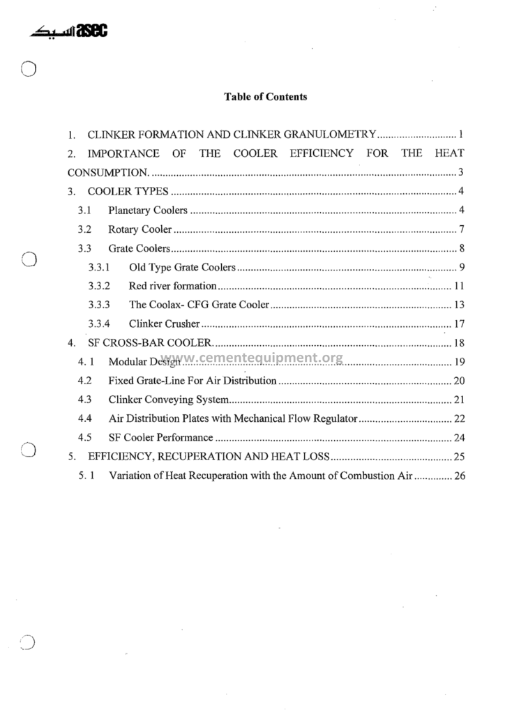
Cooler Systems: Complete Technical Guide
The cooler systems guide is the thermal and the mechanical manual of the clinker cooling: the file that explains how the clinker leaving the kiln at 1350-1450°C is cooled to 80-150°C in the grate machines, how the recovered heat returns to the process as the secondary and the tertiary air, and how the cooling rate decides the clinker microstructure and the cement quality: the cooler is the partner of the kiln: its efficiency moves the specific heat consumption by 50-150 kcal/kg and its availability moves the whole line: this guide is the complete course of the cooler: types, design, aerodynamics, heat recovery, quality effects and operations.
The Complete Cement Technical Package (931 files including the books, the courses, the Excel tools and the presentations: $249.99 one-time: instant download via the PayPal payment) includes the cooler guide with the design calculations, the airflow distribution chapters, the mechanical drawings and the operating manuals: this article walks the file: the cooler types and their comparisons, the grate and the airflow design, the heat recovery arithmetic, the clinker quality effects and the operating practice: the reader finishes with the complete picture of the cooling line and its role in the plant’s energy balance.
The clinker cooler is both a machine and a heat exchanger: mechanically it must move the 1200-1500 tons per day of hot clinker across a bed of 0.5-1.2 meters thickness without the bridges and the disruptions, and thermodynamically it must exchange the heat of the clinker into the combustion air with the efficiency of the modern machines: the two duties interlock in every design decision: the grate speed, the air volumes per compartment, the dead beds and the air pressures: this article follows the guide’s architecture: first what the cooler is, then how it recovers the heat, then how it is operated and repaired.
1. The Role of the Cooler in the Kiln Line: The Thermal Partner
The guide opens with the place of the cooler in the line, because the cooler’s purpose is only visible in the system context:
- The heat recovery function: the hot clinker carries 1,300-1,600 kJ per kilogram of the formation heat net of the process: the cooler returns the largest share of that heat to the kiln and the calciner as the preheated combustion air: the modern coolers recover the 70-75% of the sensible clinker heat, leaving 350-550 kJ/kg in the exhaust and the product streams;
- The secondary air: the kiln combustion air entering through the hood at 900-1100°C: the highest-temperature recovery of the cooler: the secondary air quantity of 0.7-1.0 Nm3 per kilogram of clinker, matching the kiln’s combustion needs:
- The tertiary air: the calciner air through the tertiary duct at 800-1000°C: the second hot recovery stream: together the secondary and the tertiary airs carry 55-70% of the recovered heat into the pyroprocess;
- The vent air: the excess cooler air that cannot enter the process leaves through the exhaust stack or the dedusting filter at 200-400°C: the vent air carries the remaining recoverable heat and is the target of the waste heat recovery systems;
- The quality function: the cooling rate decides the clinker mineralogy: the fast cooling freezes the alite in the small crystals and the glassy phase, the slow cooling degrades the cement strength: the cooler is a quality machine as much as an energy machine;
The introduction chapter establishes the two-sided nature of the cooler: the plant’s energy balance is incomplete without it, and the clinker quality is impossible without it: every later chapter of the guide returns to these two duties, and the operating practice keeps both in mind: the guide says the cooler is the unloved machine that holds the line together, and this file is its love letter in numbers.
2. The Cooler Types: The Evolution of the Machines
The guide presents the cooler families with their eras, their mechanisms and their performance numbers:
| Cooler type | Cooling mechanism | Typical heat recovery | Status |
|---|---|---|---|
| Rotary cooler | Rotating inclined cylinder with internal lifters, air or water cooling | Moderate, limited secondary air temperature | Historical, small plants |
| Planetary cooler | Satellite tubes around the kiln shell | High secondary air, no separate equipment | Historical, long dry kilns |
| Reciprocating grate cooler (1st gen) | Reciprocating grate plates moving the bed | 60-65% recovery | Older installed base |
| Modern reciprocating grate cooler | Reciprocating grate with the improved aeration | 70-75% recovery | Widely installed |
| Cross-bar cooler | Walking floor bars moving the bed over stationary aeration grates | 70-75% recovery | Modern lines and upgrades |
| Moving floor / roller grate coolers | Roller or moving floor transport | 70-75% recovery | Niche and modern applications |
- The reciprocating grate cooler: the classic machine: the rows of the grate plates reciprocate, pushing the clinker bed forward while the cooling air rises through the plates from the compartments below: the machine of the last fifty years, evolved through the generations of the airflow control: the installed base of the world’s cement lines is dominated by the modern reciprocating grate machines;
- The cross-bar cooler: the modern alternative: the transverse bars drag the clinker across the stationary aeration grate, so the air distribution is stable and the bed is aerated through the fixed gaps: the improved aeration uniformity, the reduced air requirement and the lower maintenance of the grate plates: the favorite of the new lines and the major upgrades;
- The planetary and the rotary coolers: the historical machines of the smaller and the older lines: the planetary tubes recover the heat without the separate cooler building but constrain the kiln design; the rotary coolers of the smallest plants: the guide documents them for the legacy plants and the historical understanding, while the modern practice concentrates on the grates;
- The comparison criteria: the heat recovery, the specific air consumption, the availability, the maintenance cost, the pressure drop and the footprint: the guide’s comparison matrix places the types against the plant size, the clinker characteristics and the modernization needs: the selection chapter of the file takes the reader through the decision from the plant’s own numbers;
The types chapter closes with the evolution insight: the cooler technology advanced from the simple drums to the aeration-optimized grates, and the progress measure is the recovery percentage and the air per kilogram of clinker: the modern machines reach the cooling air of 1.8-2.5 Nm3 per kilogram of clinker with the recovery of 70-75%, and the guide’s numbers place every machine generation on its curve.
3. The Aerodynamics of the Grate Cooler: The Air, the Bed and the Compartments
The grate cooler is an airflow machine, and the guide’s aeration chapter is the physics of the cooling bed:
- The bed behavior: the clinker bed of 0.5-1.2 meters thickness on the grate moves forward while the air rises through it: the fluidization threshold, the channeling through the coarse zones and the windrow formation at the grate edges: the bed uniformity is the master variable of the cooling quality, and the modern coolers control it with the bed height sensors and the controlled grate speeds;
- The compartment aeration: the grate is divided into the compartments of 1.5-3 meters length, each with its independent fan: the under-grate pressure of 4,000-8,000 Pa in the hot end, decreasing to 2,000-4,000 Pa toward the cold end: the air distribution of the compartments is the cooling recipe of the line: the fine-tuning of the air toward the clinker temperature profile across the grate length;
- The air-to-clinker ratio: the total cooling air of 1.8-2.5 Nm3 per kilogram of clinker in the modern machines: the air leaves as the secondary air, the tertiary air, the vent air and the product cooling losses: the air balance of the cooler is closed in the guide’s worksheets: every cubic meter is accounted between the process returns and the vent;
- The pressure drop of the bed: the bed resistance of 3,000-6,000 Pa depends on the clinker size distribution, the bed depth and the fluidization: the pressure drop measurements of the compartments are the operating window of the cooler: the rising drop at the constant air flow signals the bed compaction, the falling drop the clinker channeling or the grate plate wear;
- The dead bed and the starter bed: the layer of the stationary fine clinker on the grate that protects the plates from the burning clinker and distributes the air: the dead bed of 50-150 millimeters is maintained automatically by the air and the grate control: the dead bed failures expose the plates and the machine to the molten clinker: the guide’s dead bed control chapter is among the most practical of the operating sections;
The typical aeration numbers of a modern grate cooler are summarized in the table below:
| Aeration parameter | Typical value | Operating meaning |
|---|---|---|
| Bed thickness | 0.5-1.2 m | Uniform bed = uniform cooling and heat recovery |
| Compartments | 8-15, each with its own fan | Independent air recipe per grate section |
| Under-grate pressure, hot end | 4,000-8,000 Pa | High resistance of the dense burning clinker bed |
| Under-grate pressure, cold end | 2,000-4,000 Pa | Falling resistance toward the discharged clinker |
| Total air-to-clinker ratio | 1.8-2.5 Nm3/kg clinker | Modern coolers; the excess of 2.5 indicates the leaks |
| Bed pressure drop | 3,000-6,000 Pa | The operating window of the compartments |
| Dead bed thickness | 50-150 mm | Protects the plates and distributes the air |
The aeration chapter gives the reader the mental model of the cooler interior: the bed, the air and the pressure form one dynamic system, and the operating practice of the guide is written in that language: the compartment pressures, the air flows and the bed heights are the numbers the cooler operator lives with, and this chapter teaches them all.
4. The Heat Recovery: The Secondary Air, the Tertiary Air and the Exhaust
The recovery arithmetic of the cooler is the heart of its energy value, and the guide’s recovery chapter is the calculation course of the file:
- The recovery percentage: the ratio of the heat returned to the process to the sensible heat of the clinker entering the cooler: the modern grate coolers recover 70-75%, the older machines 60-65%: each percentage point of the recovery is worth roughly 8-15 kcal/kg of the specific heat consumption, and the guide’s sensitivity table quantifies the leverage exactly;
- The secondary air parameters: the kiln receives the secondary air at 900-1100°C and 0.7-1.0 Nm3/kg: the secondary air temperature is the first number of the cooler performance assessment: the secondary air temperature of the modern coolers is boosted by the hot end design: the guide’s assessment protocol measures the temperature and the flow to compute the recovery;
- The tertiary air parameters: the calciner air at 800-1000°C through the tertiary duct: the duct takes the air from the hot end of the cooler, commonly from the roof: the duct insulation and the false air of the duct reduce the delivered temperature: the guide’s tertiary duct chapter covers the insulation, the expansion joints and the pressure balance with the kiln;
- The vent air and the losses: the vented excess air at 200-400°C carries 15-25% of the clinker heat: the cooler shell losses, the product heat of the leaving clinker at 80-150°C and the false air of the casing complete the loss side: the guide’s loss breakdown table of a modern cooler shows where the un-recovered heat goes and what each loss line costs in the fuel;
- The waste heat recovery: the vent air and the tower exit gas feed the steam boilers and the ORC plants that generate the electricity: the waste heat recovery of the modern dry process lines produces 20-35 kWh of electricity per ton of clinker from the gas streams that would otherwise leave: the guide’s recovery systems chapter quantifies the electricity potential of the vent air specifically, and the economic papers of the package extend the analysis:
The recovery chapter closes with the complete heat balance of a modern cooler: the input clinker heat, the recovered streams, the losses and the efficiency: the reader learns to run the cooler audit with the measurements of the temperature, the flow and the composition: the audit is the instrument of every cooler improvement project, and this chapter is its manual.
5. The Cooler Sizing: The Grate Area and the Fans
The sizing of the cooler is the arithmetic of the guide’s design chapters, and the numbers are the plant engineer’s standard references:
- The grate load: the clinker throughput per unit of the grate area: the modern grate coolers of 35-55 tons per day per square meter on the total grate, with the hot-end sections working harder: the grate area of a 5000-ton-per-day line is 100-150 m2: the load governs the bed depth and the air distribution: the load tables of the guide match the cooler size to the clinker output;
- The cooling air volume: the fan fleet of 10-20 fans per cooler, each serving its compartment: the total air of 1.8-2.5 Nm3/kg at the working temperatures: the fan capacities of 50,000-200,000 Nm3/h per fan in the large coolers, with the static pressures up to 8,000-10,000 Pa at the hot end: the fan selection tables and the performance curves fill the design chapter;
- The temperature design points: the clinker enters at 1350-1450°C and leaves at 80-150°C; the secondary air zone reaches the equilibrium with the hot clinker; the vent air at 200-400°C: the temperature design points decide the casing materials, the expansion joints and the refractory of the hot end: the guide’s material selection tables serve the mechanical design;
- The kiln hood connection: the stationary hood connecting the kiln nose to the cooler with the sealing rings: the hood volume, the false air control and the burner access: the hood design of the guide covers the sealing against the kiln rotation and the puffs: the hood is the hot end where the secondary air is born, and its design decides the air temperature at the burner;
- The clinker transport: the hammer crushers and the rollers under the hot end that break the clinker lumps to the transportable sizes: the crusher duty of 1,500-3,000 tons per day with the wear parts of the hammers and the grates: the guide’s crusher section covers the selection, the wear and the spare parts management;
The sizing chapter of the guide walks the complete design of a cooler for the stated production: the grate area, the compartment count, the fans, the casing and the crusher: the reader who follows the worked example can check the design of a vendor offer and find the weak points: the sizing arithmetic is also the language of the upgrade projects, where the existing cooler is measured against the new production demand.
6. The Cooling Rate and the Clinker Quality: The Mineralogy Link
The guide’s quality chapter connects the cooler to the cement laboratory, and the link is the clinker microstructure:
- The phase formation: the clinker leaves the burning zone with the alite, the belite, the aluminate and the ferrite crystals grown at 1350-1450°C: the cooling decides the final crystal sizes: the fast cooling freezes the alite in the small needles and preserves the glassy phase, the slow cooling coarsens the crystals and allows the belite growth and the alite decomposition;
- The crystal size control: the cooling rate of 15-40°C per minute through the critical 1200-1300°C window determines the alite crystal size: the guide’s microscopy chapter shows the alite crystals of the fast-cooled clinker (10-30 micrometers) versus the slow-cooled clinker (40-100 micrometers) with the strength consequences: the fast-cooled clinker grinds easier and reacts faster with the water;
- The C3S content protection: the slow cooling through the 1250-1100°C range can partially decompose the alite into the belite and the free lime: the decomposition loss of the C3S lowers the clinker strength regardless of the burning: the cooling protection of the alite is the quality function of the rapid cooling in the hot end;
- The grindability: the cooling rate also decides the clinker’s response to the grinding: the fast-cooled clinker with the fine crystals and the glassy phase grinds 5-15% easier than the slow-cooled, saving the mill energy: the grindability index of the cooled clinker is measured and tracked in the plants, and the guide’s quality tables link the cooling practice to the mill kWh;
- The color and the consistency: the cooling atmosphere and the rate decide the clinker color: the reducing conditions at the cooling shift the iron phases and darken the clinker: the color consistency of the clinker is the visible quality indicator the operators watch: the guide’s color interpretation notes complete the quality chapter: the cooler’s product is judged by the eye before the laboratory confirms;
The quality chapter closes the two-sided picture of the cooler: the same machine that saves the heat also protects the strength: the guide’s message to the plant: the cooler setpoints are quality parameters, and the quality department and the production department read the same numbers: the fast cooling at the hot end is both the energy practice and the quality practice, one action with two beneficiaries.
7. The Cooler Operation: The Control Parameters of the Grate
The operating chapters of the guide teach the cooler as the control room sees it, and the parameter set is the daily life of the cooler operator:
- The bed height: the controlled bed level across the grate, measured by the bed height sensors or the weight of the sections: the target bed of 0.5-0.9 meters in the hot end, adjusted by the grate speed: the bed height is the primary variable balancing the cooling time and the air resistance;
- The grate speed: the drive speed of the grate or the moving floor, adjusted continuously to the clinker feed: the variable speed drives read the bed height and hold the material level: the grate speed control loop of the guide is the cooler’s equivalent of the kiln speed control;
- The compartment air flows: the air flow per compartment matched to the clinker temperature at that position: the hot end takes the most air (the deepest cooling duty), the cold end reduces the air: the air profiles of the guide give the starting distribution, and the operating practice tunes it to the actual clinker conditions;
- The under-grate pressures: the compartment pressures of 4,000-8,000 Pa at the hot end: the pressure readings diagnose the bed state: the stable pressures with the smooth bed, the fluctuating pressures with the clinker surfacing or the channeling: the pressure record of the day is the cooler’s diary, read in the guide’s troubleshooting chapter;
- The secondary air temperature: the control target of the hot end: the secondary air temperature rises with the effective cooling and the stable hood: the deviations signal the kiln changes before the kiln instruments show them: the guide’s early warning philosophy reads the secondary air temperature as the lookout of the line;
The operation chapter is written for the shift: the targets, the alarms and the responses: the guide’s operating manual is accompanied by the shift log formats and the parameter trend interpretations: the cooler operator of the modern plant watches the bed and the pressures the way the kiln operator watches the flame: the guide makes that watch teachable.
8. The Cooler Troubleshooting: The Snowmen, the Red Rivers and the Breakdowns
The cooler’s problems are famous in the industry and finite in number, and the guide’s troubleshooting chapter is the compiled field library:
- The snowmen: the fused clinker columns growing from the grate holes into the bed: the snowmen form when the fine and the sticky clinker sinters at the hot end and the air is insufficient: the symptoms: the rising under-grate pressure in the compartment, the falling air flow, the local overheating: the prevention: the stable burning, the correct dead bed, the adequate hot-end air; the removal: the air lancing and the manual breaking during the stops: the guide’s snowman chapter is the classic of the file;
- The red rivers: the molten clinker streams flowing over the grate when the sintering continues into the cooler: the red river melts the plates, burns the castables and disturbs the whole bed: the causes: the overheated kiln discharge, the clinker with the excessive liquid phase, the insufficient cooling air: the responses: the immediate air boost at the hot end, the kiln fuel reduction and the bed management: the red river is the emergency of the cooler, and the guide treats it with the respect of the danger;
- The clinker surfacing: the air channels through the coarse pockets and blows the fines off the bed in the fountains: the surfacing disturbs the air distribution and the cooling: the causes and the corrections of the bed non-uniformity: the aeration tuning of the compartments and the dead bed maintenance;
- The grate plate failures: the wear, the burning and the mechanical breakage of the plates: the damage signatures, the inspection intervals and the replacement campaigns: the plate spares of the guide’s stock lists and the repair scheduling between the kiln campaigns;
- The mechanical breakdowns: the grate drive failures, the hydraulic system problems of the cross-bar machines, the crusher jams and the sealing failures: the mechanical symptom tables of the guide connect each failure to the repair scope and the parts: the cooler availability record of the plant is reviewed in the guide’s reliability chapter with the benchmark values of 90-95% availability;
The troubleshooting chapter is the experienced crew’s knowledge made teachable: the snowmen, the red rivers and the surfacing each have their signatures in the pressures and the temperatures, and the guide’s decision trees take the operator from the symptom to the action in minutes: the cooler’s emergencies are survivable and manageable when the crew knows the library of the failures, and this chapter is that library.
9. The Cooler Maintenance: The Wear Parts and the Campaigns
The cooler consumes its wear parts in the abrasive service, and the maintenance chapters of the guide are the spare-part economics of the machine:
- The grate plates: the highest-wear component: the abrasion, the thermal stress and the mechanical load: the plate life of 18-36 months in the modern machines, shorter at the hot end: the replacement campaigns are planned with the kiln stops: the guide’s plate life tables map the wear by the compartment with the expected lives;
- The aeration gaps and the sealing: the air gaps between the moving parts and the stationary structures: the sealing strips and the side seals: the seal wear allows the air bypass and the pressure loss: the guide’s seal inspection schedules and the replacement criteria;
- The crusher wear: the hammer and the breaker plate wear of the hot-end crushers: the crusher availability in the 1,500-3,000 ton-per-day duty with the wear lives of months: the hammer reversal and the replacement planning of the guide’s crusher chapter;
- The hydraulic systems: the drives of the reciprocating and the cross-bar coolers: the hydraulic oil condition, the filters and the actuator seals: the hydraulic maintenance calendar of the guide with the oil sampling intervals and the system pressures;
- The refractory parts: the cooler hot-end castables, the bull nose and the side walls: the refractory campaigns of the cooler sections of 12-36 months, repaired in the kiln stops: the guide’s cooler refractory plans coordinate with the kiln relining campaigns, so the stops solve both machines at once;
The maintenance chapters close with the overall availability management: the cooler uptime records, the failure cause codes and the maintenance intervals: the guide’s reliability approach treats the cooler as the scheduled-maintenance machine, not the run-to-failure machine: the plants with the disciplined cooler maintenance hold the 90-95% availability that the line expects, and the file teaches the discipline with the checklists and the records.
10. The Cooler Modernization: The Upgrade Projects
The final technical chapters of the guide address the upgrade of the existing coolers, the most frequent project of the plant modernization:
- The modernization candidates: the older reciprocating coolers with the recovery of 60-65% and the high maintenance: the upgrade objectives: the recovery to 70-75%, the air reduction, the availability gain and the elimination of the snowmen: the project types of the guide: the full replacement with the modern machine, the hot-end replacement with the new grate sections, and the aeration upgrades of the existing compartments;
- The full replacement: the new cross-bar or the modern reciprocating cooler installed on the existing foundation where possible: the production gain of 5-15% from the improved cooling and the kiln stability, the recovery gain of 8-10 percentage points: the project scope, the duration and the payback arithmetic of the guide’s case studies;
- The hot-end upgrade: the new grate sections at the hot end with the improved aeration: the lowest-cost modernization that captures the largest share of the recovery gain: the guide’s hot-end upgrade examples quantify the saved kcal/kg and the improved secondary air temperature;
- The aeration improvements: the new fans, the variable speed drives and the compartment controls: the air reduction of 10-20% with the same cooling duty, paid in the fan electricity and the improved vent conditions: the guide’s air optimization projects are the fast-payback entries of the modernization menu;
- The project evaluation: the measurement campaign before the upgrade (the recovery audit of the existing machine), the design targets, the payback and the risk register: the guide’s evaluation framework is the same framework the upgrading-projects file of the package applies at the plant scale: the cooler project is the smallest and the most profitable member of the modernization family;
The modernization chapter closes the technical body of the guide with the economic argument: the cooler is the most concentrated opportunity of the plant’s heat balance: the modernization of the cooler returns the investment in the fuel savings and the production gains faster than almost any other project of the line, and the guide’s case tables show the payback windows of 1-3 years for the typical upgrades: the cooler that cools better heats better: the guide closes its teaching on that paradox.
11. The Cooler Instrumentation and the Control Loops: The Measurements of the Machine
The cooler of the modern line is instrumented like the kiln itself, and the guide’s instrumentation chapter lists the measurements that run the machine:
- The clinker temperature measurements: the bed temperatures across the grate by the thermocouples in the bed and the infrared scanners above the grate: the temperature profile of the bed is the master map of the cooling: the hotspots at the hot end and the uneven profiles announce the channeling and the snowmen before the pressures rise: the guide’s temperature map interpretation is the morning routine of the cooler engineer;
- The under-grate pressures: the pressure transmitters per compartment at 4,000-8,000 Pa: the pressure readings are the bed’s health signals, and the guide’s trend analysis teaches the reading of the compartment pressures as the diagnostic instrument: the rising pressure with the air constant means the bed compacting, the falling pressure the gaps and the channeling;
- The air flow measurements: the flow meters per compartment and the total air: the flow balance of the cooler against the process needs: the measured air volumes feed the recovery calculations and the fan control: the guide’s flow instrumentation uses the annubar and the orifice measurements with the calibration schedules;
- The secondary and the tertiary air temperatures: the thermocouples in the hood and the tertiary duct: the recovery performance numbers of the line: the guide’s measurement points and the accuracy requirements follow the recovery audit protocol of the energy chapters;
- The discharge temperature: the clinker temperature after the cooler, measured by the pyrometers and the probe systems at the discharge: the final quality gate of the cooling: the discharge temperature trend is the daily report number that the plant management tracks: the guide’s discharge measurement chapter covers the pyrometer selection and the emissivity corrections;
- The control loops: the bed height control (the grate speed loop), the compartment air control (the fan speed or the damper loops), the vent air temperature control and the kiln hood pressure control: the control philosophy of the guide cascades the temperature and the pressure loops into the stable machine operation: the loops are tuned for the interaction with the kiln and the calciner controls, because the cooler is the air supplier of both;
The instrumentation chapter closes with the data use: the cooler records integrated into the plant’s process data system, the trends archived and the daily summaries reported: the cooler measurements are the evidence of the recovery performance for the energy audit and the quality evidence for the clinker assessment: the instrumented cooler is the auditable cooler, and the guide’s data philosophy makes the records serve both the operation and the reporting: the numbers of the machine are the language of its management.
The cooler data archive also becomes the baseline of the improvement projects: the pre-modernization measurements (the temperatures, the air flows, the pressures and the recovery) are the starting line that the post-project measurements cross: the guide’s project documentation framework archives the baseline and the acceptance data of every cooler upgrade, so the investment decisions of the plant are confirmed by the measured results rather than the vendor promises: the same archive supports the annual energy audits, where the cooler recovery is compared year by year against the design and the degradation trends are caught early: the instrumented history of the cooler is the evidence currency of the plant, and the guide teaches the reader to mint it correctly.
12. The Frequently Asked Questions
What is the typical clinker temperature leaving the cooler?
The modern grate coolers discharge the clinker at 80-150°C, with the best machines approaching the 60-100°C range: the older coolers leave the clinker at 150-250°C: the discharge temperature is the visible summary of the cooling performance, measured at the transport conveyors and tracked in the daily reports: the target temperature of each plant depends on its cooler generation and its vent air capacity.
What is the secondary air temperature and why does it matter?
The secondary air is the kiln’s preheated combustion air drawn through the kiln hood: in the modern coolers it reaches 900-1100°C before entering the kiln: the temperature matters because each 100°C of the secondary air saves 3-6 kcal/kg of the specific heat consumption through the flame enthalpy: the secondary air temperature is the first indicator of the cooler recovery performance.
Why does the fast cooling produce the stronger cement?
The fast cooling preserves the alite in its small, reactive crystals and prevents its decomposition into the belite and the free lime during the slow passage through the 1100-1300°C range: the small alite crystals hydrate faster and develop the strength earlier, and the glassy phase contributes the early hydraulicity: the cooling rate is therefore a quality parameter, not only an energy parameter: the plants cool fast and grind easy.
What is a snowman in the clinker cooler and how is it avoided?
The snowman is the fused clinker column that grows from a grate hole into the bed when the fine sticky clinker sinters over the insufficient air flow: it restricts the air, rises the under-grate pressure and disrupts the cooling: the avoidance combines the stable kiln burning (the consistent clinker fineness), the controlled dead bed and the adequate hot-end air: the removal requires the lancing and the manual breaking at the stops: the snowman is the classic cooler failure, preventable and manageable.
How much electricity can the cooler vent air generate in the waste heat recovery?
The vent air at 200-400°C combined with the tower exit gas feeds the steam or the organic Rankine cycle plants that generate roughly 20-35 kWh of electricity per ton of clinker in the modern dry process lines: the cooler vent contributes its share of the usable gas streams: the exact number depends on the gas volumes, the temperatures and the cycle efficiency, and the guide’s recovery calculations size the systems.
13. Conclusion
The cooler systems guide is the complete course of the clinker cooling line: the machine types and their evolution, the aeration physics, the heat recovery arithmetic, the sizing, the clinker quality effects, the operations, the troubleshooting and the modernization: the engineer who studies the file can audit a cooler, tune its compartments, diagnose the snowmen and plan its upgrade: the cooling line of the plant is understood as the connected thermal and mechanical system it really is.
The cooler is the most accessible opportunity of the plant’s energy balance: its recovery is measured, its modernization is proven and its quality effects are immediate: the guide of the package puts the whole opportunity into the hands of the plant’s engineers: the Complete Cement Technical Package includes this file with the design tables, the airflow models, the operating manuals and the project evaluations among its 931 files, one-time $249.99, instant download via the PayPal payment: the cooling of the clinker, mastered: the partner of the kiln, understood and controlled.
Get this Cooler Systems guide + the full 931-file package
$249.99 — one-time purchase, instant download, lifetime access
This file is part of the Complete Cement Technical Package (931 files) available from cementequipment.org. Respective rights holders; library copy for the licensed single user.