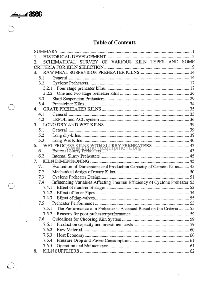
Kiln And Preheater Systems: Complete Technical Guide
The kiln and preheater systems guide is the central process file of the cement package: the manual of the entire pyroprocessing line: the suspension preheater tower with its cyclones and its calciner, the rotary kiln with its zones, its drive and its support, and the gas and the material paths that turn the raw meal into the clinker: the kiln line is the heart of the cement plant, the vessel where 1350-1450°C of clinker sintering happens and where the majority of the plant’s fuel is consumed: this guide is the complete course of that heart: the process chemistry, the equipment design, the mechanical systems and the operating practice.
The Complete Cement Technical Package (931 files including the books, the courses, the Excel tools and the presentations: $249.99 one-time: instant download via the PayPal payment) includes the kiln and preheater guide with the design calculation tables, the process diagrams, the mechanical drawings and the operating manuals: this article walks the file: the preheater stages and their temperatures, the calciner combustion, the kiln zones, the refractory, the drives, the alignment and the operations: the reader finishes with the complete picture of the line, from the raw meal at the top of the tower to the clinker at the cooler inlet.
The modern dry process line is the achievement of the last fifty years of the cement engineering: the five-stage preheater raises the raw meal to 820-870°C before it ever sees the kiln flame, the calciner completes 85-95% of the calcination outside the kiln, and the rotary kiln itself concentrates on the clinker sintering: the system is one continuous thermal machine whose stages depend on each other through the gas and the material flows: this article follows that machine stage by stage, with the temperatures, the pressures, the velocities and the residence times the file documents.
1. The Architecture of the Kiln Line: The Stages of the Pyroprocess
The guide opens with the line architecture, because every later chapter refers to the connected whole:
- The preheater tower: 4-6 cyclone stages stacked over the kiln inlet: the countercurrent heat exchange of the raw meal and the kiln gas: the top stage receives the cold meal and the warmest gas leaves at the top: the stage temperatures from 290-330°C at the top to 820-870°C at the bottom stage outlet;
- The calciner: the combustion chamber between the kiln inlet and the lowest cyclone: where 55-65% of the total fuel burns in the meal-dense gas at 840-900°C: the calcination degree of 85-95% is achieved here before the kiln inlet;
- The rotary kiln: the inclined rotating vessel 3-6 meters in diameter and 40-90 meters long, rotating at 2.5-4.5 rpm with a slope of 3.5-4%: the vessel where the remaining calcination completes and the clinker minerals form at 1350-1450°C;
- The kiln burner: the firing system at the discharge end: the flame of 1800-2000°C delivered through the modern multichannel burner: the heat source of the entire line;
- The hood and the nose ring: the discharge end connection to the cooler: the gas and the clinker leave the vessel here: the secondary air from the cooler enters the kiln through the hood at 900-1100°C;
- The connections: the kiln inlet chamber, the riser duct, the tertiary air duct from the cooler to the calciner, and the transition pieces: the gas path joins the tower to the kiln and the cooler into one system;
The architecture chapter of the guide marks every junction of the gas and the meal flows with its typical temperature and pressure, so the reader builds the mental model of the line before the deep chapters: the model is the map on which the whole file is drawn: the guide returns to this map in every balance and every troubleshooting case.
2. The Suspension Preheater: The Cyclones and the Gas-Solid Heat Exchange
The preheater tower is the heat exchanger of the line, and its design is the arithmetic of the countercurrent gas and meal flows:
- The cyclone stages: each stage is a gas-solid separator: the meal is dispersed into the hot gas, exchanges the heat in the duct, and is separated in the cyclone: the cycle repeats stage by stage: the raw gas temperature drops from 1050°C at the kiln inlet to 290-330°C at the tower exit in the five-stage lines, and to 260-290°C in the six-stage lines;
- The stage temperature ladder: the typical five-stage profile: the top stage gas at 290-330°C, the second at 450-500°C, the third at 600-650°C, the fourth at 730-780°C, the lowest at 830-870°C: the meal leaves the lowest stage at 820-850°C, already 5-15% calcined by the kiln gas;
- The heat exchange efficiency: the suspension heat exchange is the fastest in the industry: the meal particles of 20-100 micrometers exchange the heat in 1-2 seconds of the duct residence: the cyclone itself does not exchange heat, the duct does: the stage efficiency concepts of the guide quantify the ideal versus the actual gas-meal equilibrium;
- The cyclone separation: each cyclone collects 92-97% of the meal in the modern geometries, and the collected meal passes to the next stage duct where the fresh dispersion occurs: the separation loss means the meal recirculation and the heat loss, so the cyclone geometry, the inlet velocities of 15-22 m/s and the dip tube design matter to the balance;
- The pressure drops: each stage holds its pressure drop of 4-8 mbar, the total tower of 30-50 mbar: the rising drop of a stage signals the blockage building, the falling drop the gas short-cut or the cyclone wear: the ID fan of the line is sized for the total drop with the headroom for the fouling;
The preheater chapter carries the complete stage calculations: the gas velocities, the cyclone diameters, the duct lengths, the drop legs and the flap valves: the engineer who works through the design tables of the file can audit an existing tower and specify a new one: the guide’s worked example sizes a five-stage tower for a 5000-ton-per-day line, with the cyclone dimensions and the fan duties.
3. The Calciner: The Second Combustion Chamber
The calciner is the innovation that defines the modern kiln line, and the guide gives it the chapter its importance deserves:
- The calcination reaction: CaCO3 → CaO + CO2: the endothermic decomposition absorbing 1780 kJ per kilogram of CaCO3: the reaction rate becomes significant above 700°C and completes in the calciner environment of 840-900°C within the 1-3 seconds of the gas residence;
- The calciner types: the inline, the offline and the split calciners: the inline sits in the riser duct between the kiln exit and the lowest cyclone, the offline has its own cyclone pair and its own gas path, the split distributes the fuel and the air in stages: each type has its NOx behavior and its fuel flexibility, documented with the diagrams in the guide;
- The fuel and the air in the calciner: 55-65% of the total line fuel burns here: the tertiary air at 800-1000°C enters from the cooler through the tertiary duct: the staged air injection creates the reducing zone that destroys the NOx formed in the kiln: the fuel burns in the atmosphere rich in the CO2 from the calcination, which lowers the flame temperature and the NOx formation:
- The meal distribution: 60-70% of the raw meal is fed into the calciner, the rest to the riser duct: the meal to the calciner cools the flame and absorbs the calcination heat: the distribution ratio is an operating variable the guide tunes with the calcination degree measurements;
- The calcination degree: the modern lines leave the lowest cyclone with 85-95% of the calcination done: the kiln then performs the clinkering with a moderate heat duty and the shorter residence: the kiln-specific heat release falls, the kiln output per cubic meter of the shell volume rises, and the production of the modern lines reaches 1.0-1.4 tons per day per cubic meter of the kiln volume;
- The calciner risks: the catch-fire from the meal deposits in the corners, the afterburning in the cyclones when the fuel survives the calciner, the CO peaks when the air is sub-stoichiometric: the riser duct CO and O2 measurements guard the operations, and the guide’s risk chapter details the measures;
The calciner chapter closes with the design velocities: 12-18 m/s in the riser duct gas, the calciner residence of 1-3 seconds, the fuel burnout requirements of the alternative fuels: the chapter is the bridge between the preheater chapters and the kiln chapters, exactly as the calciner is the bridge in the process itself.
4. The Rotary Kiln: The Vessel and Its Process Zones
The rotary kiln is the iconic vessel of the cement industry, and the guide’s chapters cover it from the shell metal to the coating:
- The kiln dimensions: the modern precalciner kilns of 3.5-5.5 meters inner diameter and 45-85 meters length: the length-to-diameter ratio of 10-16 for the dry process vessels: the shell of 25-80 millimeters of the steel plate with the tires and the supporting piers every 10-15 meters;
- The kiln slope and the speed: the slope of 3.5-4% (about 2-2.3 degrees) and the rotation of 2.5-4.5 rpm: the material progresses through the kiln by the rolling of the bed, with the residence time of 20-40 minutes: the bed moves by the combination of the rotation, the slope and the internal friction, and the guide devotes its kinematics section to the bed behavior;
- The process zones: the calcination zone at the inlet (the last 10-20% of the calcination completes here at 850-1000°C), the upper and the lower transition zones (1000-1250°C and 1250-1350°C), the burning zone (1350-1450°C), and the discharge zone near the nose: each zone has its heat duty, its coating behavior and its refractory grade, mapped on the longitudinal section of the guide;
- The filling degree: the kiln is filled to 10-13% of its cross-section with the clinker bed: the loading (the clinker weight per kiln volume) of the modern lines is 1.0-1.4 tpd per cubic meter, and the guide’s loading calculations follow the standard design practice;
- The heat transfer zones: the radiation dominates in the burning zone where the flame at 1800-2000°C radiates to the bed and the refractory; the convection and the conduction share the heat duty in the calcination zone; the guide’s heat transfer chapters quantify each mechanism with the emissivity and the radiation constants;
The kiln process chapter is the core of the guide: the reader learns to read the vessel as the sequence of the chemical stages, each with its temperature window and its quality consequences: the free lime, the alite size and the clinker microstructure are all decided here, and the guide ties the process parameters to the final clinker quality in the tables of the chapter.
5. The Kiln Mechanical Systems: The Drive and the Alignment
The rotation of the kiln is delivered by the drive systems that are the mechanical heart of the vessel, and the guide covers the complete drivetrain:
- The drive arrangements: the girth gear and the pinion drive on the modern kilns, with the auxiliary drive for the slow rotation during the stops: the main drive motors of 300-1200 kW depending on the kiln size: the drive power of the kilns is about 0.4-0.8 kW per ton per day of production, and the guide’s power calculations follow the standard formulas with the friction and the lifting components of the bed;
- The girth gear and the pinion: the girth gear of 5-7 meters diameter mounted on the shell flange, the pinion driven through the reduction gearbox: the tooth lubrication with the spray systems, the alignment of the gear mesh and the backlash control: the gear inspection intervals of the guide’s maintenance chapter;
- The tyres and the rollers: the hot-running tyres mounted on the shell at 10-15 meter spacing, each seated on the two support rollers mounted on the piers: the surface velocities of the tyres and the rollers of 40-60 meters per minute, the roller bearings with the oil lubrication and the temperature monitoring;
- The thrust and the axial control: the kiln is held in the axial position by the thrust rollers against the slight down-hill creep: the hydraulic thrust devices of the modern kilns control the position with the sensors: the axial creep of millimeters per rotation is the observable health of the alignment;
- The ovality: the shell deforms under the load into the out-of-roundness: the ovality measurements of 0.2-0.8% of the diameter at the piers are the standard health numbers, and the excessive ovality damages the refractory and the shell: the guide’s ovality chapter links the mechanical measurements to the lining life;
The mechanical chapters of the guide are the maintenance engineer’s core: the drive, the alignment, the shaft deflections and the foundation behavior are presented with the inspection schedules and the acceptance criteria: the kiln that rotates smoothly in its alignment wears its refractory evenly and shows the long campaigns: the guide teaches the conditions of that smooth rotation.
And the vessel rotates truly only when it is aligned: a kiln is only as good as its alignment, and the guide’s alignment chapter is one of its most practical sections:
- What alignment means: the centerline of each pier must lie on the straight line within the tolerances of a few millimeters: the horizontal and the vertical deviations of the shell axis from the design line create the unequal loads on the tyres, the rollers and the shell: the alignment survey measures the pier heights, the roller positions and the shell centerline;
- The survey methods: the classical theodolite surveys and the modern optical and laser systems: the measurements of the pier settlements, the roller wear diameters and the shell profile: the survey frequency of every 2-5 years or after the notable foundation events: the guide’s survey protocol lists the measured variables and the report format;
- The roller adjustments: the realignment is performed by shimming and moving the rollers: the adjustment of a roller by tenths of a millimeter moves the local shell deflections by the measured amounts: the interaction between the piers makes the alignment an iterative discipline, learned in the guide’s worked adjustment cases;
- The shell deformation diagnosis: the misalignment symptoms: the uneven tyre temperatures, the unequal bearing loads, the shell cracks at the predictable locations, the refractory life differences around the circumference: the guide’s diagnosis table maps the symptoms to the misalignment types;
- The pier and the foundation: the foundation settlement monitoring with the survey marks, the spring-supported piers of the modern designs: the foundation behavior over the plant life is a measured history, and the guide recommends the permanent survey marks with the annual readings;
The alignment chapter closes with the economics: the aligned kiln shows the 10-30% longer refractory campaigns, the even thrust and the shell free of the fatigue cracks: the alignment service is cheap compared to the kiln stop it prevents: the file’s message is the maintenance master’s message: the straight kiln is the profitable kiln.
6. The Kiln Internals: The Chains, the Dams and the Coating
Inside the shell, the kiln is fitted with the internals that shape the heat transfer and the material flow:
- The chain systems: the chains hung in the wet and the long dry kiln inlets to enhance the heat transfer and the dust capture: the chain sections of the wet kilns with the hundreds of chains and the curtain arrangements: the guide’s chain design chapter covers the cross, the garland and the curtain systems with their heat transfer coefficients;
- The dams and the retention: the annular dams of the refractory or the castable at the discharge end that retain the deeper bed in the burning zone: the dam heights of 300-600 millimeters in the modern kilns: the deeper bed improves the heat absorption and adjusts the residence time: the dam design and the wear monitoring of the guide;
- The coating: the layer of the clinker and the dust that adheres to the refractory of the burning zone: the coating of 50-200 millimeters protects the brick from the flame and insulates the shell: the coating stability is the operator’s goal: the coating is held by the stable burning zone temperature of 1350-1450°C, the stable chemistry and the moderate rotation: the coating loss is the refractory’s death warrant, and the guide’s coating chapter teaches the formation and the retention;
- The rings and the build-ups: the clinker rings before the burning zone and the sulfate-alkali rings at the feed end: the ring growth narrows the kiln, disturbs the bed and forces the shutdown: the ring formation chemistry (the liquid phase, the return dust, the sulfur cycles) and the removal methods (the ring blasting, the flame adjustment) fill a full section of the file;
- The material flow behavior: the bed rolling, the segregation and the dust entrainment in the gas: the material transport correlations of the guide compute the residence and the filling from the kiln parameters, and the same correlations serve the process models of the package’s Excel tools;
The internals chapter is the operator’s part of the kiln knowledge: the chains, the dams and the coating are the tools the crew manages between the mechanical limits, and the guide’s operating rules translate the physics into the daily practice: the coating is watched, the rings are hunted and the dams are maintained, each with the indicators and the responses the file documents.
7. The Gas Flow and the Fans of the Line: The Pressure Architecture
The kiln line breathes through its fan and pressure systems, and the guide covers the gas side completely:
- The induced draft system: the ID fan at the tower exit draws the gas through the whole line: the fan of 3000-10000 kW in the modern large lines, handling the gas volumes of 1.0-2.0 Nm3 per kilogram of clinker: the fan static pressure of 6000-9000 Pa depending on the tower stages and the filter;
- The pressure profile: the kiln inlet chamber runs at a slight negative pressure of -50 to -150 Pa to prevent the puffs at the hood, the tower stages take their drops and the filter and the duct losses complete the curve: the fan inlet at -5000 to -7000 Pa: the guide’s pressure profile diagram places every measuring point on the line;
- The kiln exit gas volume: the gas volume at the kiln exit is 1.3-1.6 Nm3/kg clinker in the modern precalciner lines: the calciner adds its combustion gas and the calcination CO2: the tower exit gas of 1.45-1.75 Nm3/kg with the excess air: the gas volumes decide the tower and the fan sizing, and the guide’s gas volume calculations are the foundation of the whole design chapter;
- The false air: the leaks at the hood, the tower inspection doors and the duct flanges add the cold air that lowers the temperatures and raises the volumes: the false air of the operating kiln lines typically 5-15% of the gas flow, paid in the fan energy and the tower heat: the guide’s false-air pressure test procedure locates the leaks and quantifies the penalty;
- The fan control: the variable speed drives and the inlet vanes control the ID fan and the cooler fans: the fan efficiency operation of the guide’s energy chapter keeps the gas volumes at the exact line demand: the fan is the largest electricity consumer of the pyroprocess, and its control is an economic discipline;
The gas flow chapter is where the line’s energy economy is decided: the gas volumes are the denominators of all the specific consumptions, and the guide takes the reader through the full gas balance: from the fuel stoichiometry to the fan motor, every cubic meter is accounted and every saving is quantified: the pressure and the flow instrumentation of the line is described in the matching chapter at the same depth.
8. The Kiln Operation: The Control Parameters and the Daily Practice
The operating chapters of the guide teach the kiln as the control room sees it: parameters, setpoints and response:
- The key parameters: the kiln feed rate, the fuel rate, the burning zone temperature (read by the optical pyrometer and the shell scanners), the kiln exit gas temperature of 850-1050°C, the kiln exit O2 of 1.5-2.5%, the CO below 300 ppm, the kiln current and the free lime of the clinker: the parameter list of the guide with the target windows and the alarm values;
- The burner control: the flame shape management through the axial and the swirl air pressures, the burner tip position and the primary air rate: the flame response to the clinker quality: the free lime rising signals the cooler flame or the feed excess, the clinker falling out molten signals the overheating:
- The transient operations: the startup sequence (ring formation watch, the slow ramp), the shutdown (the ring removal by the flame, the clean burning), the feed interruptions and the fuel switchovers: each transient has its operating recipe in the guide, learned from the hard experience of the industry;
- The coating management: the daily coating watch with the shell temperature scanner: the hot spots identification and the actions: the shell temperature limits of 250-350°C in the normal operation with the alarms at 380-400°C: the scanner records of the guide map the refractory condition month by month;
- The quality control loop: the free lime analysis every shift, the clinker microscopy weekly and the SO3 balance continuous: the operating response to the quality drifts: the burning zone temperature correction, the fuel change or the feed chemistry adjustment: the guide’s quality-operation tables connect the symptoms to the parameters;
The operation chapter is written as the shift engineer’s handbook: the parameters, the setpoints, the alarm philosophy and the response sequences: the reader who studies it can follow the control room logic of any modern kiln, and the guide’s case studies replay the classic shifts: the ring removal night, the calciner trip and the feed break, each with its control room dialogue reconstructed.
9. The Kiln Refractory: The Armor of the Vessel
The refractory protects the shell from the 1450°C of the process, and the guide presents the lining practice completely:
| Kiln zone | Temperature | Typical lining | Campaign life |
|---|---|---|---|
| Burning zone | 1350-1450°C | Magnesia-spinel bricks (90-97% MgO) | 8-15 months |
| Lower transition | 1250-1350°C | Magnesia-spinel or magnesia-chrome-free basic bricks | 10-18 months |
| Upper transition | 1000-1250°C | High-alumina bricks (60-70% Al2O3) | 12-24 months |
| Calcination zone | 850-1000°C | High-alumina and insulation composite linings | 2-4 years |
| Kiln inlet and riser | 850-1100°C | Castables and alumina-based refractory concrete | 2-4 years |
- The brick families: the magnesia-spinel bricks of the burning zone with the thermal conductivity of 3-6 W/mK and the service limits above 1700°C, the high-alumina bricks of the transitions with the 60-70% Al2O3, the castables and the plastics for the non-cylindrical parts: the selection logic of each zone in the guide’s tables;
- The installation: the ring methods, the expansion allowances of 8-12 mm per meter, the mortar and the keying: the quality of the installation decides the campaign, and the guide’s installation chapter covers the brick-laying discipline, the curing of the castables and the drying schedules;
- The wear mechanisms: the chemical attack of the alkalis, the sulfates and the chlorides, the thermal cycling, the mechanical stress of the ovality, the abrasion of the sliding bed and the coating loss: each mechanism has its brick damage signature, and the guide’s failure analysis chapter teaches the identification from the shell inspection photos;
- The shell thermal monitoring: the infrared scanners along the kiln give the continuous shell temperature map: the rising shell temperature signals the lining thinning: the hot spot actions (the flame shortening, the feed adjustment, the cooling air) and the brick replacement planning: the temperature records of the guide become the campaign planning data;
The refractory chapter closes with the economics: the refractory cost per ton of clinker is a budget line the plant tracks, and the guide’s campaign benchmark tables show the best practice numbers: the stable coating, the correct brick grades and the honest installation pay in the campaign lengths, and the file teaches all three.
10. The Comparison of the Kiln Lines: From the Wet Process to the Six-Stage Precalciner
The guide compares the generations of the kiln systems, because the modernization decisions of the plants are made on these numbers:
| Line type | Heat consumption kcal/kg | Kiln exit gas temp | Calcination at kiln inlet | Relative production per kiln volume |
|---|---|---|---|---|
| Wet process | 1,200-1,500 | 200-400°C (slurry drying) | Not applicable | 1.0 |
| Long dry kiln | 900-1,100 | 800-900°C | Partial | 1.5 |
| 4-stage precalciner | 800-900 | 380-420°C at tower exit | 85-95% | 2.5-3.0 |
| 5-stage precalciner | 700-800 | 290-330°C at tower exit | 85-95% | 2.5-3.0 |
| 6-stage precalciner | 660-760 | 260-290°C at tower exit | 85-95% | 2.5-3.0 |
The comparison table is the summary of the process evolution: each stage added to the tower extracts more heat from the gas, and the fifth and the sixth stages are the standard energy instruments of the modern lines: the wet process survives only where the raw materials are wet by nature: the guide’s modernization chapter later builds on this table, because every upgrading project starts from the numbers of the existing line.
11. The Kiln Line Energy: The Heat Balance and the Efficiency Levers
The guide’s energy chapter is the accounting of the thermal performance, and it feeds the heat balance file of the package:
- The heat inputs: the combustion heat of the fuel and the sensible heat of the preheated combustion air, the meal and the fuel: the input side of every balance, dominated by the fuel: the specific heat consumption of the five-stage line of 2,950-3,350 kJ/kg (700-800 kcal/kg);
- The heat outputs: the clinker formation heat (theoretical about 1,750 kJ/kg), the evaporation of the raw material moisture, the sensible heat of the clinker leaving the cooler, the tower exhaust heat, the shell radiation and convection losses, the dust losses and the incomplete combustion losses: the output side of the guide’s balance tables;
- The exhaust gas loss: the single largest controlled loss at 19-23% of the input in the five-stage lines: the gas leaves at 290-330°C with the valuable heat: the sixth stage reduces the loss, and the waste heat recovery systems monetize the remainder: the guide quantifies each stage’s contribution in the saved kilojoules;
- The shell losses: 3-6% of the input radiated and convected from the shell: the insulation thickness, the scanning records and the weather: the cold kiln shell is the friend of the heat balance and the enemy of nothing else, within the coating limits;
- The efficiency levers: the lower excess air (each percent of O2 at the kiln exit costs roughly 1-1.5% of the heat input in the exhaust), the higher calciner share of the fuel, the cooler efficiency, the sixth stage addition and the moisture reduction of the feed: the lever-by-lever savings table of the guide is the project list of the modernization chapters;
The energy chapter closes the technical loop of the kiln line teaching: the process chemistry, the equipment and the operation all meet in the heat balance, and the balance is the language in which the plant discusses its performance with the consultants and the authorities: the guide makes the reader fluent in that language with the worked balance of a complete five-stage line.
12. The Troubleshooting of the Kiln and the Preheater: The Symptom Library
The guide’s final technical chapters are the compiled experience of the line: the symptom library the operator and the engineer consult when the line misbehaves:
- The preheater blockages: the cyclone and the riser blockages from the alkali-sulfate build-ups, the overfeed of the fine meal and the condensation: the symptoms: the rising stage pressure drop, the rising tower exit temperature, the ID fan surging: the cleaning measures: the air cannons, the doors, the shutdown cleaning: the guide’s blockage diagnosis tree leads the reader from the symptom to the action;
- The calciner problems: the afterburning in the lowest cyclone, the feed distribution imbalance, the fuel carryover: the temperature and the CO signatures in the riser duct: the correction strategies of the fuel split and the air staging;
- The kiln rings: the development, the growth rates and the removal: the ring type identification from the position and the chemistry (the sulfate rings near the inlet, the clinker rings before the burning zone): the flame and the speed adjustments that remove the rings gradually;
- The coating collapse: the sudden cooling of the shell in the burning zone after the coating falls: the shell temperature rise, the refractory distress and the emergency actions: the guide’s response sequence prevents the brick damage at the critical hours;
- The kiln puffing: the pressure pulses at the hood when the kiln discharge gas surges: the causes (the ring collapse, the feed piling) and the hood sealing practice: the puffing is uncomfortable and dangerous, and the guide’s chapter treats it with the respect of the safety matter;
- The mechanical problems: the kiln ovality, the shell cracks at the tyre edges, the gear wear, the roller bearing heating: the mechanical symptom library of the guide connects each sign to the measurement and the repair scope: the kiln’s mechanical health is the foundation that the process chapters stand on;
The symptom library is organized like the diagnostic manual: symptom, cause table, measurement, response: the reader who meets an unfamiliar disturbance finds its chapter in minutes and enters the shift with the plan: the guide’s experience collection is the accumulated practice of the industry, presented honestly as the field knowledge rather than any single author’s invention: the kiln’s troubles are finite, and the file lists them all.
13. The Frequently Asked Questions
What is the difference between the calciner and the kiln in the calcination duty?
In the modern precalciner lines, 85-95% of the calcination happens in the calciner before the raw meal enters the kiln: the calciner burns 55-65% of the fuel at 840-900°C in the meal-rich gas and completes the decomposition there: the rotary kiln then concentrates on the clinker sintering at 1350-1450°C, which shortens the kiln, lifts the production per kiln volume and reduces the refractory duty compared to the kilns where all the calcination happened inside the vessel.
Why do the modern kilns have five or six preheater stages?
Each stage recovers the heat from the kiln gas: the five-stage tower leaves the gas at 290-330°C and the six-stage at 260-290°C, versus the 380-420°C of the four-stage tower: the extra stage saves roughly 80-110 kcal/kg of specific heat consumption: the limit is the dew point of the tower exit gas: the acid condensation below about 200°C restricts the tower exit temperature, and the stage count is balanced against the sulfur and the moisture of the fuel and the feed: the sixth stage pays when the alternative fuels and the low-sulfur feeds allow it.
What is the typical burning zone temperature and how is it measured?
The clinker bed in the burning zone must hold 1350-1450°C for the alite formation: the gas temperature above the bed reaches 1700-1900°C under the flame: the temperature is measured indirectly: the optical pyrometers read the flame and the clinker color, the shell scanners read the refractory condition, and the free lime analysis of the clinker confirms the effective burning: no direct measurement exists inside the 1450°C bed, and the kiln operator triangulates the temperature from all the instruments and the clinker appearance.
How often must the kiln be aligned?
The recommended alignment survey interval is 2-5 years, or when the mechanical symptoms appear: the uneven tyre temperatures, the roller bearing loads or the shell crack indications: the annual control of the survey marks is the cheap insurance, and the full survey with the roller adjustments follows the measurements: the aligned kiln is the prerequisite of the even refractory wear and the 10-30% longer campaigns the guide quotes from the industry practice.
What is the residence time of the material in the rotary kiln?
The clinker material spends 20-40 minutes inside the vessel, depending on the kiln length, the slope, the speed and the filling: the residence time is computed by the standard material transport correlations from the rotation and the slope, and the guide’s Excel tool performs the calculation: the residence time must be sufficient for the alite formation and the clinker growth, and the modern kilns tuned for the maximum output watch the residence closely at the high fillings of the precalciner operation.
14. Conclusion
The kiln and preheater systems guide is the complete map of the pyroprocessing line: the preheater stages, the calciner, the rotary kiln, the drive and the alignment, the internals and the coating, the gas flows and the fans, the operations and the troubleshooting: the engineer who studies the file holds the entire vessel in his head, from the raw meal falling into the top cyclone to the clinker leaving the nose ring: the same engineer can audit a line, plan a modernization and read the control room logic of any kiln in the world.
The kiln line is where the cement plant earns its margin: the heat consumption of the clinker dominates the energy cost, and the availability of the line decides the annual production: the line that is understood is the line that is controlled, and the guide of the package exists to make that understanding complete and transferable: the Complete Cement Technical Package includes this file with the design tables, the mechanical drawings, the operating manuals and the calculation tools among its 931 files, at the one-time price of $249.99 with the instant download via the PayPal payment: the kiln and the preheater, mastered: the heart of the cement plant, in the hands of its engineers.
Get this Kiln and Preheater Systems guide + the full 931-file package
$249.99 — one-time purchase, instant download, lifetime access
This file is part of the Complete Cement Technical Package (931 files) available from cementequipment.org. Respective rights holders; library copy for the licensed single user.