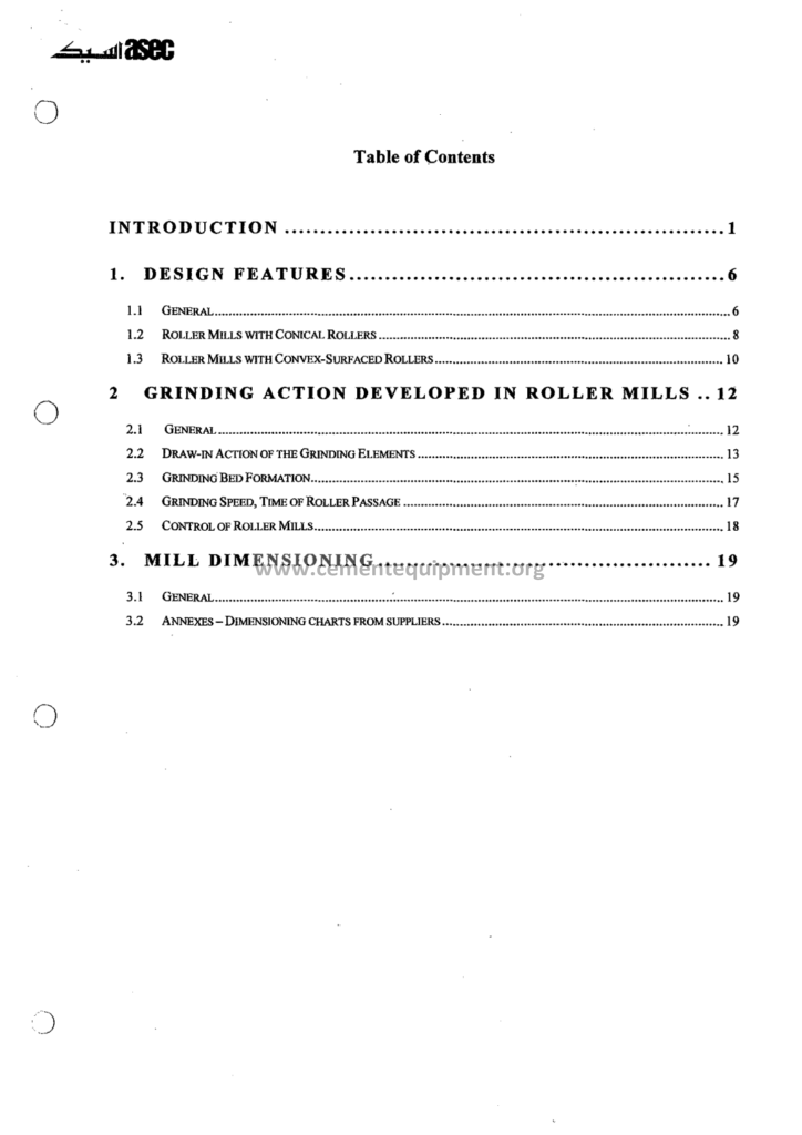
Roller Mills: Complete Technical Guide
The roller mill is the workhorse of the modern cement plant: the vertical roller mill grinds the raw meal at the raw mill station, finishes the cement at the finish mill and dries and grinds the coal at the fuel preparation: the machine that took the place of the planetary ball mill in the new plants: the roller on the table: the bed of the material: the compressed layer: the mill that answers the two demands of the modern industry: the low power consumption and the high drying capacity: the plant engineers work with this machine every day, and the depth of their knowledge decides the difference between the adequate and the excellent performance.
The Complete Cement Technical Package (931 files including the books, the courses, the Excel tools and the presentations: $249.99 one-time: instant download via the PayPal payment) includes this Second Edition roller mill guide with the process diagrams, the operating curves, the troubleshooting tables and the worked examples: the reader of this article follows the file from the grinding principle to the maintenance planning table: the operators, the process engineers and the mechanical engineers of the plant each find their chapter.
The vertical roller mill is not a simple machine: it is a system of the hydraulics, the classifier, the gas circuit and the mill shell working as one: this guide organizes the subject so that the newcomer understands the principle first, the operator masters the variables second, and the engineer moves to optimization and the maintenance third: the article is written to be read with the file in hand: the tables of the file become the working tools of the shift.
1. The Roller Mill Family: From the Loesche Prototype to the Modern Table
The history of the roller mill is the history of the search for the efficient grinding: the first vertical air-swept mill appeared in the mid-1920s in Germany, and the principle remained the same for one hundred years: the material is fed to the center of the rotating table, the rollers press the material against the table in the grinding bed, the ground material leaves the table edge and the gas stream carries the fines to the separator, the rejects return to the table:
- The Loesche type: the grinding rollers with the individual hydraulic cylinders, the conical roller shape, the common architecture of the raw mills;
- The Fuller type: the rollers arranged around the table, the horizontal table with the outer dam ring, the system driven by the central gearbox;
- The Pfeiffer type: the swing-out rollers fixed on the arms outside the mill housing, the advantage of the maintenance access without entering the mill;
- The Polysius type: the roller of the full width hydraulically loaded, the modern machines with the four rollers on the single table;
- The Atox type: the fixed rollers rotating on the axis bearings, the axis of the roller crossing the axis of the table: the classic of the raw grinding;
The market today is dominated by the Loesche, the Pfeiffer, the Polysius and the Atox machines, and their differences are in the details: the number of the rollers, the geometry of the table, the design of the dam ring: the principle remains the bed principle: the energy consumption of the vertical roller mill is 15 to 25 percent lower than the ball mill for the same duty, and the drying capacity is unmatched because the entire mill body is the drying chamber: these two advantages decide the selection of the machine in the new plants.
| Parameter | Vertical roller mill | Ball mill |
|---|---|---|
| Specific power (raw, kWh/t) | 17 – 22 | 22 – 28 |
| Drying capacity | High (up to 20% H2O) | Limited, needs mill inlet pre-dry |
| Grinding media weight | Rollers and table only | 100 – 250 tons of balls |
| Noise level | Low, enclosure possible | High, needs sound insulation |
| Footprint, foundation | Compact, one drive | Large, heavy foundations |
| Maintenance access | Rollers swing out or lift | Balls replenished, liners changed |
The table above is the summary of the selection of the modern plants: the vertical mill wins on the power and the drying, and the ball mill keeps the niche of the very simple plants and the upgrades of the existing stations: the file of this guide walks both families, but the vertical roller mill is the center of the story.
2. The Bed Grinding Principle: The Physics of the Roller on the Table
The vertical roller mill grinds by the compression of the bed of particles between the roller and the table:
- The table: the rotating grinding table, horizontally mounted, driven by the bevel gear of the main gearbox: the material spreads on the table by the centrifugal action;
- The rollers: the grinding bodies, conical or cylindrical, mounted on the shafts with the bearings at the upper end: the rollers do not touch the table: the material bed is always between them;
- The load: the hydraulic cylinders press the rollers into the bed with the force of the order of 40 to 60 kN of the bed area: the pressure of the hydraulic system typically 40 to 90 bars of the accumulator pressure;
- The compression: the particle is broken not by the single impact but by the progressive compression in the layer: the cracks propagate through the layer, an efficiency that the impact mill cannot match: the comminution law of the bed is closer to the Kick than to the Bond models;
- The nipping: the geometry of the roller and the table creates the nip angle that pulls the material into the bed: the slip of the roller on the layer is minimized by the friction, and the mill runs without the metal contact;
The bed thickness is the central variable of the process: the thick bed means the material cushions and the grinding is poor, the thin bed risks the metal-to-metal contact and the vibration: the operators control the bed by the dam ring height, the feed rate and the grinding pressure: the file documents the interplay with the numbers: the pressure on the bed is the force divided by the layer area, and the layer is only 10 to 30 millimeters thick in the raw grinding: the roller literally walks on the carpet of the stone.
3. The Grinding Table and the Rollers: The Geometry of the Contact
The geometry of the grinding elements is the first design chapter of the file:
- The roller shape: the conical rollers of the modern mills give the larger contact area and the better material flow; the spherical and the cylindrical types exist on the older machines;
- The table shape: the flat table with the ring segments or the curved table with the recessed track: the geometry defines the bed profile;
- The wear compensation: the pressure increases as the roller diameter decreases from wear: the stroke of the hydraulic cylinders absorbs the wear of up to 30 to 60 millimeters of the diameter before the re-profiling;
- The materials: the table liners and the roller tires of the high-chromium cast iron with the hardness above 60 HRC, or the composite designs with the tungsten carbide inserts in the high-wear zones;
- The profile: the worn roller develops the flat zones and the grinding efficiency drops; the re-profiling by the grinding restores the original curvature: the plant tracks the diameter and plans the re-profiling every 8,000 to 12,000 operating hours;
The wear measurement is the maintenance instrument of the mill: the contact profile is measured with the templates or the laser instruments during the inspection stops: the average wear rate of the tires of the raw mill is about 1 to 3 millimeters per thousand operating hours, and the database of the file gives the expected rates per material:
| Component | Wear material | Typical life (raw mill) |
|---|---|---|
| Roller tire | High-chromium cast iron | 8,000 – 12,000 h |
| Table liner segments | High-chromium cast iron | 10,000 – 15,000 h |
| Bull ring wear parts | Ni-hard | 6,000 – 10,000 h |
| Nozzle ring segments | Hardfaced steel | 10,000 – 20,000 h |
| Dust extraction duct | Ceramic lined | 10,000 – 20,000 h |
The wear plan of the file is the calendar of the optimized plant: the inspections measure, the planner orders the spare tires in advance, and the mill never stops for the lack of the parts: the wear is not the defeat of the design: it is the scheduled operating cost of the machine.
4. The Gas Circuit: Drying, Conveying and the Separating
The vertical roller mill is air-swept: the gas stream carries the ground material from the table to the separator, dries it on the way, and leaves the mill through the classifier at the top:
- The mill inlet: the hot gas from the kiln, the cooler or the hot air generator enters under the nozzle ring: the typical inlet temperature for the raw mill is 200 to 350 degrees Celsius;
- The nozzle ring: the annular gap around the table, 40 to 90 meters per second velocity range, picks the material off the table and lifts it: the velocities select the size: the coarse material falls back to the mill, the fines are carried up;
- The drying zone: the material surface moisture of up to 15 to 20 percent evaporates while the particles fly with the gas: the mill outlet temperature is controlled at 90 to 110 degrees for the raw, and 75 to 90 degrees for the cement and the coal;
- The mill differential pressure: the measure of the material load in the air circuit: the typical raw mill operating delta-P is 3,000 to 6,500 Pa, and the stable value is the fingerprint of the stable operation;
- The gas flow: 250 to 350 cubic meters per kilogram of the feed in the raw mills, 350 to 500 for the cement: the specific gas volume is the key relationship of the drying capacity;
- The water injection: inside the mill and at the outlet, the water cools the bed and controls the product temperature and the grinding aid effect:
The balance of the gas circuit is the balance of drying and grinding: the too-high temperature dries aggressively but the bed destabilizes and the false air increases; the too-low temperature leaves the material wet, the bed collapses, and the vibration starts: the file teaches the operating window:
- The raw mill window: the outlet gas 90 – 110 °C, the product temperature 80 – 100 °C, the delta-P stable within +/- 200 Pa;
- The cement mill window: the outlet 75 – 90 °C to protect the gypsum dehydration, the water injection at 0.5 – 2 percent of the feed rate;
- The coal mill window: the outlet 70 – 85 °C with the CO monitoring, the oxygen below the limits, the fire prevention rules of the inert gas:
The operators of the file keep the gas window in the shift log: the deviations of the delta-P are the early warning of the ring build-up or the feed change.
5. The Separator of the Mill: The Dynamic Classifier and the Fineness
The classifier of the vertical roller mill defines the product fineness: modern mills use the dynamic separators with the rotating cage:
- The cage rotor: the rotating cage creates the vortex field: the fines pass through the vanes, the coarse particles are thrown back to the cone and return to the table;
- The speed control: the rotor speed, typically 60 to 120 percent of the design, is the main fineness actuator: the higher the speed, the finer the product;
- The air flow control: the gas flow through the classifier sets the cut: the higher the flow, the coarser the cut at the same speed: the two variables together set the Blaine of the cement;
- The bypass: the fine particles carried with the reject stream, the classic weakness of the first generation: the modern delta-wing and the vane designs reduce the bypass below 10 percent;
- The product collection: the fine product leaves the top of the mill into the cyclone or directly to the bag filter, and the filter or the cyclone returns the gas to the mill fan;
The separator speed versus the Blaine relationship is the daily control curve of the plant: the shift increases the speed by 10 rpm and the Blaine rises by 10 to 25 square meters per kilogram, depending on the fineness range: the file contains the curves of the typical mill, and the operators calibrate them with the hourly Blaine samplings: the separator is the last word of the fineness: the roller mill grinds, the classifier decides the quality.
6. The Hydraulic System: The Force That Grinds
The grinding pressure is delivered by the hydraulic system, and the hydraulic circuit is the heart of the machine:
- The pumps: the main pump station delivers the pressure to the cylinders: the pressure 40 to 90 bars typical, adjusted by the process control;
- The cylinders: one cylinder per roller for the individual loading, or the common pressure frame for the balanced load of the four-roller mills;
- The accumulators: the nitrogen-charged piston accumulators absorb the surges of the bed: the sudden hard stone entering the bed compresses the nitrogen instead of the cylinder: the accumulator protects the gearbox and the table;
- The breakaway valve: the hydraulic circuit opens when the pressure exceeds the set limit and the roller lifts over the foreign body: the tramp metal and the large stones pass without the damage;
- The lowering sequence: during the start-up the rollers are held up by the hydraulic pressure and lowered gradually onto the bed: the violent lowering vibrates the mill;
The task of the plant is the optimization of the pressure: the higher pressure means the finer grinding at the same feed, but also the higher wear, the higher power and the risk of the vibration: the operation doctrine: the lowest pressure that delivers the required fineness and the throughput: the file teaches the pressure optimization campaigns with the box-plots of the data: the plant runs at 60 bars for a week, at 70 for a week, and compares the specific power: the result is the operating set point of the year.
| Condition | Typical cause | Immediate action |
|---|---|---|
| Pressure oscillates +/- 10 bar | Bed irregularity, foreign material | Check feed size, reduce pressure 10% |
| Accumulator pressure low | Nitrogen loss, membrane failure | Recharge nitrogen, test accumulator |
| Cylinder stroke at maximum | Tire wear not compensated | Plan re-profiling, increase bed |
| Breakaway valves often operate | Large stones, metal scrap in feed | Inspect screening, check magnetic separator |
The hydraulic condition monitoring belongs to the daily checklist: the pressures of the accumulators are recorded in the log, the leaks are visible immediately, and the oil analysis monthly keeps the pumps young: the health of the hydraulic system is the health of the whole mill.
7. The Feed System and the Reject Circuit
The material enters the mill through the rotary feeder or the double flap valve in the feed chute: the feed is the first variable of the process control:
- The feed size: the vertical roller mill accepts the feed up to 5 percent of the table diameter, typically 40 to 80 millimeters in the raw grinding: the crusher setting decides the mill input;
- The feed moisture: the raw material moisture up to 15 percent and the additives like the wet fly ash require the drying capacity: the feed moisture above the design limit chokes the mill;
- The proportional feeders: the weigh feeders with the variable speed drive deliver the limestone, the clay, the sand and the iron corrective in the correct ratio to the raw mill;
- The foreign material: the tramp metal and the large stones bypass to the reject cone: the magnetic separators and the metal detectors upstream of the mill protect the rollers;
- The reject system: the coarse rejects fall through the nozzle ring into the reject hopper and return via the elevator or the air slide to the table: the reject rate is the powerful diagnostic: the reject rate above 20 percent of the feed signals the grinding problems;
The rejects of the vertical roller mill are the mirror of the process: the normal reject rate in the raw mill is 5 to 15 percent; when the feedstock gets coarser or the mill slows, the rejects climb and the delta-P falls: the operators read the reject weigh as a rolling performance meter: the file documents the typical loops: the feed rate responds to the delta-P, the reject rate responds to the feed size, and the separator responds to the quality.
8. The Start-Up and the Shut-Down: The Sequence Discipline
The roller mill is the thermal and the mechanical system, and the start-up and the stoppage sequences are the protection of the machine:
- The pre-lubrication: the gearbox and the hydraulic system start, the low-pressure and the high-pressure circuits confirm the pressure, and the bearing temperatures are watched;
- The mill warm-up: the hot gas is admitted before the feed at the reduced flow, the mill body pre-heats slowly to avoid the thermal distortion of the housing and the gearbox;
- The feed ramp: the feed starts at 30 to 50 percent and ramps to the full flow over 10 to 20 minutes while the delta-P stabilizes; the rollers lower only when the bed is formed;
- The water and the temperature: the mill outlet temperature reaches the window before the full production; the water injection starts at the stable operation;
- The shut-down: the feed stops first, the mill flushes with the remaining load, the rollers lift, the water stops, and the mill runs for a few minutes empty before the stop: the cooling sequence protects the gearbox from the thermal shock;
The file includes the complete start-up and shut-down checklists with the boxes for each shift: the discipline of the sequence reduces the mechanical failures, the vibration events and the thermal cracks of the housing: the best mill is the one that starts and stops by the book: the rotating equipment lives on the routine.
9. The Process Control of the Mill: The Loops and the Set Points
The automatic control of the vertical roller mill is the collection of the interacting loops:
- The feed loop: the main controller: the feed rate adjusts to hold the mill delta-P at the set point: the feed changes anticipate the delta-P by the 30 to 60 seconds of the process lag;
- The pressure loop: the grinding pressure adjusts in the cascade with the separator speed when the mill power varies: the pressure is reduced when the bed is thin to avoid the vibration;
- The temperature loop: the mill outlet temperature is controlled by the hot gas damper and the water injection valves: the cascades avoid the interactions of the two actuators;
- The separator loop: the rotor speed controls the fineness: the operators trim from the Blaine results every hour;
- The fan loop: the mill fan damper or the variable speed drive holds the gas flow: the fan speed is the drying capacity knob;
- The safety loops: the vibration interlock, the bearing temperature interlocks, the CO monitors on the coal, the low-pressure interlocks of the hydraulics: the protection chain of the machine;
The modern installations add the expert systems on top of the classical loops: the fuzzy logic or the model-based controllers adjust the set points toward the maximum throughput at the minimum specific power: the file explains both the classical cascade philosophy and the advanced layer: the automation begins with the stable loops and the clean instruments: the plant that maintains the calibration wins the control.
The typical operating data of the well-tuned raw mill: the delta-P 4,000 Pa, the feed 150 to 250 tons per hour for the 2,500 to 4,000 kilowatt mill, the specific power 18 to 22 kWh per ton, the separator speed 70 to 90 percent, the reject rate 8 percent: the numbers of the file are the reference of the tuning day.
10. The Optimization of the Mill: The Energy, the Throughput and the Quality
The optimization of the vertical roller mill is the systematic campaign of the process engineer:
- The energy optimization: the specific power of the raw mill at 18 – 22 kWh/t versus the ball mill at 23 – 28 kWh/t is the headline saving; inside the machine, the optimization attacks the pressure, the gas flow and the classifier bypass;
- The throughput optimization: the maximum feed at the stable delta-P: the campaigns raise the feed until the vibration limit or the power limit: the file method: the step tests with the 15-minute stabilization, the logged data, the analysis of the weekly average;
- The quality optimization: the target fineness of the raw meal at 12 to 14 percent residue on 90 microns and 1.5 to 2.5 percent on 212, the cement Blaine 330 to 380 with the right separator curve, the particle size distribution of the roller mill typical steeper than the ball mill:
- The moisture optimization: the feed moisture as low as the process allows: every percent of the moisture costs the drying energy in the gas: the quarry drainage and the stockpile management are the free energy;
- The additive strategy: the grinding aids in the cement mill at 100 to 500 grams per ton reduce the agglomeration and the coating, improve the throughput 5 to 10 percent, and are recovered by the energy saving;
The roller mill product has the different particle size distribution than the ball mill: the PSD of the VRM is narrower, the water demand of the concrete changes, and the cement plants compensate with the blending of the separator streams or the slight fineness increases: the file discusses the water demand, the early strength and the compatibility with the admixtures: the quality is not only the Blaine: the full particle size curve is the product.
11. The Vibration Protection and the Condition Monitoring of the Mill
The vibration of the vertical roller mill is simultaneously the process signal and the mechanical threat, and the plant protects the machine with the layered system:
- The process protection: the vibration sensors on the mill housing and the reducer trip or warn at the set values: the typical warning at 2.5 to 3.5 mm/s and the trip at 4 to 6 mm/s of the root mean square velocity, with the separate high-peak alarm for the individual impacts of the tramp metal;
- The reduction strategy: the integrated control reduces the grinding pressure automatically before the trip: the rapid lowering of the pressure by 20 to 30 percent restabilizes the bed in the seconds, and the feed resumes when the vibration subsides: the automatic loop saves the mill from the hundreds of unnecessary trips;
- The diagnostic analysis: the frequency analysis separates the root causes: the 1x the rotational frequency of the table or the roller, the 2x and the high harmonics of the gearing, the gear mesh frequencies of the bevel and the planetary stages, the roller bearing defect frequencies: the spectrum tells whether the vibration is the process or the mechanical;
- The gearbox surveillance: the main reducer is the most expensive component: the vibration monitoring with the accelerometers on the bearing housings, the oil analysis every 1,000 operating hours for the wear metals, the viscosity, the water and the particle counts: the iron trend of the oil is the wear diary of the gears;
- The thermography: the annual infrared survey of the motor, the gearbox, the hydraulic station and the bearings: the hot spots of the bearings and the electrical connections are found before the failure: the thermal image is the complement of the vibration analysis;
- The lubrication plan: the automatic lubrication of the roller bearings, the grease types per the temperature zone, the relubrication intervals of the file: the roller bearing of the upper end works at the ambient of the mill interior and the grease channel runs through the hollow shaft: the lubrication discipline keeps the roller running the years;
The condition monitoring is the transformation of the maintenance from the calendar to the prediction: the mill that monitors the oil, the vibration and the temperature fits the maintenance to the reality: the file includes the monitoring matrix: the measurement, the point, the frequency and the limit per item: the matrix is the working instrument of the reliability engineer, and the spreadsheet of the package logs the trends automatically and flags the deviations: the predictive maintenance of the roller mill is the planned future of the plant.
The false air measurement belongs to the same discipline: the oxygen measurement at the mill inlet and outlet computes the false air ratio: the leakages of the mill body, the feed chute and the flap valves erode the drying capacity and the fan power: the plant repairs the leaks at the planned stops, and the 2 to 5 percent of the mill power saved is the budget of the reliability department: the report of the file teaches the measurement and the accounting of the false air with the worked example of a 4,000 kilowatt raw mill: the 4 percent false air costs approximately 150 kilowatts of the fan power at the design flow: the numbers of the file make the invisible visible.
12. The Operational Problems: The Vibrations, the Rings and the Build-ups
The operational problems of the roller mill are the daily battle of the operators, and the file maps the symptoms to the causes:
| Symptom | Cause | Remedy |
|---|---|---|
| Vibration above 3 mm/s | Thin bed, feed interruption, foreign body | Raise dam ring, reduce pressure, stabilize feed |
| Delta-P rising steadily | Grinding ring build-up, bowl ring wear | Clean ring build-up, adjust nozzles |
| Reject rate increasing | Coarse feed, worn roller profile | Check crusher setting, check profile |
| Product too coarse | Separator speed lo, vane wear, bypass | Raise speed, check vanes, reduce flow |
| Mill outlet temperature low | Insufficient hot gas, high moisture | Increase gas flow, reduce feed moisture |
| Coating on the table edge | Sticky clay, high moisture, gypsum | Increase pressure, reduce moisture, inspect dam ring |
| False air over 10 percent | Seal wear, worn casing, build-up paths | Pressure test, seal repairs, inspection |
| Motor current at the limit | Overload from the hard bed, kW limit | Reduce feed, reduce pressure, check quality |
The nightly build-up of the raw mill rings is the classical problem: the sticky material agglomerates on the table edge and the pneumatic ring, the delta-P creeps up and the product coarsens: the remedies are the correct pressure, the moisture control and the ring scrapers: the file also covers the grinding ring formation in the cement mills with the hot clinker and the high Blaine: the operators recognize the symptom, apply the remedy, and the shift regains the stability.
13. The Maintenance Planning: The Tires, the Segments and the Drives
The maintenance of the vertical roller mill is planned around the wear components:
- The roller tires: the wear measured at the inspection stops, the re-profiling scheduled at the wear limit, the spare tires pre-ordered: the replacement in 2 to 4 days;
- The table segments: the segment wear tracked by the profile templates, the rotation of the segments extends the life, the change by the segments of one-third at a time;
- The gearbox: the bevel and the planetary stages with the oil analysis every 1,000 hours, the running hours, the vibration analysis quarterly: the gearbox is the longest lead item of the plant;
- The classifier and the fan: the vane wear by the abrasion, the balancing of the rotor, the fan blade hardfacing: the vibration monitoring monthly;
- The seals and the ducting: the false air control: the pressure test of the mill body at the overhaul detects the leak paths: the false air reduction is the energy saving of 2 to 5 percent of the mill power;
The overhaul of the vertical roller mill every 12 to 24 months changes the wearing parts and the seals, inspects the internal structure and the hot gas duct, and verifies the geometry: the file includes the overhaul checklist: the eight-hour inspection plan, the wear tables and the spare part list of the typical 3,000 kW mill: the planner of the plant builds the year with the file: the maintenance is the predictable, and the production is the stable.
14. The Vertical Roller Mill versus the Ball Mill: The Selection of the Finish Grinding
The finish grinding of the cement is the frontier of the debate: the vertical roller mill versus the ball mill:
- The power: the VRM saves 20 to 30 percent of the specific energy in the finish grinding: 25 to 32 kWh/t versus 32 to 40 for the ball mill: the decisive argument of the new plants;
- The quality: the VRM product with the narrow PSD gives the lower water demand but sometimes the lower early strength at the same Blaine: the balance of the different cements;
- The grinding aid: the VRM operates with the increase of the grinding aids because the rotating table flattens the additive effect: the dosage in the VRM up to twice of the ball mill;
- The flexibility: the ball mill tolerates the larger feed sizes and the higher clinker temperatures; the VRM wants the clinker below 65 degrees and the feed below 60 millimeters;
- The maintenance: the ball charge weight of the 4,000 kW mill is 150 tons and its handling is the labor of the overhaul; the VRM maintenance is the roller re-profiling: both machines have the costs, and the file compares the life-cycle numbers;
The plants that operate both machines blend the products for the optimized PSD: the ball mill product fills the coarse tail, the VRM product the middle band: the file presents the blending strategy with the target curves: the selection of the finish mill is the long-term economics: the file gives the engineer the decision tables and the honesty of the trade-offs.
The Frequently Asked Questions
Why does the vertical roller mill vibrate so often?
The vibration is the response of the machine to the bed disturbances: the thin bed, the feed fluctuation, the foreign bodies and the worn profile all express themselves in the vibration: the vibration above 1.5 to 3 mm/s at the reducer is the operator’s warning: the remedy priorities: the feed stability, the bed thickness via the dam ring, and the pressure reduction.
What is the ideal bed thickness and how is it controlled?
The bed of the raw grinding is 10 to 30 millimeters: the operators do not measure it directly but infer from the mill delta-P, the pressure, the vibration and the motor current: the dam ring height is the physical control: the higher ring, the thicker bed: the ring adjustment is the mechanical tuning of the bed.
Can the vertical roller mill grind the wet additives and the slag?
Yes for the limited proportions: the wet fly ash up to 10 to 15 percent of the feed with the drying capacity, the granulated slag up to 40 to 50 percent in the cement grinding with the harder bed and the higher pressure: the slag grinding consumes 30 to 45 kWh/t and stresses the wear parts: the re-profiling intervals shorten, and the plants plan accordingly.
How is the separator fineness corrected when the Blaine is low?
The Blaine is the function of the separator speed and the gas flow: the speed increase by 10 rpm typically raises the Blaine by 10 to 25 m2/kg; if the bypass is high, the vanes are worn and the flow must be reduced: the calibration of the hourly samples against the speed is the working curve of the shift.
The mill delta-P is stable but the fineness drifts: why?
The drift of the quality at the stable delta-P signals the classifier problem: the vane wear, the rotor seal wear or the internal build-up: the plant compares the separator speed against the Blaine trend and inspects the classifier at the next stop: the delta-P is a load meter, not a quality meter.
The file includes the Excel tools for the roller mill?
The Complete Cement Technical Package includes the Excel calculators of the mill power, the gas volumes and the separator speeds, and the maintenance trackers: the engineer inputs the feed, the moisture and the target fineness and receives the operating window in seconds: the tools of the package serve the daily engineering work.
Conclusion
The vertical roller mill is the engine of the modern cement plant: the compression of the bed, the hydraulic force, the air classification and the equilibrium of the gas: the plant that masters the machine masters the energy and the quality at once: the operators watch the delta-P and the vibration, the process engineer tunes the pressure and the separator, and the mechanical engineer plans the tires and the segments: the three disciplines of the file together operate the mill at the design point.
The Complete Cement Technical Package includes this second edition roller mill guide with the tables, the curves, the checklists and the Excel tools: the 931 files, the 249.99 one-time, the instant download: the knowledge of the roller mills in the hands of the shift: the cement plant, the efficient day by day: the package is the library of the cement man: the roller mills, mastered.
Get this Roller Mills file + the full 931-file package
$249.99 — one-time purchase, instant download, lifetime access
This file is part of the Complete Cement Technical Package (931 files) available from cementequipment.org. Respective rights holders; library copy for the licensed single user.