Contents
CLICK HERE TO DOWNLOAD EXCEL SHEETS , BOOKS , MANUALS , OPERATION MANUALS , REFERENCE BOOKS , PROCESS BOOKS
Mill drives
Central drive -Gear and pinion drive
Concerning the efficiency of the ball mill drives, i. e. trunnion connected drive (TCD) versus gear and pinion drive (GP), it can be said that as yet there is no definite evidence indicating the superiority of one kind of drive compared to the other. For comparable mills, both drives can show efficiencies of 98 or 97 %, depending upon the design configurations of both types of drives. However, from a comparision of investment costs for the same mill size, results show that the TCD arrangement is 50- 60 % higher in price than the GP drive. This refers to U.S. price con ditions. According to Schroebler [84], this price differ ence is even much higher. On the other hand, Ackle says that central drives are only 5- 20 % higher in price than gear and pinion drives. Presently it is possible to transmit energies of more than 3000 kW with gear and single pinion drive [84, 85, 86]. Recently, KHD Humboldt Wedag AG constructed a tube mill with gear and double pinion drive with a power input of 6700 kW (about 9000 HP) .
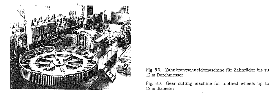
Fig. 8.0. shows a gear cutting machine made by the MAAG-Gear Wheel Co., Zurich, Switzerland. This gear cutting machine is able to cut toothed wheels up to a diameter of 12m, with a max. width of 1.28 m. Dif ferent gear types can be cut, namely spur gear, single helical gearing, left hand as well as right hand, and double helical gearing, left and right on one wheel.
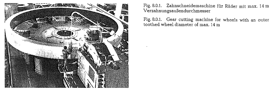
Fig. 8.0.1. shows a protracted version of the 12m MAAG gear cutting machine with an enlarged outer tooth wheel diameter range of up to 14m, which by the end of 1982 was supplied to the David Brown Co. in South Africa [87a]. This is up to now the largest gear cutting machine of the world, and satisfies among others all requirements concerning mill and kiln drives of the cement industry for the next future. Fig. 8.0. and 8.0.1. are from MAAG-Zurich.
Modifications of central mill drives
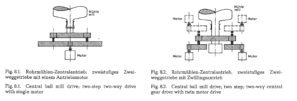
The following four schematic illustrations show var ious modifications of central ball mill drives [87].
Fig. 8.1. shows a two-step, two-way central gear drive, driven by a single motor.
Fig. 8.2. shows a two-step, two-way central gear drive with twin motor drive; if limited by space, the modifi cation indicated by the dotted line can be considered.
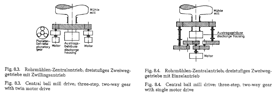
Fig. 8.3. shows a three-step, two-way gear with twin motor drive; first and second steps are planetary gears.
Fig. 8.4. shows a three-step, two-way gear with single motor drive
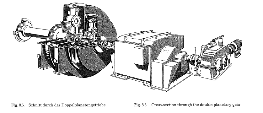
Central drive with two-stage planetary gear (Maag-Zahnriider AG, Switzerland)
This central drive was specially developed for the drive of ball mills.
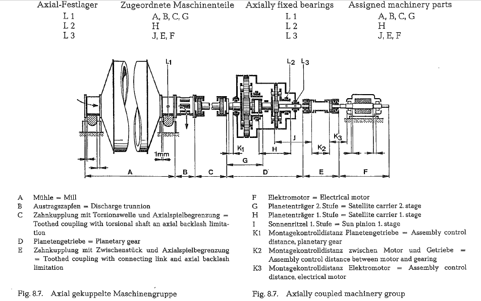
The axially coupled machinery system allows for temperature expansions without housing deforma tion, and without impairing the tooth surface contact (telescopic effect). Position deviations of the mill flange are absorbed by the toothed coupling and by the torsional shaft.
The triple planetary gear system and the sun pionion centered by a three tooth engagement, without any bearing, guarantees a reliable and a smooth torsion transfer.
The complete face contact, resulting from the application of small, plane housing support surfaces, as well as the planetary shafts, which at any time can be positioned by adjustable eccentric rings, and further, appropriately ground toothings, guarantee that the tooth flanks rest upon the total tooth face width. Sleeve bearings or ball bearings can be applied. The advantage of sleeve bearings is an unlimited working life, low risk of tooth damage at bearing defects, as well as the possibility of short term repairs.
The axial slip-on construction avoids the danger of loosening nuts and screws on the rotating satellite carier.
The oil system which serves the lubrication, controls automatically also the optimum gear temperature, depending on the ambient temperature.
With an auxiliary drive which can be switched on to the main drive, inching of the mill can be easily performed.
The reduction ratio of the two-stage planetary gear ing allows the application of a regular, high-efficiency motor with 1000 rpm. The efficiency of an asynchron ous motor increases with rising revolutions, and with increasing capacity. The planetary gear manufactured with casehardened and ground toothings of the sun pinion, and of the planetary wheels, works with a full load efficiency of 98.9 %. According to the manufac turer, this value was proved by precise measurings on a 7500 HP planetary gear. The casehardened and ground toothing, as well as the sleeve bearings, work without wear.

As to the bearing and temperature expansion, three systems are distinguishable (see Fig. 8.7.):
The total space requirement of the drive system is lower than for other design solutions, except for the length, which requires somewhat larger dimensions. The drive arrangement allows for an unrestrained access not only to the mill, but also to the motor. The transportation is mostly performed in two ready assembled gearing units, i. e. the first and the second stage; by these means, assembly work of the particular stages on the construction site, under prevailing dusty conditions, can be avoided.
Cost: The investment cost for a grinding plant with planetary central drive is according to the Maag Co. somewhat higher than that for a mill drive with girth gear and double pinion; on the other hand, the investment cost for a planetary central drive is considerably lower, when compared with gearless mill drive with wraparound motor.
The Maag Gear Wheel Co., Switzerland, determined the investment cost of a 5.5 MW grinding plant consisting of girth gear and pinion drive; according to this, the total plant cost with a planetary central drive was approximately 5 % higher, and with the wrap-around motor drive was approximately 15 % higher than that for a girth and pinion drive. Unquestionably, these values change among other influential factors also with the size and capacity.

For planetary drives, the unit cost per HP is most expedient between 5,000 and 10,000 HP.
With the machinery presently {1982) available to the Maag Co., planetary mill drives up to a transfer capa city of 12 MW, can be manufactured.
The largest planetary gears for ball mill drives in the cement industry supplied at this writing by the Maag Gear Wheel Co., have a transfer capacity of 8 MW.
Since 1967 to 1982, about 70 planetary gears for central drive for the cement industry were manufac tured. With the casehardened and ground toothing, gearing wear was not noticed.
Roller mill drive with planetary gearing and conical gear step (MAAG-Zahnrader AG, Zurich, Switzerland)
As a new drive solution for roller mills, a planetary gear reducer has been developed to replace the pre viously used worm gear reducer. Fig. 8.9.a. shows the basic construction of a MAAG-roller mill drive.
The drive gear consists of the thrust bearing for the grinding table of the mill with the appertaining sup port, the planetary gear, and the separate bevel gear ing. The horizontally arranged electric motor drives via the cyclo-palloid tooth system the sun gear of the planetary gear, which is connected via a tooth clutch coupling to the vertical shaft of the bevel gear. Three tangential driving forces transfer the driving torque via the satellite carrier to the grinding bowl of the mill which is directly connected to the latter. Movable connection elements for the satellite car riers which are susceptible to vibrations, are not necessary.
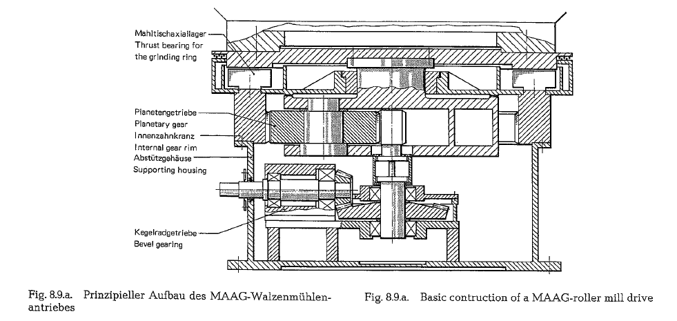
The axial bearing and the internal gear act as bearing reinforcements. The vertical grinding forces are directly supported and transferred to the foundation through the round gear housing having a constant bearing ability on its circumference.
Stop blocks between satellite carrier and housing prevent detrinentaltiltting of the grinding bowl under extreme shock loads. In this way the corresponding danger for the thrust bearing and tooth engagement has been avoided. The three teeth engagements of the free moving sun pinion without bearing, guarantee the proportionate torque distribu tion to the three planetary gears. Correction fac tors for consideration of load deformation, tested at more than 55 MAAG planetary mill drive gears, guarantee – according to the manufacturer – an optimum tooth contact. By using an independent support, the influence exerted by the grinding forces on bevel gear housing, which is sensitive to deformation, and through this inadequate impairment of the flank contact is avoidable. Fig. 8.9.b. shows a MAAG roller mill drive with mill trunnion bearing, planetary gearing, and bevel gear drive.
Shock resistant babbit metal bearings which are reliable in operation, are not only employed for the grind ing bowl. but also for the planetary gear. Unlimited working life, low risk of tooth damage in case of defective bearing, e. g. due to lack of lubricating oil, as well as the possibility of fast repairs are characteristic for this type of bea:ring which stood the test in practice. According to the manufacturer, for the roller bearings which are less exposed to vibrations, a minimum working life of 100,000 hours can be assumed.

Depending on the ambient temperature, the gear temperature is automatically adjusted to an optimum level, through the lubricating oil system. In addition, a high pressure lubricating oil circuit intensifies the lubrication of the thrust bearing at start-up and slow moving speed for extra safety. It is advantageous to locate the lubricating system at a lower level in a separate room.
The planetary gear, having casehardened and correctively ground sun pinion and planetary gear toothing, as well as fully rounded tooth profiles, works with a loss of efficiency of about 0.4 %. At full load the loss of efficiency of bevel gear reducers is between 1.2 and 2.0 %.
Depending on the mill design, an auxiliary drive gear is used for slow rotation. The auxiliary drive gear is connected to the second main motor shaft by an overriding clutch.
The main drive can be easily dismantled into several independent construction groups, which is shown in Fig. 8.9.c. (MAAG).
In addition to the technical advantages, the small space requirement and the low weight, the manufacturing costs are about 20 % lower compared to those of a spur/bevel gear drive of comparable quality.
With machinery and equipment available in 1982, the MAAG Co. is in a position to supply roller mill drives with planetary gearing and conical bevel gearing of up to 4000 kW, at a mill speed of 22 rpm.
By applying simple design changes it is possible to exchange the compound conical bevel gearing by a second planetary gear step, and such double planetary gear box driven by a vertical motor can be supplied for roller mills up to 15,000 kW, at a mill speed of 18 rpm. The full load loss of such a planetary gear is in the range of 0.9- 1 % .


Central drive with the Symetro-gears (F L. Smidth and Co.A/5; Copenhagen)
The F. L. Smidth Company manufactures gears for central drives, called Symetro-gears. For power trans mission up to 8140 kW, a two-way double reduction gear is supplies (see Fig. 8.10.).
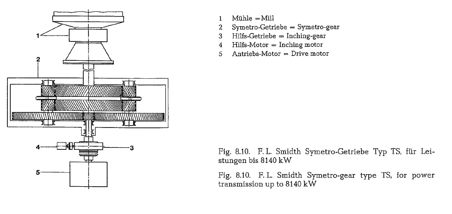
The first stage of the gear has single helical teeth, the second stage is supplied with double helical teeth. The output shaft ,floats'” in a spring-suspended sleeve bearing. The bearing carries the weight of the low speed wheel and part of the shaft. Free-running guide rings on the intermediate shafts keep the gear wheel centered between the shafts; this arrangement ensures an even distribution of the transmission on the two intermediate shafts. By these means, the gear wheel automatically finds the neutral position. Each of the input and intermediate shafts are mounted in two spherical roller bearings.
The first F. L. Smidth Symetro gear was on the market in 1927. Up to 1983, 1750 Symetro gear units have been manufactured.
The efficiency of a Symetro gear was tested by the Technological Institute in Copenhagen. Under full load conditions an efficiency of 99.5- 99.6 % was determined . According to the manufacturer, the high rate of efficiency is due to very low friction. Frictional loss in the tooth system is low, since the second set of gear wheels is supplied with double helical teeth; a special high-grade alloy steel facilitates the application of small moduli for the toothing. The bearing loss is also low, since the double helical too thing eliminates strong axial forces .
Cost comparison: If, according to F. L. Smidth, the price of a single pinion or a double pinion mill drive, including mill and motor is assumed to be 100 %, the price of the same mill with Symetro gear amounts to about 109 %. However, here the longer working life of the central drive, compared to that of the girth gear and pinion drive, should be taken into consideration .
Modifications of girth ring drives
The following illustrations show two types of mill drives employing girth ring and pinion
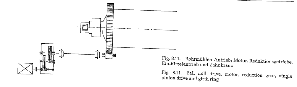
Fig. 8.11.: Gear reducer drive permits the use of standard, high speed, inexpensive motors. Low and high speed reducer shafts are connected by flexible couplings. This arrangement of girth ring and single pinion drive is preferable for larger mills of up to 4000 HP.
At present (1984) Krupp Polysius AG has four ball mills with single pinion drive under construction. Each of these mills has a drive power of 3500 kW (4700 HPJ
Fig. 8.12.: The same drive arrangement as shown in Fig. 8.11., but in twin configuration with girth ring, dual pinion drive and two motors. For currently manufactured mill sizes, this drive arrangement is applicable up to about 9500 HP.

Sizing of mill motors
When sizing a mill motor, a reserve capacity of 15- 20 % depending upon the available type of the motor, should be provided. The mill designer usually asks for 5- 10 % reserve, because variations in the mill charge increase the power requirements. Another 10% is necessary when running the mill without feed; in this case the mill pulls more power. Also, voltage variations can cause an increase in the motor power input.
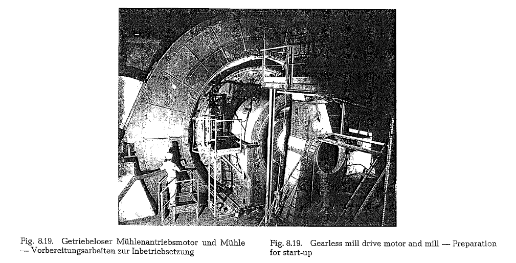
Gearless ball mill drive
The gearless ball mill drive has been established in mill construction since 1969. Large ball mills are directly driven by low frequency electric motors without a speed reducing gear between the motor and the mill and without girth gear and pinion
Electrically it is an application of variable frequency adjustable speed AC drives. The sources of low fre quency for such drives have been frequency conver sion units employing electronic semi-conductors. For the required low 13-15 rpm, a synchronous motor is selected and fed with a current, having a frequency of 5.5Hz.

The gearless ball mill drive can be designed in two basic arrangements. Fig. 8.13. shows an arrangement with the motor rotor supported by a strengthened and extended mill trunnion shaft and bearing. This arrangement retains maximum accessibility to both mill and motor.
Fig. 8.14. shows a wrap-around construction with the motor rotor supported on a specially modified ball mill end bell. This arrangement has the advantage of minimum overall length. Disadvantages are the effects of mill temperature variations, mill deflections under load, and the fact that the ball mill design itself is altered to utilize this arrangement. The cylinder of the rotor is spaced approximately 500 mm from the mill shell; this is not shown on the picture [90].
The gearless drive synchronous motor accelerates the mill from standstill up to operating speed. Within the range of 80- 100 0/o of the nominal speed, the best power factor can be obtained. The mill can for a limited time be operated at very low speeds for positioning the manholes of the mill shell; and no extra equipment is needed.
Costs: As yet only incomplete data are available to make cost comparisons with gear driven mills [90a]. Generally it is said that up to 5000 HP power con sumption, the gearless ball mill drive has substan tially higher initial installed costs than the conven tional geared ball mill drive. This difference tends to become smaller as the mill horsepower increases. If the total cost of a mill with wrap-around motor equals 100 0/o, then the partial cost of the mill together with the lining is 43 0/o, and that of the motor with fre quency converter equals 57 %.
The first finish ball mill driven by a wrap-around motor has been put into operation in 1969 in Le Havre, France. The cement output is rated at 200 MTPH and the motor rating is 8700 HP (metric HP), equal to 6400 kW at 15 RPM. The motor was manufactured by Brown, Boveri and Comp., Baden, Switzerland. The 5 m diameter mill was supplied by the WEDAG Co., now KHD Humboldt Wedag AG Koln, W. Germany.
The tube mill has a diameter of 5000 mm; a bore of 8000 mm was selected for the motor, which resulted in an outer diameter of about 10,000 mm. The active core length is 950 mm. The temperature difference between the rotor rim and the mill drum is in the order of 100 a c. To facilitate transportation and erection, the stator as well as the rotor are built in two sections.
A major advantage of the gearless mill drive is the absence of wearing parts. The extra load on the mill bearings due to the motor weight is only about 15 %, and this does not raise undue problems.
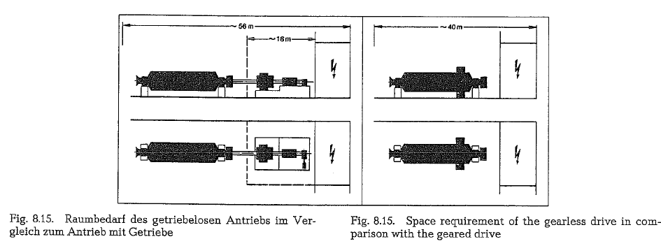
The gearless mill drive allows a more flexible layout of the mill room, since the mill drive is not mechani cally connected to the mill. The space requirement of the gearless drive (Fig. 8.15. right) is about 16m shorter in comparison with the geared drive (left). This results in large space savings. The space saving applies to drive motors up to about 6.5 MW
The cycloconverter supplied by BBC. and shown in Fig. 8.16. is furnished with all control, protection, and measuring equipment for the entire system; this arrangement is designed as a compact converter. The converter is an accessible cabin, fully enclosed with sheet steel, having a floor area of 3.5 x 2.8 m, and constitutes a single transportation unit
The compact converter is located inside the substation, which is marked on the picture by a symbolic electrical arrow.
At present, the size limit for conventional mill drives seems to be around 16,000 HP, 12,000 kW. On the other hand, the gearless drive allows the design of even larger mills since the drive no longer imposes any power limitation and the trend towards larger mill units is continuing.


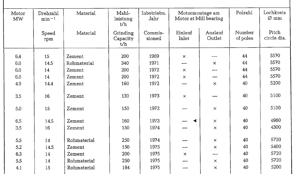
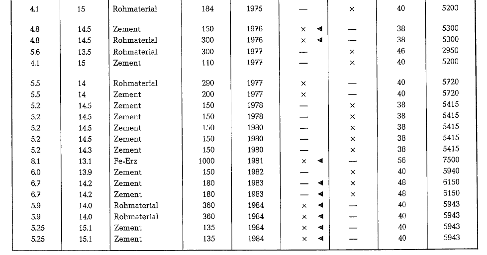
About 36 ball mills with gearless drives are already in operation or ordered at this writing (1984) – the majority with wraparound motor construction (Fig. 8.14.), and the remainder with the motor arranged as shown in Fig. 8.13.

Table 8.3.1. lists the most important data of the ball mills worldwide which are driven by ring motors