Contents
To download the below and all other Useful Books and calculations Excel sheets please click here
To download the below and all other Useful Books and calculations Excel sheets please click here
Clinker Grinding Blueprint written by Grinding Experts
Approximately 85 % of the total energy expended in the production of cement is used for size reduction of the raw material and for grinding; 75% of the total energy is consumed by grinding operation alone. The degree of mill efficiency is controversial, depending on its viewpoint and its manner of definition. According to opposite interpretations, the energy converted into size reduction work lies between 2 and 20 % of the total energy supplied to the mill; the remaining energy is distributed as follows: friction between particles; friction between particles and mill elements; generation of sound, heat and vibration; material turbulence inside the mill; loss of mechanical efficiency from motor to mill.
The theoretically low degree of utilization of the supplied energy is of more interest to the designer of grinding arrangements than to the plant operator, since expenditure of grinding energy can be considered small in comparison to the technological advantage of comminution.
The difference between ball mills and tube mills is the ratio of the tube length to the tube diameter.
Tube mills have a ratio of length to diameter of 3- 6 :1 for ball mills this relation is < 2 : 1.
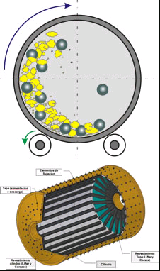
Ball or tube mills are horizontally rotating steel cylin ders where size reduction of the mill feed is per formed by motion of the grinding media. Rotation of the mill cylinder raises the pile of mill feed and grinding media to an optimum height, necessary for grinding operation. Grinding is performed by impact and friction between the grinding balls which hit one against another, as well as between the grinding media and the mill lining itself.
For the efficiency of mills, the following factors are of importance:
- The optimum revolutions, resulting from the mill diameter
- Amount, type, and size of grinding media
- Correct size of grinding compartments
- Grindability of the mill
- The L/D-ratio
- The mill system
- The kind of mill lining
Critical mill speed
The critical speed of a tube mill is that speed of rotation at which the centrifugal power neutralizes the force of gravity which influences the grinding balls;the grinding balls do not fall and therefore do not perform grinding work.
Calculation of the critical mill speed
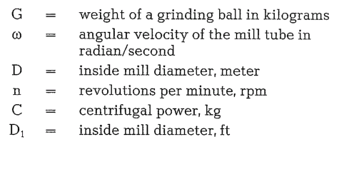
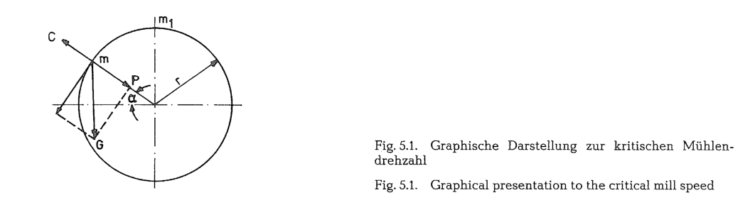
Assumed, a ball is located at the point m of the mill (Fig. 5.1.); the angle a represents the dynamic angle of repose. In this case the ball is subject to the influence of two forces acting in different directions:
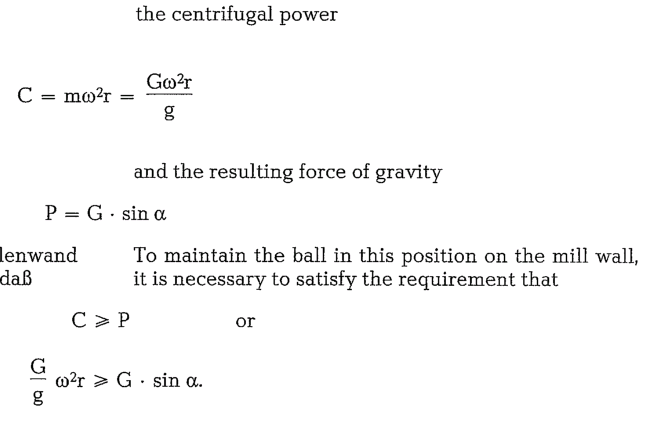
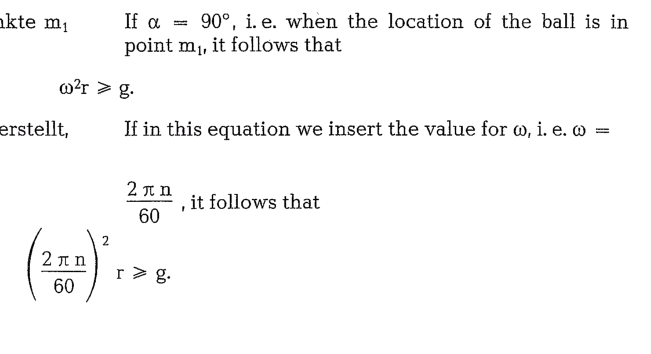
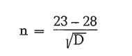
From this the resulting critical speed is
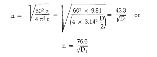
This is the value of critical mill speed at which the grinding balls do not perform any useful work. The pratical mill speed is generally 65-90 0/o of the critical speed. The practical formula is
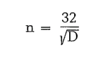
No universal formula exists for the correct mill speedi the following mill speed formulae were devel oped empirically:
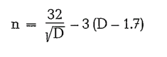
This formula applies for mill diameters > 1.7 meters. Taggarts formula is
and can be applied for mill diameters between 1.8 and 2.2 meters.
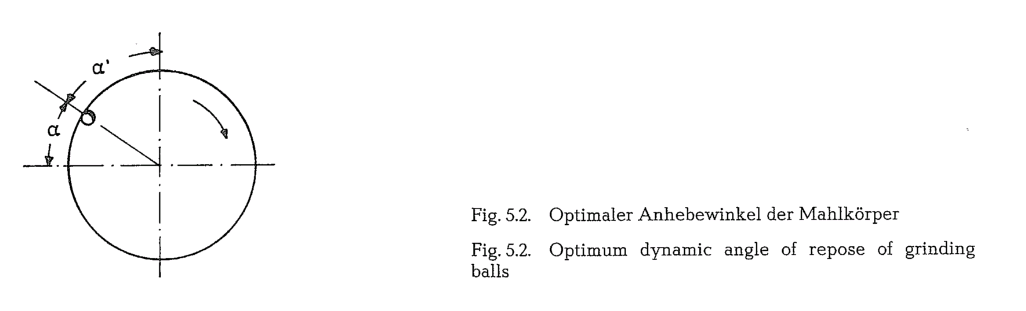
Dynamic angle of repose of grinding balls
Theoretical calculations show that the maximum kinetic energy of the falling balls is at a dynamic angle of repose a equal to 35° 20′ [51]. Sometimes the dynamic angle of repose is the angle which is marked a’ (Fig. 5.2.)i in this case the value for a’ is 54° 40′. This dynamic angle of repose is valid for a mill speed equal to 76 0/o of the critical speed.
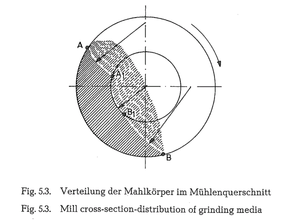
Distribution of grinding media in the mill cross section
Fig. 5.3. shows the distribution of grinding balls in the cross sectional area of the mill during grinding. The field with full shading lines represents the balls which are lifted up by the rotation of the mill drum; the area with dotted lines shows the falling balls, at a dynamic angle of repose a’ = 54° 40′. About 54% of the ball charge is lifted, whereas 46 % of the grinding balls fall.
Number of grinding ball impacts per revolution
Appropriate investigations show that during one mill revolution the grinding balls perform a working cycle varying from 1.79 to 2.85. E. g. a mill with a ball load of 3,401,138 grinding balls performs 3,401,138 x 1.79 = 6,088,037 ball impacts per revolution (mill size is 3.6 x 10.3 m, ball load refers to chapter 5.10.).
Number of ball impacts on mill feed
Joisel developed a formula for determining the num ber of ball impacts on a feed particle in a ball mill. According to this formula, a feed particle being ground requires 30 minutes to pass through a mill 2 m in diameter by 10 m long, and during this time the particle is exposed to 6 ball impacts [52). The reason for this is that the grinding balls in the mill often hit themselves and miss hitting the mill feed particles.
Rebinder says that only every thousandth grinding ball impact in the mill preforms size reduction work; the other ball impacts may be wasted motion [53).
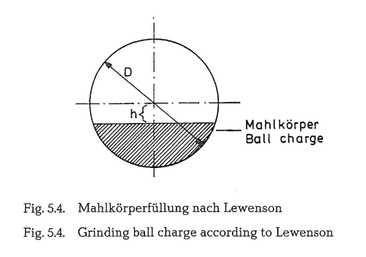
Grinding ball charge in mills
According to Lewenson, the optimum grinding ball charge should be: h = 0.16 D (see Fig. 5.4.).
The degree of mill ball charge expresses the ratio of the bulk volume of the grinding media to the working volume of the mill. The degree of ball charge varies within the limits of 25 and 45 %. A ball charge below 25 % causes sliding of the balls on the mill lining; a ball charge above 45 % causes disturbances along the trajectories of the grinding media.
Degrees of mill ball charge commonly applied are:
for steel balls 28- 45 %
for cylpebs 25- 33 %
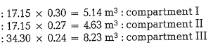
Three-compartment mills can be charged as follows [53a]:
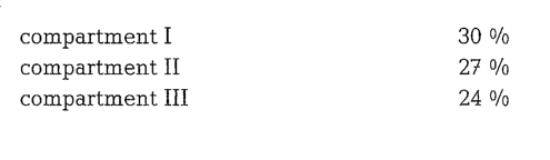
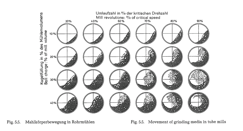
Fig. 5.5. shows the movement of the grinding media in tube mills at various speeds and for various degrees of ball charge. The picture indicates that, generally, at a lower degree of mill ball charge considerable trajec tory movement begins when 60 to 70 % of critical speed is attained; this results in a stronger smashing action of the grinding balls, whereas at higher degrees of filling the grinding media perform more work of friction, which may possibly be a disputed viewpoint [54, 54a].
10.1 by weight [58]. Also Scherer [58a] quotes an example with an S : C ratio of 8.75 (70 t grinding media and 8 t mill feed) In the two-compartment version of the multi-com partment mill which is the most usual design in 1984, the 2nd compartment is charged with < 60 mm balls at filling ratios of 30- 36 %.
Mill charge with grinding media
(Example 5.10.1.}
Calculate the charge of grinding balls of a three-com partment mill for dry-grinding of cement raw mix. The mill feed is a medium hard raw material with a particle size of minus 25 mm. The mill dimensions are:
Inner diameter = 2.5 meters
Length of drum = 14.6 meters; the usefull mill length, minus two partition walls (2 x 0.30 = 0.60 m) is
The lengths of the compartments are:
L1 = 0.25 x 14 = 3.50 m:
L2 = 0.25 x 14 = 3.50 m
L3 = 0.50 x 14 = 7.00 m
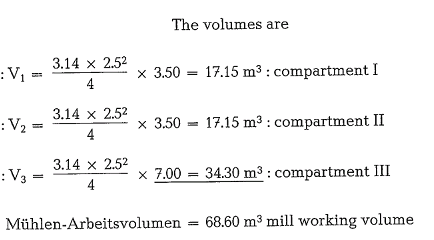
Applying the above mentioned per cents of mill charges, the bulk volumes of the grinding media in the particular compartments are:
The bulk weights are: for grinding balls 4.55 metric tons per m3 and for cylpebs 4.85 metric tons per m3. Thus the weight of the grinding media is:


The distribution of the different ball sizes to the mill compartments could be as follows (see table 5.10.1.).
A given ball size is capable of grinding a wide range of feed sizes without much impairment of the grind ing efficiency. Too great a departure from the opti mum ball size, however, will cause inefficient grind ing. Undersized balls leave in the product small amounts of grossly oversized material. Oversized balls result in lower rates of new surface production [59].
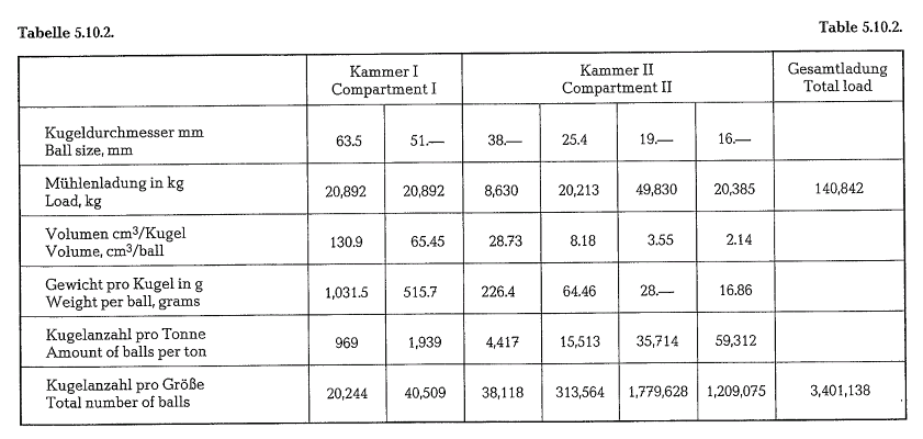
Finish mill charge-sizes of grinding balls
Mill dimensions: 3.65 x 10.3 m, 2-compartment mill, closed circuit grinding with one 5.5 m dia. Raymond separator 1 drive motor: 2500 HPi mill output approx. 49 t/h of Type I cement.
Example 5.10.2(see table 5.10.2.)
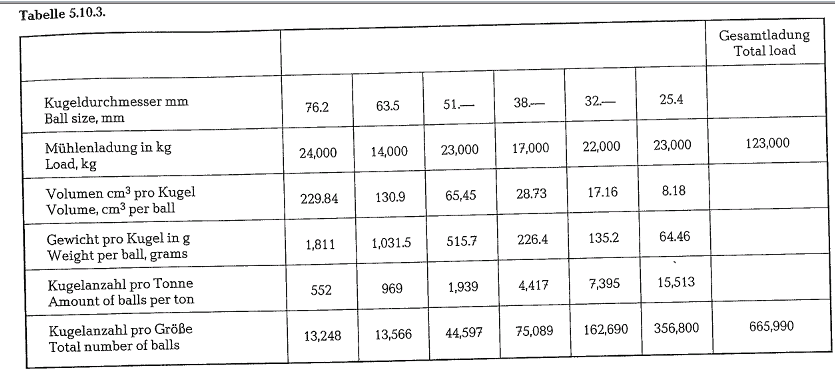
Example 5.10.3.(see table 5.10.3.) Mill dimensions: 3.95 x 6.4 m
One-compartment mill, closed circuit grinding 2 Sturtevant separators 0 4.85 m
2 drive motors a 1000 HP = 2000 HP Mill output: approx. 47 t/h (short tons)
Type I cement
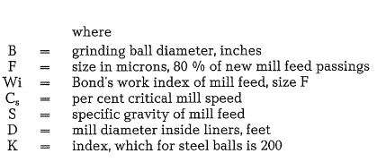
Ball size formula
Calculation of the theoretical ball size according to Bond’s formula [60]
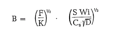
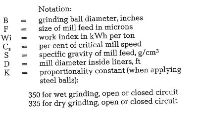
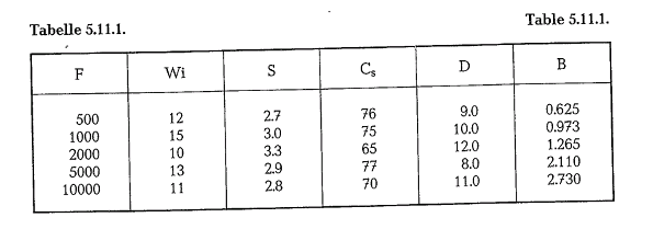
Table 5.11.1. contains ball sizes calculated with Bond’s formula.
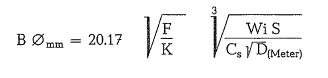
Bond’s ball size formula converted into the metric system [61]:
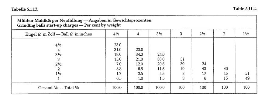
After the ball diameter has been found by calculation, the nearest commercial ball size available should be selected. However, if the calculated ball diameter is 1inch or smaller, somewhat larger balls may be pref erable. A coarser mill feed requires larger grinding balls and vice versa. Based on the maximum calcu lated ball size, Bond suggests the following size distri bution of grinding balls (see table 5.11.2.).
There are other formulas which should be mentioned in conjunction with the size of grinding balls.
-Bond’s empirical formula:
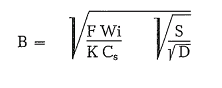
Although this formula is completely empirical, it has been generally successful in selecting the proper size of grinding balls for specific grinding operations.
– Kassatkin’s formula for estimating the minimum size of grinding balls [61a]:
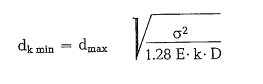
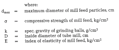
-The Papadakis-formula
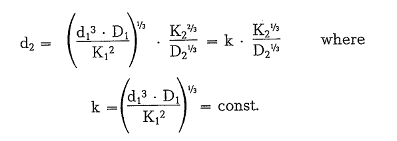
To estimate the diameter of the largest grinding ball, Papadakis[61b] employs a test mill, and converts the test result into that of a regular size mill. He begins from the assumption that the ratio of the kinetic ball energy which is to be determined from the ball weight ( d3) and the drop height ( D), is propor tional to the cross section of the largest mill feed particle ( K2):
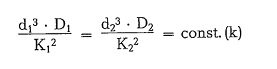
From this, the maximum ball diameter for the regular mill is determined as follows:
Thanks about this information about cement industry and i hope excess
That’s interesting that 85% of energy spent in making cement is used to grind raw material while 75% of the energy spend on just the grinding operation alone. My nephew is in school for engineering and making machines and was telling me about how they make cement. I’ll have to tell him this and see if he knew grinding used so much energy.